- home
- Electronics
>
⬎
LED strips are now used everywhere and sometimes you end up with pieces of such strips or strips with LEDs that have burnt out in places. But there are plenty of whole, working LEDs, and it’s a pity to throw away such good stuff, I want to use them somewhere. There are also various battery cells. In particular, we will look at the elements of a “dead” Ni-Cd (nickel-cadmium) battery. From all this rubbish you can build a good homemade flashlight, most likely better than the factory one.
LED strip, how to check
As a rule, LED strips are designed for a voltage of 12 volts and consist of many independent segments connected in parallel to form a strip. This means that if any element fails, only the corresponding element loses functionality, the remaining segments of the LED strip continue to work.
Actually, you just need to apply a supply voltage of 12 volts to the special contact points that are located on each piece of tape. At the same time, voltage will be supplied to all segments of the tape and it will become clear where the non-working areas are.
Each segment consists of 3 LEDs and a current-limiting resistor connected in series. If we divide 12 volts by 3 (the number of LEDs), we get 4 volts per LED. This supply voltage for one LED is 4 volts. Let me emphasize, since the entire circuit is limited by a resistor, a voltage of 3.5 volts is sufficient for the diode. Knowing this voltage, we can directly test any LED on the strip individually. This can be done by touching the LED terminals with probes connected to a power supply with a voltage of 3.5 volts.
For these purposes, you can use a laboratory, regulated power supply or a mobile phone charger. It is not recommended to connect the charger directly to the LED, because its voltage is about 5 volts and theoretically the LED can burn out from the high current. To prevent this from happening, you need to connect the charger through a 100 Ohm resistor, this will limit the current.
I made myself such a simple device - charging from a mobile phone with crocodiles instead of a plug. Very convenient for turning on cell phones without a battery, recharging batteries instead of a “frog”, and so on. It's also good for checking LEDs.
For an LED, the polarity of the voltage is important; if you confuse the plus with the minus, the diode will not light up. This is not a problem; the polarity of each LED is usually indicated on the tape; if not, then you need to try both ways. The diode will not deteriorate from mixed up pluses or minuses.
A little theory.
LEDs that are used in an LED lamp require 3-4 volts for power. But the power supply produces a much higher voltage. The fact is that in such lamps the LEDs are connected in series and require voltage based on the number of LEDs (and this depends on the power).
Therefore, if the LEDs are connected in parallel, then regardless of their number, the same 3-4 volts will be required for power. Therefore, creating a flashlight should begin by redesigning the board with LEDs.
LED lamp
For a flashlight it is necessary to make a light-emitting unit, a lamp. Actually, you need to dismantle the LEDs from the strip and group them according to your taste and color, according to quantity, brightness and supply voltage.
To remove it from the tape, I used a craft knife, carefully cutting off the LEDs directly with pieces of the conductive wires of the tape. I tried to solder it, but somehow I wasn’t able to do it well. Having picked about 30-40 pieces, I stopped; there was more than enough for a flashlight and other crafts.
LEDs should be connected according to a simple rule: 4 volts per 1 or several parallel diodes. That is, if the assembly will be powered from a source of no more than 5 volts, no matter how many LEDs there are, they must be soldered in parallel. If you plan to power the assembly from 12 volts, you need to group 3 consecutive segments with an equal number of diodes in each. Here is an example of an assembly that I soldered from 24 LEDs, dividing them into 3 consecutive sections of 8 pieces. It is designed for 12 volts.
Each of the three sections of this element is designed for a voltage of about 4 volts. The sections are connected in series, so the entire assembly is powered by 12 volts.
Someone writes that LEDs should not be connected in parallel without an individual limiting resistor. Maybe this is correct, but I don’t focus on such trifles. For a long service life, in my opinion, it is more important to select a current-limiting resistor for the entire element and it should be selected not by measuring the current, but by feeling the operating LEDs for heating. But more on that later.
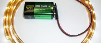
I decided to make a flashlight powered by 3 nickel-cadmium cells from a used screwdriver battery. The voltage of each element is 1.2 volts, therefore 3 elements connected in series give 3.6 volts. We will focus on this tension.
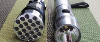
Having connected 3 battery cells to 8 parallel diodes, I measured the current - about 180 milliamps. It was decided to make a light-emitting element from 8 LEDs; it will fit well into the reflector of a halogen spotlight.
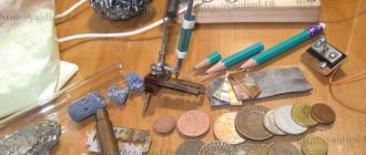
As a base, I took a piece of foil fiberglass about 1cmX1cm, it will fit 8 LEDs in two rows. I cut 2 separating strips in the foil - the middle contact will be “-“, the two extreme ones will be “+”.
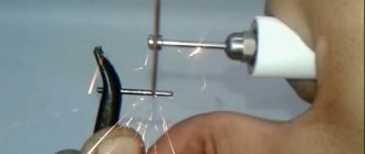
For soldering such small parts, my 15-watt soldering iron is too much, or rather the tip is too large. You can make a tip for soldering SMD components from a piece of 2.5mm electrical wire. To ensure the new tip stays in the large hole in the heater, you can bend the wire in half or add additional pieces of wire into the large hole.
The base is tinned with solder and rosin and the LEDs are soldered in observing polarity. The cathodes (“-”) are soldered to the middle strip, and the anodes (“+”) are soldered to the outer strips. The connecting wires are soldered, the outer strips are connected with a jumper.
You need to check the soldered structure by connecting it to a 3.5-4 volt source or through a resistor to a phone charger. Don't forget about the switching polarity. All that remains is to come up with a reflector for the flashlight; I took a reflector from a halogen lamp. The light element must be securely fixed in the reflector, for example with glue.
Unfortunately, the photo cannot convey the brightness of the glow of the assembled structure, but I will say for myself: the dazzle is not bad at all!
HOW TO MAKE A HELLISH LANTERN FROM AUTOLAMP 2.0, NOW IT WITH A LENS!
I'm assembling a new version of the flashlight from an LED car lamp. LED lamps 2 pcs: https://ali.pub/29tf2e reserve: https://ali.pub/2f6ine Lenses with angel eyes: https://ali.pub/2f6iic without backlight cheaper: https://ali.pub/ 2f6irh Switches 5 pcs: https://ali.pub/2f6i7u reserve: https://ali.pub/2f6iuz Instead of a button, this 22mm switch will do: https://ali.pub/2f6jac Battery 4S 5200mAh: https://goo. gl/2vJjmr Battery 4S 4500mAh: https://fas.st/NAm-pV Battery discharge control buzzer 1-8S: https://ali.pub/2f6o5j Balancing module 3S: https://ali.pub/2d2z4f on 4S : https://ali.pub/2d2z5e
⇒ Files for 3D printing: https://www.thingiverse.com/thing:2853874
My tool: Charging IMAX B6: https://ali.pub/29tn4b 3D printer: https://grbe.st/EU-zCg Soldering station: https://ali.pub/27gxsy reserve: https://ali. pub/27gxwu Step drills up to 32mm: https://ali.pub/29tm3y 12v screwdriver: https://ali.pub/22k4aj Digital caliper 150mm: https://ali.pub/29tmix Large wire cutters: https://ali .pub/29tmyv Small wire cutters: https://ali.pub/29tmmm Knife: https://ali.pub/29tmor
LBP review:
— Digital laboratory module 50V 5A: https://ali.pub/1v9zft — 48V power supply: https://ali.pub/1va19c reserve: https://ali.pub/1va15u — Housing for the module: https:// ali.pub/1va0t7
Hello everyone, a month ago I made a simple and powerful flashlight using an LED car lamp. The flashlight turned out to be compact and as bright as a car headlight, but then I didn’t have a good reflector and had to make one from foil. And I promised you that I will completely redo the lantern when I get normal reflectors.
So, I received reflectors from the C8 flashlight, but they turned out to be nothing, small and not serious. Screw them, so what, I’m going to install car LED lamps - that means I need to use car optics. Fortunately, they sell it on Aliexpress for reasonable money, I ordered lenses for xenon, with angel eyes.
In the flashlight I will use a 30-watt car LED lamp; such lamps have become much cheaper today and cost about 700 rubles per set. Their advantage is that a driver is installed inside, allowing them to be powered from a wide voltage range from 9 to 30 volts, there is a radiator and a fan for cooling. It turns out that you can immediately connect them to the battery and they will start shining, without worrying about current limitation and cooling.
The lenses already have a controlled shutter inside for low and high beam modes. Let's try to use this somehow, the curtain operates from an electromagnet, so it consumes a lot, more than half an ampere from 12 volts.
The main problem with installing lamps in the reflector is that the diameter of the lamps is 14 millimeters, and the hole for installation is only 11. Therefore, using a drilling machine, we drill out the hole. The reflector is entirely made of cast aluminum, so you don't have to worry about it breaking. Now the light bulb can be easily installed in the reflector. The light turned out to be directional and exactly falls into the focus of the reflector if you install a lens.
The angel eyes backlight is implemented via an LED driver, so it can also operate over a wide voltage range. Consumption is about two hundred milliamers.
After this, a long process of searching for a suitable housing began; at first I wanted to use the 110th sewer pipe as on my previous lanterns, then I looked at various plastic pipes for ventilation and drainage in stores - but it was all wrong.
When I came home, I was wondering what else the body could be made from, but I didn’t want to repeat the project again in the 110 pipe - as they say, I was tired of it. In the end, I decided to print the case on a 3D printer. To do this, I take a photo of the lens cap. And I outline it on the computer. The result is a blank with holes for attaching the lens and the outline of the future flashlight. Having put it all into TinkerCAD, we get a blank. Next, it needs to be scaled, the actual size is 87 by 101 millimeters. We set the same dimensions when printing the body.
Next, I print a piece of the body to try on the holes. The printed part fit the lens perfectly. The flashlight has begun to take on its own appearance, and the battery will be located at the bottom.
I am preparing a complete project for printing. It will immediately have ventilation holes on the sides of the case opposite the fan. And at the bottom there is a large compartment for the battery; a transition is made from it into the main compartment so that the wires do not stick out outside. The walls are massive, about 3 millimeters thick. The estimated printing time for such a case is 12 hours, and the plastic consumption is 200 grams, i.e. about 150 rubles. This is a draft print quality with a layer difference of 0.3mm and 100% plastic filling, beauty and perfection are not needed here, speed is important.
If you print with high precision, 0.1mm, then the printing time at 100% filling will be almost two days. And at 20% filling one day. Here you can play with printing speed, filling, choose what is better and faster.
Okay, let's start... during the printing process, due to the large difference between the layers, the case began to crack a little, so every few hours I glued it with acetone.
After 11 hours I received a finished body for the flashlight. It has cracked in some places due to thermal shrinkage of the plastic, but this can be easily fixed by gluing the body with acetone. After processing, I got a glossy body, dark stripes are exactly those places where the layers were poorly laid, acetone got there and glued the layers together. There were no cracks left, the body became solid. For aesthetes, I would like to remind you that this is a high-speed rough print. If you print for finishing, setting the layers to 0.1mm, then it will be the same as with this part.
The battery fit perfectly into place. The wires will immediately go inside the housing. The initial sketch seems like an idiotic child's drawing compared to what we ended up with.
Next, I secured the lamp; it fit neatly into the grooves and was in the focus of the reflector. At a short distance from the wall, it seems that the beam is oblique and irregular, but as soon as you move the lens a little away from the wall, the shadow line begins to straighten. Next you will see how smooth it will look on the ground.
Now all that remains is to put it all together. Lens cap, housing, lens itself with reflector, battery and switches. We screw everything together using the self-tapping screws included with the lens.
The handle I bought at a hardware store turned out to be big. Therefore, I am again preparing a project for 3D printing. I decided to immediately build a button into the handle to switch between low and high beam modes. The button was purchased at a car store for 50 rubles. While the pen was being printed, I embedded two switches into the body of the flashlight. It was necessary to provide a place for them in the case in advance, otherwise I would have to chop up the plastic.
The illumination of the angel eyes turned out to be dual-mode for 100 and 200 milliamps; in principle, you can make a separate mode switch for it too - but this will do.
While printing, I almost ran out of spool, after one hour and 44 minutes the handle was ready, and there were only 5 turns of plastic left, which is less than a meter.
The handle will be located on top. And under the thumb there will be a convenient button for switching the low and high beam modes. We drill a hole in the body for the wires from it. We solder the wires and use heat shrink to install the button in its place in the handle.
I glued the handle itself again with acetone, at first I wanted to strengthen this connection with self-tapping screws or screws, but the plastic stuck together very firmly, so there was no need to strengthen it.
There is a backlight on the switches, but it is designed to operate on 12 volts, so I add a 300 Ohm resistor to reduce the brightness of the backlight when the LEDs operate on higher voltages.
We install the switches in their place. After soldering all the wires together, I actually got a finished flashlight. I connect it to a laboratory technician and check its work. By the way, if you don’t already have a good and compact power supply, I recommend making one like this digital. It is assembled from ready-made modules. In order to get maximum performance from it, you need to power it from a 48-volt 240-watt power supply, then at the output you will get a digital laboratory power supply with currents of up to 5 amperes and the ability to adjust the voltage from 0 to 44 volts. On my channel there is a separate video on assembling this LBP and a link to it will be in the description.
The backlight for the peepholes works, I set the current limit to 2.5 amperes to check the main lamp, and it also turned on, but then it turned out that the lamp does not respond to pressing the near-far button. Well, check out how stupid I am, I soldered the wire to the wrong contact. I re-soldered and glued the button back into the handle. Now it clicks, but the mechanics of the curtain do not work, something is stuck somewhere and does not allow it to move. I disassembled the case, but still didn’t understand what was wrong and what was stopping me. The curtain responds to pressure without any problems.
On low beam, when operating at 16 volts, the flashlight consumes 1.8 amperes, i.e. it turns out almost 30 watts. And at the far end it’s already 2.5 amperes. Thus, my 4-can 5200 milliamp battery will last for 3 hours of low beam operation and a couple of hours of high beam operation. The curtain, of course, can be dismantled and not installed at all, then you will get 1.8 amperes on high beam. And if you use only the backlight of the angel eyes, then the operating time of the flashlight will be about 24 hours.
I soldered the XT-60 connector and am assembling the flashlight. To monitor battery discharge I will use an aircraft model tweeter. It allows cell-by-cell monitoring of any lithium batteries from 1 to 8 cells and will warn if one of the cells drops in voltage below the minimum threshold.
To power the flashlight, you can use any battery with a voltage from 9 to 24 volts. Those. Small three-cell batteries with 1000 milliamps and large ones with 4 banks are also suitable, it doesn’t matter. The power supply is completely universal; the lamp and backlight have drivers for this.
To charge the battery, I will use a specialized charger like IMAX B6. It allows you to balance the banks and select the required charging current. The battery is easily removed from the case and placed on charge, and it can also be quickly replaced with another.
Modifying the flashlight and installing charging inside the housing is not difficult. It is identical to converting cadmium screwdrivers to lithium. You need to use a cheap balancing board for 3 or 4 banks and then charge the battery with a voltage of 12.6 or 16.8 volts, depending on the battery used. But then you will lose the opportunity to replace the battery or use a different voltage. In general, I am completely satisfied with my method, because I can remove and use these powerful batteries not only in a flashlight, but also to work in other devices and aircraft models. Yes, by the way, this battery was bought six months ago at the Hobbyking sale for only 1000 rubles, today there is no discount on it, and it costs 2500. Instead, you can use regular 18650 banks or any other battery. The flashlight itself, excluding the cost of the battery, cost me 1,500 rubles.
I am printing the back cover of the flashlight. After a little modification with a scalpel and adjustment with a file, it fits tightly into place; latches and locks are not needed. The flashlight is ready and it's time to go test it.
As a result, I got a mobile car headlight. The flashlight can work continuously for a long time, the battery is enough for 3 hours of operation of the main light and 24 hours of operation of the angel eyes illumination. And the flashlight works exactly like a headlight. A reflector with a lens distributes light from side to side, limiting its beam from above and below. It turns out to be an oval flattened at the top and bottom precisely for illuminating the surface of the earth into the distance, like car headlights. The curtain provides a clear cut-off line; such a flashlight does not dazzle even if you point it directly at a person.
If you compare the flashlight with the coolest Chinese 50-watt one, it turns out that it overextends it with a central beam. The headlight hits the area on the ground, approximately evenly illuminating the area.
There is no point in comparing it with the mega-popular 7-watt UltraFire. From the word in general! It's nowhere near a powerful LED headlight. Although previously I thought this flashlight was very good and powerful.
I really liked the lantern, it does not dazzle and illuminates exactly what is needed - the surface of the earth into the distance. Previously, I assembled lanterns with 100W LEDs, they simply illuminate the area and are suitable for illuminating massive structures and large surfaces, but they don’t work well on the ground into the distance, but this one shines along the ground into the distance like a headlight.
He's handsome, but he's missing a few things... well, yes, exactly! Logo! What would it be like without him? Now we can consider this project finished.
If you think this flashlight deserves a like, then the install button is located immediately below the video. And of course, don’t forget to subscribe to the channel and turn on notifications when new videos are released. And also write what new projects you would be interested in seeing on my channel. Maybe I can do something on Arduino, and what can I do with the second lens?
Well, as usual, if you want to repeat and make the same lantern, then links to all components and project files for 3D printing are located under the video in the description.
And that’s all for today, thanks for watching, I say goodbye to everyone, bye-bye!
Battery
To power the flashlight, I decided to use battery cells from a “dead” screwdriver battery. I took all 10 elements out of the case. The screwdriver ran on this battery for 5-10 minutes and died, according to my version, the elements of this battery may well be suitable for operating the flashlight. After all, a flashlight requires much lower currents than a screwdriver.
I immediately unhooked three elements from the common connection, they will just produce a voltage of 3.6 volts.
I measured the voltage on each element separately - all of them were about 1.1 V, only one showed 0. Apparently this is a faulty can, it’s in the trash. The rest will still serve. For my LED assembly, three cans will be enough.
After scouring the Internet, I discovered important information about nickel-cadmium batteries: the nominal voltage of each element is 1.2 volts, the bank should be charged to a voltage of 1.4 volts (voltage on the bank without load), discharged should be no lower than 0.9 volts - if several elements are stacked in series, then not lower than 1 volt per element. You can charge with a current of a tenth of the capacity (in my case 1.2A/h = 0.12A), but in fact it can be higher (the screwdriver charges for no more than an hour, which means the charging current is at least 1.2A). For training/recovery, it is useful to discharge the battery to 1 V with some load and charge it again several times. At the same time, estimate the approximate operating time of the flashlight.
So, for three elements connected in series, the parameters are as follows: charging voltage 1.4X3 = 4.2 volts, nominal voltage 1.2X3 = 3.6 volts, charging current - what will the mobile charger with the stabilizer of my manufacture give.
The only unclear point is how to measure the minimum voltage on discharged batteries. Before connecting my lamp, the voltage on the three elements was 3.5 volts, when connected it was 2.8 volts, the voltage quickly restored when disconnected again to 3.5 volts. I decided this: with a load the voltage should not fall below 2.7 volts (0.9 V per element), without a load it is desirable that it be 3 volts (1 V per element). However, it will take a long time to discharge; the longer you discharge, the more stable the voltage will be, and it will stop dropping quickly when the LEDs are lit!
I discharged my already discharged batteries for several hours, sometimes turning off the lamp for a few minutes. The result was 2.71 V with the lamp connected and 3.45 V without load; I did not dare to discharge further. I note that the LEDs continued to shine, albeit dimly.
Charger for nickel-cadmium batteries
Now you need to build a charger for the flashlight. The main requirement is that the output voltage should not exceed 4.2 V.
If you plan to power the charger from any source of more than 6 volts, a simple circuit based on KR142EN12A is relevant; this is a very common microcircuit for regulated, stabilized power. Foreign analogue of LM317. Here is a diagram of the charger on this chip:
But this scheme did not fit into my idea - versatility and maximum convenience for charging. After all, for this device you will need to make a transformer with a rectifier or use a ready-made power supply. I decided to make it possible to charge the batteries from a mobile phone charger and a computer USB port. To implement it, you will need a more complicated circuit:
The field-effect transistor for this circuit can be taken from a faulty motherboard and other computer peripherals; I cut it off an old video card. There are plenty of such transistors on the motherboard near the processor and not only. To be sure of your choice, you need to enter the transistor number into the search and make sure from the datasheets that it is a field effect one with an N-channel.
I used the TL431 microcircuit as a zener diode; it is found in almost every mobile phone charger or other switching power supplies. The pins of this microcircuit must be connected as in the figure:
I assembled the circuit on a piece of PCB and provided a USB socket for connection. In addition to the circuit, I soldered one LED near the socket to indicate charging (that voltage is being supplied to the USB port).
A few explanations about the diagram
Since the charging circuit will always be connected to the battery, the VD2 diode is necessary so that the battery does not discharge through the stabilizer elements. By selecting R4, you need to achieve a voltage of 4.4 V at the specified test point, you need to measure with the battery disconnected, 0.2 volts is the reserve for drawdown. And in general, 4.4 V does not exceed the recommended voltage for three battery cells.
The charger circuit can be significantly simplified, but you will only have to charge from a 5 V source (the computer’s USB port meets this requirement); if the phone charger produces a higher voltage, it cannot be used. According to a simplified scheme, theoretically, batteries can be recharged; in practice, this is how batteries are charged in many factory products.
Working hours
I performed several charges and discharges and got the following results: charging time - 7-8 hours, with the lamp continuously turned on, the battery discharges to 2.7 V in about 5 hours. However, when turned off for a few minutes, the battery regains its charge a little and can work for another half hour, and so on several times. This means that the flashlight will work for a long time if the light is not on all the time, but in practice this is the case. Even if you use it practically without turning it off, it should be enough for a couple of nights.
Of course, a longer operating time without interruption was expected, but do not forget that the batteries were taken from a “dead” screwdriver battery.
Preparing the Lamp
A non-working LED lamp needs to be disassembled. To do this, use a knife or screwdriver to remove the protective cap. Then we remove the board with the LEDs and remove the power supply.
We take a board with LEDs and cut the tracks that connect them. The tracks are clearly visible, they stick out from under the protective film. Now our LEDs are not connected to each other in any way.
All that remains is to connect them correctly. To do this, using two pieces of wires of different colors (for convenience), we connect the LEDs in parallel. That is, “+” to “+”, and “-” to “-“. When connected in parallel, the LEDs will operate independently of each other. And even if one of them burns out, the lamp will continue to shine at the expense of the others.
When all the LEDs are connected, you can check them. To check the functionality, we connect the battery to our board; you can connect it via the power button. The check will show which of the LEDs are intact.
Flashlight housing
The resulting device needs to be placed somewhere, to make some kind of convenient case.
I wanted to place batteries with an LED flashlight in a polypropylene water pipe, but the cans did not fit even into a 32 mm pipe, because the internal diameter of the pipe is much smaller. In the end, I settled on couplings for 32 mm polypropylene. I took 4 couplings and 1 plug and glued them together with glue.
By gluing everything into one structure, we got a very massive lantern, about 4 cm in diameter. If you use any other pipe, you can significantly reduce the size of the lantern.
Having wrapped the whole thing with electrical tape for a better look, we got this lantern:
Installation of main elements.
After checking the functionality of the LEDs, we proceed to install all the elements of the flashlight into the lamp body.
First, we assemble all the elements without the housing according to the diagram. For convenience, I recommend cutting the wires with a margin of 2-3 cm, this makes it easier to mount into the housing.
After assembly, we check the flashlight for functionality. If everything works, install all the elements into the case.
I placed the button at the base of the base. But depending on the configuration, it can be placed in another place, for example on the body of the lamp itself. The battery is placed vertically; its height fits optimally into the case.
I placed the charge controller on the side after making a hole for the socket. And I secured the controller board with a bolt and a textolite washer.
The board with LEDs is installed in its standard place.
Afterword
In conclusion, I would like to say a few words about the resulting review. Not every USB port on a computer can charge this flashlight, it all depends on its load capacity, 0.5 A should be enough. For comparison, cell phones may show charging when connected to some computers, but in reality there is no charging. In other words, if the computer charges the phone, then the flashlight will also charge.
The field-effect transistor circuit can be used to charge 1 or 2 battery cells from USB, you just need to adjust the voltage accordingly.