You can make a homemade diode - a detector for a detector receiver A homemade graphite detector made from a blade, a homemade detector made from sulfur and lead - galena (lead sulfide) PbS, a cuprux diode and many other detector pairs are often described in the old literature of the 20s - 50s of the last century. But for some reason these descriptions always end with the artist’s drawings, and not with photographs of a real homemade detector diode. These same century-old descriptions of detectors with carbon-copy drawings even today drift from site to site. But there are practically no real modern photographs and descriptions of homemade detector diodes. I would like to see this live - a working homemade detector and a description of its settings on a real detector receiver. But now radio amateurs rarely make homemade diodes. It’s understandable - who wants to tinker with amateur retro radio technologies from a hundred years ago. After all, today you can easily find a detector diode in any trash heap. But I still want to “move back” to the beginning of the 20th century and, for the sake of sport, try out different technologies for making homemade detector diodes for a detector receiver.
Advantages of LED lamps
LED lighting in the home is not just modern, but also stylish and bright. Conservative fans of incandescent lamps are left with weak “Ilyich light bulbs” - the Federal Law “On Energy Saving”, adopted in 2009, from January 1, 2011 prohibits the production, import and sale of incandescent lamps with a power of more than 100 W. Advanced users have long switched to compact fluorescent lamps (CFLs). But LEDs outperform all their predecessors:
- the energy consumption of an LED lamp is 10 times less than that of a corresponding incandescent lamp, and almost 35% less than that of a CFL;
- the luminous intensity of the LED lamp is greater by 8 and 36%, respectively;
- achieving full luminous flux power occurs instantly, unlike CFLs, which require about 2 minutes;
- the cost - provided that the lamp is manufactured independently - tends to zero;
- LED lamps are environmentally friendly because they do not contain mercury;
- LED service life is measured in tens of thousands of hours. Therefore, LED lamps are practically eternal.
Dry numbers confirm: LED is the future.
Conventional LEDs
The standard non-blinking LED provides bright, uniform illumination and low power consumption. Along with such qualities as durability, compactness, energy efficiency and a wide range of glow temperatures, this makes it unrivaled among other artificial light sources. A circuit of flickering lamps is assembled on the basis of such LED elements. Let's look at the principle by which they are made.
How to make LEDs blink
An LED flasher can be assembled based on one of the above presented circuits. Accordingly, you will need to purchase the components described above. They are necessary for the functioning of one or another option. In this case, for assembly you will need a soldering iron, solder, flux and other necessary components for soldering.
The assembly of a chain of flashing LEDs is preceded by mandatory tinning of the output contacts of all connected elements. Also, we must not forget about observing polarity rules, especially when connecting capacitors. The finished lamp will flicker with a frequency of about 1.5 Hz or, which is the same, about 15 pulses every 10-second period of time.
Flasher circuits based on them
In order for elementary flashes of light to occur at a certain periodicity, a pair of C945 type transistors or analog elements is required. For the first option, the collector is placed in the center, and for the second, the base is located in the middle. One or a pair of flashing LEDs are manufactured according to the usual design. In this case, the frequency of flashes is set by the presence of capacitors C1 and C2 in the chain.
It is possible to simultaneously introduce several ice crystals into such a system when installing a sufficiently powerful PNP-type transistor. In this case, the LEDs are made to blink when their contacts are connected to multi-colored elements, the sequence of flashes is set by the generator module, and the frequency is set by the specified software settings.
Design of a modern factory LED lamp
The LED here is initially assembled from many crystals. Therefore, in order to assemble such a lamp, you do not need to solder numerous contacts, you only need to connect one pair.
An LED lamp consists of a base, a driver, a heatsink, the LED itself and a diffuser
Types of LEDs
LED is a semiconductor multilayer crystal with an electron-hole junction. By passing direct current through it, we receive light radiation. An LED also differs from a conventional diode in that if it is connected incorrectly, it immediately burns out, since it has a low breakdown voltage (several volts). If an LED burns out, it must be completely replaced; repair is impossible.
There are four main types of LEDs:
- the most common in lighting decorations and displays is DIP (The Direct In-line Package - a crystal with a lens and two conductors);
- bright automobile “Piranha” (similar design, but there are four terminals, which is more reliable in installation and better for heat dissipation);
- Surface mounted diode SMD (Surface Mount Devices - smaller dimensions, better heat dissipation and more application options);
- COB (Chip-on-Board, soldered into the board - the contact oxidizes less and does not overheat, the glow intensity is much higher).
LEDs manufactured using COB technology are a ready-made assembly of several open-frame elements connected into a single light source
A homemade and properly assembled LED lamp will serve for many years, and it can be repaired.
Before you begin self-assembly, you need to choose a power supply method for our future lamp. There are many options: from a battery to a 220-volt AC network - through a transformer or directly.
The easiest way is to assemble a 12-volt LED from a burnt-out halogen. But it will require a fairly massive external power supply. A lamp with a regular base, designed for a voltage of 220 volts, fits any socket in the house.
Therefore, in our guide we will not consider creating a 12-volt LED light source, but will show a couple of options for designing a 220-volt lamp.
Since we do not know the level of your electrical technical training, we cannot guarantee that you will end up with a properly functioning device. In addition, you will be working with life-threatening voltages and if things are not done accurately and incorrectly, damage and loss may occur, for which we will not be held responsible. Therefore, be careful and attentive. And you will succeed.
Drivers for LED lamps
The brightness of LEDs directly depends on the strength of the current passing through them. For stable operation, they need a constant voltage source and a stabilized current that does not exceed the maximum permissible value for them.
Resistors - current limiters - can only be used for low-power LEDs. You can simplify the simple calculation of the number and characteristics of resistors by finding an LED calculator on the Internet, which not only displays data, but also creates a ready-made electrical diagram of the design.
To power the lamp from the mains, you must use a special driver that converts the input alternating voltage into a working voltage for the LEDs. The simplest drivers consist of a minimum number of parts: an input capacitor, several resistors and a diode bridge.
In the simplest driver circuit, the supply voltage is supplied through a limiting capacitor to the rectifier bridge, and then to the lamp
Powerful LEDs are connected through electronic drivers that control and stabilize the current and have a high efficiency (90-95%). They provide stable current even with sudden changes in the supply voltage in the network. Resistors cannot do this.
Let's look at the simplest and most commonly used drivers for LED lamps:
- the linear driver is quite simple and is used for low (up to 100 mA) operating currents or in cases where the source voltage is equal to the voltage drop across the LED;
- The switching buck driver is more complex. It allows powerful LEDs to be powered by a source of much higher voltage than is necessary for their operation. Disadvantages: large size and electromagnetic interference generated by the inductor;
- A switching boost driver is used when the operating voltage of the LED is greater than the voltage received from the power supply. The disadvantages are the same as the previous driver.
An electronic driver is always built into any 220-volt LED lamp to ensure optimal operation.
Most often, several faulty LED lamps are disassembled, the burnt-out LEDs and radio components of the driver are removed, and one new structure is installed from the intact ones.
But you can make an LED lamp from a regular CFL. This is quite an attractive idea. We are sure that many zealous owners keep faulty “energy savers” in their drawers with parts and spare parts. It’s a shame to throw it away, there’s nowhere to use it. Now we will tell you how to create an LED lamp from an energy-saving lamp (E27 base, 220 V) in just a couple of hours.
A faulty CFL always gives us a high-quality base and housing for LEDs. In addition, it is usually the gas-discharge tube that fails, but not the electronic device for “igniting” it. We again put the working electronics into storage: they can be disassembled, and in capable hands these parts will still serve something good.
Types of modern lamp bases
The base is a threaded system for quickly connecting and fixing the light source and socket, supplying power to the source from the mains and ensuring the tightness of the vacuum flask. The marking of the socles is deciphered as follows:
- The first letter of the marking indicates the type of base:
- B - with pin;
- E - with thread (developed back in 1909 by Edison);
- F - with one pin;
- G - with two pins;
- H - for xenon;
- K and R - with cable and recessed contact, respectively;
- P - focusing base (for spotlights and lanterns);
- S - soffit;
- T - telephone;
- W - with contact inputs in the glass of the bulb.
- The second letter U, A or V shows which lamps use the base: energy-saving, automotive or with a conical end.
- The numbers following the letters indicate the diameter of the base in millimeters.
The most common base since Soviet times is considered to be E27 - a threaded base with a diameter of 27 mm for a voltage of 220 V.
Ready flashing LEDs
Flashing LEDs from various manufacturers are essentially functionally complete circuits, ready for use in various fields. In terms of external parameters, they are not much different from standard ice devices. However, their design includes a generator-type circuit and its accompanying elements.
Among the main advantages of ready-made flashing LEDs are:
- Compact, robust housing, all components in one housing.
- Large range of supply voltage.
- Multi-color design, wide variety of shade switching rhythms.
- Economical.
Advice! The simplest flashing LED can be made by connecting an LED crystal, a CR battery and a 160-230 Ohm resistor into one chain, observing the polarity rules.
Usage patterns
The simplest version of the circuit of LED-based flashers produced today, which can be manufactured by radio amateurs on their own, includes:
- Low power transistor.
- Polar type capacitor 16 volts and 470 microfarads.
- Resistor.
- Ice element.
When the charge accumulates, an avalanche-like breakdown occurs with the opening of the transistor module and the glow of the diode. This type of device is often used in Christmas tree garland. The disadvantage of the circuit is the need to use a special power source.
Safety Notes
- Although assembling an LED lamp yourself is not a very complicated process, you should not even start it if you do not have at least basic electrical knowledge. Otherwise, the lamp you assembled may damage the entire electrical network of your home, including expensive electrical appliances, if there is an internal short circuit. The specificity of LED technology is that if some elements of its circuit are connected incorrectly, then an explosion is even possible. So you have to be extremely careful.
- Typically the luminaires are used at 220 VAC. But designs designed for a voltage of 12 V cannot be connected to a regular network under any circumstances, and you must always remember this.
- In the process of making a homemade LED lamp, the components of the lamp often cannot be immediately completely isolated from the 220 V supply network. Therefore, you can be seriously shocked. Even if the structure is connected to the network via a power supply, it is quite possible that it has a simple circuit without a transformer and galvanic isolation. Therefore, you should not touch the structure with your hands until the capacitors are discharged.
- If the lamp does not work, then in most cases poor-quality soldering of parts is to blame. You were inattentive or hurriedly used the soldering iron. But don't despair. Keep trying!
220 volt ice driver circuit
A more reliable way to power LEDs from the network is to use a special converter or driver that reduces the voltage to a safe level. The main purpose of the driver for a 220 volt LED is to limit the current through it within the permissible value (according to the passport). It consists of a voltage driver, a rectifier bridge and a current stabilizer microcircuit.
Driver option without current stabilizer
If you want to assemble a 220 V LED power supply with your own hands, you will need to know the following:
- when using an output stabilizer, the ripple amplitude is significantly reduced;
- in this case, part of the power is lost on the microcircuit itself, which affects the brightness of the emitting devices;
- when using a large-capacity filter electrolyte instead of a proprietary stabilizer, the pulsations are not completely smoothed out, but remain within acceptable limits.
If you make your own driver, the circuit can be simplified by replacing the output microcircuit with an electrolyte.
Probe indicators for searching for phase and zero
A device designed to find zero and phase is called an indicator. Light indicators for determining the phase on neon light bulbs are widely used. Low price, high reliability, long service life. Recently, LED indicators have also appeared. They are more expensive and require additional batteries.
On a neon light bulb
It is a dielectric case, inside of which there is a resistor and a neon light bulb. Touching the electrical wiring wires one by one with the screwdriver end of the indicator, you find the phase by the glow of the neon light bulb. If the light bulb lights up when touched, it means it is a phase wire. If it doesn't light up, it means it's a neutral wire.
Indicator housings come in different shapes and colors, but the filling is the same for all. To prevent an accidental short circuit, I advise you to put a tube made of insulating material on the screwdriver shaft. The indicator should not be used to unscrew or tighten the screws with great force. The indicator body is made of soft plastic, the screwdriver shaft is pressed in shallowly and the body breaks under heavy load.
What is an indicator screwdriver?
This is a tool designed to detect voltage in the electrical network, including hidden ones. Externally, the model may look like a regular flat-head screwdriver with a transparent handle or have a different appearance. However, a probe in the form of a flat bit is required - this is what is used to check the contacts.
Insulation of the handle is also required - the metal part of the device should not come into contact with unprotected human skin, and any metal parts on the handle should not have direct contact with the probe.
They produce products of contact and non-contact types, with different options for sending signals - light, sound, in the form of information on a digital display - as well as with additional functions.
Simple
A working electrical circuit is installed in the case, with a standard set of elements: transistor, resistor, indicator - neon bulbs. The zero phase is the person who closes the contact plate. The tool is not functional - it detects the voltage on the wire, but often does not work when the network voltage is less than 60 Volts. Not suitable for searching for network breaks.
Universal
Portable devices with a wide range of capabilities. An instrument of this type performs contact and non-contact testing, determines open circuits and short circuits using “ringing” of networks, and light and sound warnings help with this. Universal probes are used when repairing or setting up electronic devices and vehicles; they are designed to work with direct and alternating current. The tester operates on a battery, the charge of which is monitored. If the battery loses charge, the universal screwdriver will not work.
The type of indicator screwdriver is selected depending on the intended work. For everyday use, a simple model is sufficient, but for working with electronic devices, choose a universal device.
Method of using an indicator screwdriver
- Non-contact - for a network with voltage up to 600 V. The tip is passed along a wire or electrical appliance that requires testing. If there is voltage, the light will also light up. This is a convenient way to track breaks in the circuit.
- Contact - an indicator screwdriver is used in networks up to 250 V. While holding your finger on the sensor, the tip of the probe is touched to the place that needs to be checked. If there is voltage, the indicator light will light up.
Read more about types of indicator screwdrivers
The closest in design and capabilities are models with a neon lamp and LED. They differ in the sensitivity threshold (for a diode it is significantly lower than 60V) and the presence of additional capabilities.
A screwdriver with a neon lamp has minimal capabilities - it “can” only detect alternating current in a circuit.
This is what the product looks like disassembled. As you can see in the photo, there are no batteries in this device; there is simply nothing to discharge over time. This screwdriver will work, that is, turn on the light bulb, only when in contact with an electrical circuit containing a voltage of at least 60V and the human body.
Important: the current-limiting resistor in the circuit is provided precisely in order to reduce the current in the circuit being tested to a level that is safe for humans.
The model is used to determine the phase and, by elimination, zero.
In more complex products, batteries may be present, in which case the tester can also be used in non-contact mode - the detector will detect the presence of an electromagnetic field, but also only at a certain voltage level.
An indicator screwdriver with an LED works on a similar principle, only a diode acts as an indicator.
Almost always, such products are equipped with batteries and can operate in contact and non-contact mode. Often, in addition to the light indication, there is also a sound indication. This type of tool is considered universal.
Non-contact indicator screwdrivers work on the principle of detecting “interference”, that is, they search for an electromagnetic field. It is easy to distinguish them from contact options - these products have a plastic probe, not a metal one.
Electronic indicator screwdrivers have a digital display as an indicator and, as a rule, an additional phase indicator.
The principle of operation is the same - when the probe touches a section of the electrical circuit, a message about the voltage level appears on the display. This is precisely the main difference between an electronic device and a conventional one, although for accurate measurements it is still better to use a tester or multimeter.
Output voltage stabilization
A stabilizer at the output of the power supply is not always needed. So, if you plan to use a power supply in conjunction with sound-reproducing equipment, then the output must have a stable voltage. And if the load is a heating element, the stabilizer is clearly unnecessary. To power an LED strip, you can do without the most complex power supply module, but on the other hand, a stable voltage ensures independence of the brightness of the glow during changes in the network and extends the life of the LED lamp.
If the decision to install a stabilizer has been made, then the easiest way is to assemble it on a specialized microcircuit LM7812 (KR142EN5A). The connection circuit is simple and does not require adjustment.
Stabilizer for 7812.
The input of such a stabilizer can be supplied with voltage from 15 to 35 volts. A capacitor C1 with a capacity of at least 0.33 μF must be installed at the input, and at least 0.1 μF at the output. The capacitor of the filter unit usually acts as C1 if the length of the connecting wires does not exceed 7 cm. If this length cannot be maintained, then the installation of a separate element will be required.
The 7812 chip has protection against overheating and short circuit. But it does not like reversing the polarity at the input and applying external voltage to the output - its life time in such situations is calculated in seconds.
Important! For load currents above 100 mA, installing an integrated stabilizer on the heat sink is mandatory!
Necessary materials for making an indicator
To make a simple LED device that indicates phase or voltage (approximately), you need to find a working circuit. Then buy or obtain the following parts and tools:
- LED of any type;
- a diode opening with a current of 10-100 mA at a forward potential of 1 V, with a breakdown voltage (reverse) of at least 30-75 V;
- resistor 100-200 kOhm;
- bipolar transistors;
- soldering iron;
- wires;
- metal plate (can be cut from a beer can);
- plastic case, preferably transparent;
- sting, you can take a regular nail.
Chinese soldering iron with USB charging.
DIY diode for detector receiver
In order for the detector receiver to work, detection is necessary. Those. a diode is needed.
An article about how to make it yourself from scrap materials.
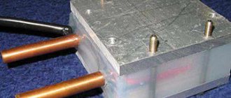
Let's start by getting galena at home, we will need two substances: Lead (Pb) and Sulfur (S)
Galena
- mineral, lead(II) sulfide. Chemical formula of PbS. Synonym: lead shine.
Lead - preferably pure, but if it is difficult to find, lead from a car battery will also work (with worse results, as it contains chemical impurities). After a piece of lead has been found, using a large file we obtain the powder we need from it. Sulfur is also needed in powder form, if it is difficult to find powder, grind a piece of sulfur by hand, the easiest way to do this is in a small porcelain bowl, just crush it. For experiments, a small amount is enough, 2-3 cm in a test tube of each substance is enough.
After the powders are prepared, they need to be mixed in a ratio of 1 gram of sulfur to 5 grams of lead. It is better to make mixtures in small portions (since you may have to carry out more than one melt), using electronic scales with an accuracy of 0.1 grams. If you don’t have scales, do it by eye, about 4 parts lead to 1 part sulfur, here you can experiment a little. Place the resulting mixture in a test tube and lightly compact it, 2-3 cm is enough.
Now, using dry alcohol, gradually warm up the test tube
after the lead begins to melt (this moment can be seen in the photo), we transfer the test tube to a hotter area until the sulfur begins to melt. Almost immediately after the sulfur begins to melt, a reaction occurs in which the mixture becomes red-hot. The process begins at the very bottom, where the melt temperature is highest. As soon as the reaction has begun, the test tube can be removed from the flame and after the reaction stops, wait until the melt cools. After the melt has cooled, carefully split the test tube (if it itself did not split during the reaction