The number of digital gadgets is constantly increasing. A mobile radio, a GPS navigator and a camera were added to the cell phone.
Carrying around a full pot of spare batteries for all this electronic fraternity is difficult, and in the cold season it is also pointless - their capacity and power are greatly reduced at low temperatures.
Therefore, every traveler would like to acquire a device that converts the energy available on a hike into electricity.
Thermal generators turned out to be very practical - sources that require heat to operate. What is the principle of their operation based on and how you can make thermoelectric generators with your own hands - this will be discussed in this article.
What is TEG
This device makes it possible to generate electricity from heat energy.
It should be clarified that the expression “Thermal energy” is not entirely correct, since heat is a method of release and is not a separate type of energy. This definition denotes the general kinetics of structural elements:
- molecules;
- atoms;
- other particles that are part of the substance.
Design features and scope
The basis of the design of a thermoelectric generator is a thermoelement, a heater, a cooler and a load, this can be a lamp, a connector for connecting devices - anything that consumes electricity.
The simplicity of the device, the absence of unnecessary energy conversions and a minimum of moving mechanical components makes the TEG a reliable and durable energy source.
The difference between TEG and TES
At thermal power plants, fuel is used to release steam from a liquid, which rotates the turbine of an electric generator.
With the help of a thermoelectric generator, electricity is generated without intermediary transformations.
Marking
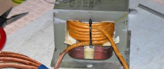
Let's look at how typical module markings are deciphered using the example of Figure 4.
Figure 4. Peltier module marked TEC1-12706
The marking is divided into three meaningful groups:
- Element designation. The first two letters are always unchanged (TE), indicating that this is a thermoelement. The next one indicates the size, there may be the letters “C” (standard) and “S” (small). The last number indicates how many layers (cascades) there are in the element.
- The number of thermocouples in the module shown in the photo is 127.
- The rated current is in Amperes, for us it is 6 A.
The markings of other models of the TEC1 series are read in the same way, for example: 12703, 12705, 12710, etc.
Principle of operation
In the nineteenth century, one scientist discovered the emergence of an electromotive force in a closed circuit, when the temperature in the medium contacts antimony with a conductor.
By heating one of the contacts, a magnetic field arises, which causes an EMF. When the second contact is heated, the EMF flux changes in the opposite way.
By breaking the chain, the opposite potentials are fixed at its edges. This is the basic principle of operation of thermoelectric generators.
- Electricity supply
- Production of explosion-proof equipment
- What you need to know when choosing a wind generator
Twelve 12 years later, another physicist discovered the opposite effect. By passing current through the thermocouple circuit, temperature differences are created in the contacts.
In principle, these two effects are different sides of the same phenomenon, which makes it possible to directly obtain electricity from heat.
Operating principle of modules
At the contact of dissimilar conductors, heat is released or absorbed depending on the direction of the electric current. The flow of electrons has potential and kinetic energy. The current density in the contacting conductors is the same, but the energy flux densities are different.
If the energy flowing into the contact is greater than the energy flowing out of it, this means that electrons are slowed down at the point of transition from one region to another and heat up the crystal lattice (the electric field slows down their movement). When the direction of the current changes, the reverse process of electron acceleration occurs, when energy is taken from the crystal lattice and its cooling occurs (the directions of the electric field and the movement of electrons coincide).
The energy difference of charges at the boundary of semiconductors is the highest and the effect manifests itself most strongly there.
Peltier module
The most common is the thermoelectric module (TEM), which is p- and n-type semiconductors connected to each other through copper conductors.
Diagram of the operating principle of the module
In one element there are 4 transitions between metal and semiconductors. In a closed circuit, the flow of electrons moves from the negative pole of the battery to the positive, sequentially passing through each transition.
Near the first copper-p-type semiconductor transition, heat is released in the semiconductor zone as electrons move to a state with lower energy.
Near the next boundary with the metal in the semiconductor, heat is absorbed due to the “sucking out” of electrons from the p-conductivity zone under the influence of an electric field.
In the third transition, electrons enter the n-type semiconductor, where they have higher energy than in the metal. In this case, energy is absorbed and the semiconductor is cooled near the transition boundary.
The last transition is accompanied by a reverse process of heat release in the n-semiconductor due to the transition of electrons to a zone with lower energy.
Since the heating and cooling transitions are in different planes, the Peltier element will be cooled from above and heated from below.
In practice, each element contains a large number of heating and cooling transitions, which leads to the formation of a noticeable temperature difference, which makes it possible to create a thermoelectric generator.
What does the module structure look like?
The Peltier element contains a large number of semiconductor parallelepipeds of p- and n-types, connected in series with metal jumpers - thermal contacts, the other side in contact with the ceramic plate.
Bismuth telluride and silicon germanide are used as semiconductors.
Advantages and disadvantages of TEM
The advantages of a thermoelectric module (TEM) include:
Disadvantages of modules:
Despite the disadvantages, TEMs are used where high energy costs are not important:
Prospects
At this time, they continue to carry out experiments, selecting the optimal thermocouples to increase the efficiency.
There is a high probability that soon the development of improving the quality of thermal elements will acquire the highest status in the production of material to increase the interaction of thermocouples, using high technologies:
- nanotechnology;
- quantization pits, etc.
It is quite possible to invent a completely different principle, using non-standard materials.
Generator from an asynchronous motor: diagram, table, instructions on how to make it yourself + photo from the master!Do-it-yourself solar battery - step-by-step instructions on how to make and install a solar battery at home (photo and video instructions)
How to choose a solar power plant: ready-made solutions, operating principle, how to choose and install it yourself (photo + video instructions)
There have been attempts to connect microscopic gold conductors with an artificially synthesized molecule. This experience may well lead to success in the future.
Historical reference
Thermoelectric effects, or thermoelectricity, owe their discovery to several scientists. The phenomenon was first discovered by the German physicist Thomas Johann Seebeck in 1821. It is called the “Seebeck Effect”.
The opposite property - heating or cooling of dissimilar conductors by exposure to electric current - was studied by the Frenchman Jean Peltier in 1834, and the effect itself and a thermoelectric converter, called the Peltier element, were named after him. The Russian physicist Emilius Lenz in 1838 and the British William Thompson in 1851 also contributed to the research.
There have been attempts to create TEGs since the mid-19th century. In 1874, the Clamon battery was developed and was powerful enough to be used in printing or galvanizing applications.
The reason why these technologies are not widespread is the low efficiency, when using pure metal pairs - this is hundredths of a percent. Slightly more efficient - 1.5-2.0% - were semiconductor thermoelements, which began to be used in the middle of the 20th century.
You can recall the rather famous “partisan pot” from which radio stations were powered. A model of the thermoelectric generator TGK-3 was produced. Photos of the TGK-3 thermoelectric generator are presented in our gallery.
There was a reference to the topic of thermoelectric generators in Soviet science fiction - in the 1930s, Roman Adamov wrote a science fiction novel “The Secret of Two Oceans”, about the adventures of the submarine “Pioneer”, the energy source of which was a thermocouple.
How to make it yourself
Next, we will briefly tell you how to make a generator with your own hands, which can be used in natural conditions or in de-energized places.
Of course, the power of these devices cannot be compared with a radioisotope specimen, but due to the difficult availability of plutonium and its harmful qualities for the human body, one has to rejoice at this.
A thermoelectric element will be required. It is better to use them not in a single copy, connecting them in parallel, this will increase the power.
However, there is a big problem: it is necessary to select elements with similar parameters, which is quite difficult or expensive; it is easier to purchase a ready-made device.
Solar collectors for home heating: advantages, disadvantages, myths, truth and reviews from owners (130 photos + video)Wind power plants for home - pros, cons and review of the best modern models (105 photos)
- Do-it-yourself biogas plant - step-by-step description of production, 130 photos and video description of the biogas plant
Using one element, the power may not be enough to charge even the simplest gadget.
You will also need a metal case, for example, a used and no longer needed power supply from a personal computer, and a processor cooling element.
Using the Converter
It should be noted that the electric generator of the described type has a relatively high power only until the water placed in the inner mug boils.
And after it boils, its power indicator and, accordingly, voltage drops. In order for this indicator to remain unchanged, a stabilizer should be installed.
This could be the KR1446PN1 microcircuit, which has a DIP package. This microcircuit is connected to a Peltier element, and for it itself you need to specify a five-volt mode, then the voltage will stably remain exactly that way.
The main nuances of the assembly
Initially, you need to apply thermal paste to the base where the main element is intended to be fixed, lean it against it and press it with a cooling part.
The result is a constructive product. Dry alcohol will probably be the best fuel for this device. Next, you need to connect a voltage stabilizing device to the made device.
The diagram can be viewed on websites on the Internet or in other sources offering this topic.
The product is ready, now all that remains is to test it.
Element parameters
This device has several characteristics that affect its performance:
- cold performance. Depends on the maximum permissible current and temperature difference. Measured in watts;
- temperature interval (difference) - the difference between the temperature of the cooled and heated plate. The measurement is made in degrees;
- the maximum amount of current that can be connected for maximum heating/cooling;
- maximum maximum voltage - the value that is the maximum permissible to create the largest temperature difference;
- element resistance. This indicator is measured in ohms and used for calculations of circuits and cascades;
- efficiency factor. In essence, this characteristic represents efficiency. For cheap options it is approximately 0.3, for more expensive ones - up to 0.5.
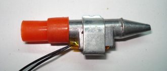
Photo of a thermoelectric generator with your own hands
Did you like the article? Share 
1+
Popular circuits for lm358
There are various devices assembled on the LM358 N that perform specific functions. In this case, these can be all kinds of amplifiers, both UMZCH and in intermediate circuits for measuring various signals, an LM358 thermocouple amplifier, comparing circuits, analog-to-digital converters, etc.
Non-inverting amplifier and voltage reference
These are the most popular types of wiring diagrams used in many devices to perform various functions. In a non-inverting amplifier circuit
the output voltage will be equal to the product of the input voltage by the proportional gain formed by the ratio of two resistances included in the inverting circuit.
The voltage reference circuit is highly popular due to its high practical performance and stability in various modes. The circuit perfectly maintains the required output voltage level. It has been used to build reliable and high-quality power supplies, analog signal converters, and in devices for measuring various physical quantities.
One of the highest quality sine wave generator circuits is the Wien bridge device
With the correct selection of components, the generator produces pulses in a wide range of frequencies with high stability. Also, the LM 358 chip is often used to implement a rectangular pulse generator of various duty cycles and durations
At the same time, the signal is stable and high quality.
Amplifier
The main applications of the LM358 chip are amplifiers and various amplification equipment. This is ensured due to the inclusion features and selection of other components. This circuit is used, for example, to implement a thermocouple amplifier.
Thermocouple amplifier on LM358
Very often in the life of a radio amateur it is necessary to monitor the temperature of some devices. For example, on a soldering iron tip
. You can’t do this with an ordinary thermometer, especially when you need to create an automatic control circuit. For this, you can use the LM 358 op-amp. This microcircuit has a low thermal zero drift, and therefore is classified as high-precision. Therefore, it is actively used by many developers for the manufacture of soldering stations and other devices.
The circuit allows you to measure temperature in a wide range from 0 to 1000 o C with a fairly high accuracy of up to 0.02 o C. The thermocouple is made of a nickel-based alloy: chromal, alumel. The second type of metal has a lighter color and is less susceptible to magnetization; chromal is darker and magnetizes better. Features of the circuit include the presence of a silicon diode, which should be placed as close as possible to the thermocouple. When heated, the chromal-alumel thermoelectric pair becomes an additional source of emf, which can make significant adjustments to the main measurements.
Simple current regulator circuit
The circuit includes a silicon diode
. The transition voltage from it is used as a source of a reference signal, supplied through a limiting resistor to the non-inverting input of the microcircuit. To adjust the stabilization current of the circuit, an additional resistor is used, connected to the negative terminal of the power supply, to the non-inverting input of the MS.
The circuit consists of several components:
- A resistor supporting the op-amp with a negative terminal and a resistance of 0.8 Ohms.
- A resistive voltage divider consisting of 3 resistances with a diode serving as a reference voltage source.
An 82 kOhm resistor is connected to the negative of the source and the positive input of the MS. The reference voltage is formed by a divider consisting of a 2.4 kOhm resistor and a directly connected diode. After which the current is limited by a 380 kOhm resistor. The op-amp drives a bipolar transistor, the emitter of which is connected directly to the inverting input of the MS, forming a negative deep coupling. Resistor R 1 acts as a measuring shunt. The reference voltage is formed using a divider consisting of a diode VD 1 and a resistor R 4.
In the presented circuit, provided that resistor R2 with a resistance of 82 kOhm is used, the stabilization current in the load is 74 mA at an input voltage of 5V. And when the input voltage increases to 15V, the current increases to 81mA. Thus, when the voltage changes by a factor of 3, the current changes by no more than 10%.
Rotary vortex heat generator
In such equipment, the role of the stator is played by a conventional centrifugal pump. The body, hollow inside and cylindrical in shape, can be represented by a piece of pipe with standard double-sided flange plugs. Inside the structure there is a rotor, which is the main structural element.
The entire surface of the rotor is represented by a certain number of drilled blind holes, the dimensions of which depend on the power indicators of the device.
Vortex generator
The gap from the body to the rotating part must be calculated individually, but, as a rule, the dimensions of such space vary within two millimeters.
It is important to note that the performance of a rotary vortex device is approximately 30% higher than that of a static heat generator, but this type of equipment requires monitoring the condition of all elements, and is also quite noisy.
Convector system design
One of the popular ways to heat a private home with electricity is the use of convectors, devices that use air convection in their work.
Design and principle of operation of the convector
Thermostat-controlled heating elements (heating elements) are built into the metal body of the heating device. Each of them is a high-resistance conductor placed in a ceramic shell, hermetically sealed in an aluminum or steel case. This design of the device allows you to increase the area of interaction with air and effectively heat it. The operating temperature of the heating elements varies from 100 to 60C.
Convectors are dependent on the supply of electricity, which makes their owners think about having an alternative heating system in case of an emergency
After turning on the convector, the heating elements begin to heat up. According to physical laws, cooled air sinks down. Here it enters through the lower grille into the structure and passes through the heating elements, gradually heating up and rising upward. There it gradually cools down and falls back down. The process is repeated many times, allowing you to create a comfortable temperature in the room. If necessary, fans can be used to speed up natural convection.
The design features of convectors determine their main disadvantages, including uneven heating of the air. The temperature near the floor itself remains lower than under the ceiling, which, however, is also typical for water heating. Another “minus” is that circulating flows raise dust, which is inevitably present in every home. Today, models are produced that are practically free of this drawback.
Wall or floor option?
Heating can be carried out using different models of convectors. There are two main types of devices:
- Wall structures. They differ in height, which averages 45 cm, and in the method of fastening. They can either be installed directly on the floor or attached to the wall using a special device.
- Floor-standing. Narrow long devices that are usually installed under low windows, stained glass windows and around baseboards. Despite their lower power than wall-mounted convectors, they will need much less time to heat up the room.
Both types of devices are equipped with thermostats, which can be either built-in or remote. Designs are also produced that do not burn oxygen in the room and do not dry out the air.
The wall-mounted convector model is mounted on the wall using special fasteners
Floor-standing models of electric convectors are installed on the floor, and not inside it, like their water counterparts. Therefore, they can be installed at the end of the renovation.
Calculation of the required number of convectors for heating
The number and power of devices needed to heat a country house with electricity are calculated based on the volume of the room in which they will be installed.
First, the average value of the power required to heat 1 cubic meter is selected. Average values for premises:
- with good thermal insulation that meets the energy saving standards of the Scandinavian countries - 20 W per cubic meter. m;
- with insulated floors, walls and double-glazed windows - 30 W per cubic meter. m;
- with insufficient insulation - 40 W per cubic meter. m;
- with poor insulation - 50 W per cubic meter. m.
Based on these values, the power required to heat the room is determined and the required number of heating devices is selected
It is very important to do the calculations correctly. Practice shows that even electric heating of a wooden house is absolutely safe, provided that the equipment is properly selected and installed properly. Convectors are an effective, but far from the only option for heating devices powered by electricity.
A variety of electric home heating systems make it possible to choose the most suitable option, which will ensure efficient and safe home heating
Convectors are an effective, but far from the only option for heating devices powered by electricity. A variety of electric home heating systems make it possible to choose the most suitable option, which will ensure efficient and safe heating of your home.
Problems of traditional electric power industry
Technologies for converting thermal energy into electrical energy, such as thermal power plants, nuclear power plants, CPPs, gas thermal power plants, thermoelectric power plants, thermoelectric generators, MHD generators, have different advantages and disadvantages. The Electric Power Research Institute (EPRI) illustrates the pros and cons of natural energy generation technologies, looking at critical factors such as construction and energy costs, land, water requirements, CO2 emissions, waste, affordability and flexibility.
EPRI's findings highlight that when considering power generation technologies, there is no one-size-fits-all approach to solving all problems, but there are still greater advantages to natural gas, which is affordable for construction, has low energy costs, and produces fewer emissions than coal. However, not all countries have access to abundant and cheap natural gas. In some cases, access to natural gas is threatened due to geopolitical tensions, as has been the case in Eastern Europe and some Western European countries.
Renewable energy technologies such as wind turbines, solar photovoltaic modules produce emissive electricity. However, they tend to require a lot of land and their effectiveness results are variable and dependent on the weather. Coal, the main heat source, is the most problematic. It leads in CO2 emissions, requires a lot of clean water to cool the coolant and occupies a large area for the construction of the station.
New technologies aim to reduce a number of problems associated with power generation technologies. For example, gas turbines combined with battery backup provide contingency reserves without burning fuel, and intermittent renewable resource challenges can be mitigated by creating affordable, large-scale energy storage. Thus, today there is no single perfect method for converting thermal energy into electrical energy that could provide reliable and cost-effective electricity with minimal environmental impact.