This is my first four-legged robot project. The development of the first version lasted about a year, the latest modification is already the fourth. There are two versions - for servos sg90 and mg90. If you are interested in the history of the development of the project, you can look at it on the blog.
Two more projects related to the spider are a simulator in vPython and remote control using Bluetooth. They will be discussed in the second and third parts.
This spider is fun to make, but it will take time and patience to complete.
You can download all the necessary files from this link.
Robot Quadropod
This robot does not have any sensors in its basic configuration. But you can always add them yourself. The main thing is to learn how to program the Quadropod to make beautiful movements and even dance!
To assemble the robot, you will, as always, need body parts, which you can print yourself by downloading them for free from our website. Then you need to buy electronics, the list of which will be shown below. In short, this is an Arduino controller, 8 servos, and that’s basically it.
RobotONRobots
So, let's lay out all the spare parts in front of us. First we need to make the joint. To do this, take a cross-shaped piece and bend it as shown in the figure. This must be done smoothly, using a special form on which we will crimp, and a key. It is worth noting that when printing it is better to use flexible materials, for example, SBS plastic.
RobotONRobots
Then we install servomotors in the claws. First you need to add another fixed shaft to them. You need to unscrew the back cover and put on the plastic part, as shown in the picture. It is better to do this operation with all motors at once. Then insert them into the claws.
RobotONRobots
Now it's time to install the electronics. You can use the board shown in the picture. Install batteries on it. But you can use a regular Arduino Nano with a special shield adapted for servos. In this case, you will need to connect the battery compartment or battery separately. We install all this on the body.
RobotONRobots
Now we install servos on the robot’s body. The shaft heads must match the drawing.
RobotONRobots
We install the joints we made on the servos at an angle of 45 degrees. We secure them in this position with the propellers that come with the engines. We remind you that you must first set all servos to an angle of 90 degrees.
RobotONRobots
We connect the claws in the same way and secure them.
RobotONRobots
The pinout of this board is shown below. If you use Arduino with a shield for the server, then there should be no difficulties with connection. In our case, the board itself provides connectors for these motors - highlighted in blue.
RobotONRobots
Peculiarities:
As with other spider robot models, the most important step is the preliminary adjustment of the servos. In order for the spider’s legs to move freely in any direction, it is necessary to set the position of the servo shaft in advance to the middle position, namely 90 degrees. You can use motors with a metal gearbox (MG version) or with a plastic gearbox (SG). The only difference is durability, especially if you have a child who likes to twirl everything. What do we need from electronics?
- 8 servomotors SG90 or MG90
- Arduino Nano/Uno or TinyPlan V4 Controller Board
- 6 batteries or 12 V battery
Characteristics:
- Easy programming due to single type
- Possibility of using various sensors and sensors
- Great toy for fun and display
- Interesting engineering work
- The need to use a 3D printer
Video:
Necessary parts and components
Before you start assembling the quadcopter with your own hands, you need to acquire all the necessary parts. The brain of our homemade product will be the Arduino Uno flight controller. Its capabilities are more than enough to control a drone.
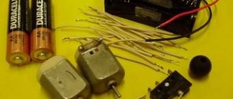
In addition to the microcontroller, we will need:
- Battery (preferably several) 3.7V
- MPU-6050 board (gyroscope and accelerometer installed on it)
- Transistor ULN2003A
- Commutator motors with hollow rotor 0820
- Wires
A few points need to be made. Since we are assembling a cheap homemade drone, our choice fell on commutator motors with a hollow rotor (the so-called coreless motors). They are not nearly as reliable as brushless motors, but they are much cheaper. In addition, you can do without additional speed controllers.
But it is impossible to do without a gyroscope and accelerometer. The gyroscope is necessary to ensure that the quadcopter can maintain a given direction of movement, while the accelerometer is used to measure acceleration. Without these devices, controlling the copter would be much more difficult (if not impossible), since they provide data for the signal that regulates the speed of rotation of the propellers.
We did not include the frame in the list of required parts. You can purchase it, or you can 3D print the frame, beams and mounts for the engines. The second option seems preferable to us, especially since you can easily find quadcopter projects on the Internet.
The frame printed on the printer will be not only light, but also durable. But if you don’t have access to a 3D printer, you can order a frame.
How it all began
I finally received the long-awaited set of mechanical parts for the spider robot.
And in addition to them, I also ordered a lithium-polymer battery, a 30A converter and a microcontroller. In the last series of articles, I showed step by step how I made such a robot from chipboard. The manufacturing accuracy was not very good, there were large gaps, and there was no autonomous power supply. And the whole structure weighed about five kilograms, no less. We will correct all these shortcomings in the new design. So, let's start creating a new monster, it will be called “Spider Robot 2019”.
Video demonstrating the robot in action
I found another video on YouTube (one of the most popular in this topic), which discusses the creation of a robot that avoids obstacles. It is more advanced than the one discussed in this article thanks to the ultrasonic sensor rotating with the help of a servomotor. It also contains the source code of the program (available via the link from the video description), but without explanation. But, I hope, the explanation of the program of the robot discussed in this article will help you understand the program code of this more “advanced” robot.
Hello! If you are interested in what will happen in the end, read the final part.Due to various circumstances, the release of the third part was delayed and yes, we will talk about ESP8266 firmware in the ARDUINO environment. I’ll say right away - I’m not an Arduino guy, this is the fourth time I’ve encountered this environment (three projects from one resource).
Let's start by installing the environment and libraries. The environment can be downloaded from this link. This is a portable version 1.8.5 in a zip archive. We unpack the archive into c:\Program Files\ - that’s it, the environment is installed. Let's move on to installing libraries. To do this, follow the link and do everything that the author writes (I won’t say better how it’s written there, but I don’t see the point in rewriting). Select library version 2.4.2. As a result, we will install libraries for ESP8266 and drivers for CH340G. Now again select the menu item Tools → Board: “Arduino/Genuino Uno”
and select the “Generic ESP8266 Module” board:
Set the settings as in the picture above. Everything is ready, you can flash it.
We open the source code that we downloaded earlier and see that everything is in English and Chinese, respectively, and the control buttons will be in English. This can be seen in the video from the article. Personally, this doesn't suit me. And you? Then open Google Translate and go ahead.
We connect the board to the PC and before applying power to the board, we close GPIO0 to ground, as in the photo:
The LED on the module will blink three times and go out, you can open the output. Click the Download button:
If everything went well, it will look like this:
If you don’t want to bother with Arduino, you can flash it using ESP8266 Flasher. To do this, download the archive at the end of the article and do everything according to the instructions.
For the convenience of connecting the servers, I signed them according to the diagram (top view):
The board was flashed, the servos were connected, all that remained was to connect the boost module and the battery charging module (links to which were given in the second part) along with it. I found an even smaller boosting module in my bins:
By the way, about the connectors where to connect the module:
We solder the connector, then heat-shrink it so that nothing short-circuits and put it in place:
During the “field” tests, it turned out that the battery-powered robot does not work. The reason was an incorrectly routed power supply. It was like this:
You need this:
We take a knife and a soldering iron and fix it:
Where it is black we cut it, where it is red we connect it. This is what happened to me:
Now let's move on to the charge module. We solder the connectors for connecting to the board and the battery, wires to indicate the charge, end of charge and discharge of the battery, and glue double-sided tape:
At the same time, we are modifying the battery:
We connect the charge board, glue it and solder the remaining wires:
That's it, now you can screw the bottom cover into place:
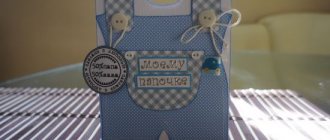
In the first part I said that there will be two toys. So here it is. We take the robot's eyes from version 2.0, color them and glue them to the top cover:
We connect the battery to the connector, place it in the cover (or glue it to it with double-sided tape if the battery is smaller than what I used) and screw it on:
That's it, now you can try to “revive” our spider. Looking ahead, I will say that it is better to start doing this by charging from a phone/tablet or an external battery (Power Bank) with an output current of 2A. We connect the “cord” to the board, supply power from USB, go to the Wi-Fi settings on the phone/tablet and see our network:
To connect to the GOSHA 1.0 - 5F57 network, where 5F57 is the MAC address of a specific module, you need to enter the password 12345678 . If you want to change it, in the source code, look for the line const char WiFiAPPSK[] and change it.
Open the browser on your phone/tablet and enter 192.168.4.1 in the address field and press enter. The page will load:
In general, if you add one of the lines /setting, /zero, /editor to the address, the following pages will load:
What are the remaining pages for? To set the servo positions. So.
/setting – this is the setting of the zero state of the servos,
/zero – this checks the zero state of the servos,
/editor is the motion editor.
As they say: “It’s better to see once...” Video on setting the zero position of servos from the author of the robot:
And finally, a video of what happened in the end:
That's all! Good luck with the assembly everyone! If you have any questions, write.
PS Due to the identified shortcomings, the board was slightly redesigned:
PPS It was decided to move the charge controller to the board:
This circuit was taken as the basis for the charge controller:
The discharge indicator is assembled according to the following scheme:
All versions of the boards can be downloaded at the end.
PPPS During operation, some aspects of the operation of the charge controller (more precisely, the discharge/overcharge protection unit) were found, namely, protection during a sharp load jump (all servos consume 1.6A at the peak). To avoid this, before applying power, I manually transfer the spider’s legs to the zero state (you can see it in the video), and start control with the “Wait” or “2nd dance” button.
PPPPS I ordered boards for Power Bank with 5V/2A output in China. After arrival and verification there will be an addition to the article.
First part.
Second part.
First experience in assembling a walking robot. Quadruped Robot
Plans for this project have been spinning in my head for a long time and were as follows:
1. Find a ready-made project of a walking robot running on an Arduino board.
2. The robot must be controlled from a phone.
3. Look at the connection points of the parts and study the mechanics of the robot.
4. Handle and study electronic components.
I think that having no experience with such things, the plan was carried out 100%.
Starting from the search for a ready-made robot project, we had to immediately study the electronic component, since almost all projects were implemented by foreign users and they use the opportunities of their location without resorting to purchasing components from our “Chinese friends.”
After the robot was found and the components were ordered, it was time to print the parts. This is where the biggest surprise awaited us: the parts of this robot turned out to be terribly designed and required a large number of supports when printing, and they also had to be placed on the table in a rather peculiar way. You place it with a minimum number of supports - the geometry moves out due to the fact that the part is at an angle, if you place the part in a normal way - a large number of supports appear and in the future the possibility of breaking the part in the process of removing the supports, which happened 3 times, so the printing option was chosen with a minimum amount of support.
The process of assembling a frame with servos also brought quite a lot of useful knowledge, especially about how not to design products. The seats for the servos were modeled directly mm to mm. To begin with, a needle file came to the rescue, and then more stringent measures were taken - side cutters were used and some parts are now “slightly” different from the original.
The time has come for the electronic component and firmware of the boards. Oddly enough, there were no problems at all with the electronics, but I had to tinker with the Arduino firmware and Wi-Fi module for a couple of days and study quite a lot of information.
Aaaand here is the culminating moment of launching the robot, the servos began to move, the lights sparkled, everything was connected to the phone, but the robot refused to walk at all, in my opinion, the stupidest design mistake was discovered. The paws turned out to have a small contact patch with the floor and the position of the paws at a slight angle to the plane led to the fact that the paws simply spread out in different directions when walking. This problem has never been completely resolved. To begin with, I tried using electrical tape (I wanted to try heat shrink, but I didn’t have the right size at hand), stretch film, hot glue, but the final version was sandpaper.
In addition to all this, there seems to be a problem in the code. The last movement that the hind leg makes before lifting up is to row under itself, thereby pulling the entire robot back, instead of pushing it forward. I reconnected the paws to other pins on the board, but this did not help.
As a result, 4 weeks passed from the search for the project to its complete completion and good experience was gained.
The printing took 30 hours and 227 grams of PetG were used.
From electronics, the following components were needed:
Servo drive SG90 - 12 pcs.
Arduino Nano - 1 pc.
Wi-Fi module WeMos D1 mini on ESP-12F ESP8266 chip — 1 pc.
PCA9685 - 16-channel PWM/Servo module with I2C interface - 1 pc.
Switching Buck Regulator 5V/6V 3A UBEC for 2-6S LiPo - 1 pc.
Mini 360 DC-DC Buck Adjustable Power Converter - 1 pc.
Dupont jumpers female-female 100 mm - 8 pcs.
JST connector 2 pin female with wires - 1 pc.
Self-locking push-button switch DS-228 — 1 pc.
Battery 11.1V 550mAh LiPo 3S — 1 pc.
Of necessity:
Universal charger Skyrc IMAX B6 mini 60 W
Although there were quite a lot of difficulties with the project and it does not work as I would like, I consider it very valuable from the point of view of experience. Now there is a great desire to independently model your own four-legged robot.
Link to original project:
Quadruped Robot
Link to my Instagram:
Hexagon Sector 3D
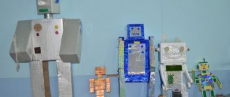
And here is the actual photo in assembled condition
Details
To assemble the robot, I purchased the following parts from Ali Express:
- set of mechanical parts for legs and body;
- microcontroller STM32F407VET6;
- MG995 servo drives (20 pcs);
- Bluetooth module NS-05;
- converter 30A, 5V;
- battery 11.8V.
The mechanical part is assembled without any questions. But how to place everything else? There is room for creative thought to run wild here. The holes on the case almost coincided with the holes on the microcontroller board. Therefore, the location of its installation was immediately clearly determined. We will also hide the battery inside the case. As a result, there is practically no space left inside.
I chose 11.1V battery output voltage. At first I wanted 7.4V, since the controller has a stabilizer, and servos can withstand voltages up to 7V, plus a drop on the supply wires. But then I decided not to risk it, because the cost of servos is half the price of all the entire parts. Therefore, I decided to do everything right, I selected a 12V to 5V converter with a maximum current of 30A. This is enough to power 18 servos even when working at full stop. So the battery turned out to be 11.8V.
The power source will be placed on top. To connect the servos, I made two adapter boards that fit seamlessly into the existing design. I think it turned out compact and beautiful.
The set of mechanical parts included bearings (6 pieces) for installing the shoulder joints on the body. Without them, there will be increased friction and excessive load on the servo shaft.