Electronics lovers and people interested in robotics do not miss the opportunity to independently design a simple or complex robot, enjoy the assembly process itself and the result.
There is not always time or desire to clean the house, but modern technology makes it possible to create cleaning robots. These include a robotic vacuum cleaner that travels around rooms for hours and collects dust.
Where to start if you want to create a robot with your own hands? Of course, the first robots should be easy to create. The robot that will be discussed in today’s article will not take much time and does not require special skills.
Continuing the theme of creating robots with your own hands, I suggest trying to make a dancing robot from improvised materials. To create a robot with your own hands, you will need simple materials that can probably be found in almost every home.
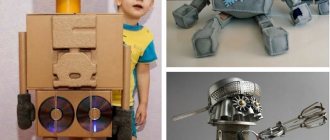
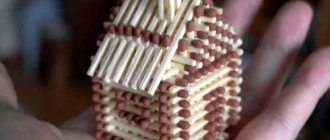
The variety of robots is not limited to the specific patterns by which these robots are created. People constantly come up with original, interesting ideas on how to make a robot. Some create static sculptures of robots, others create dynamic sculptures of robots, which is what we will discuss in today's article.
Anyone can make a robot with their own hands, even a child. The robot, which will be described below, is easy to create and does not require much time. I’ll try to describe the stages of creating a robot with my own hands.
Sometimes ideas for creating a robot come completely unexpectedly. If you think about how to make a robot move using improvised means, the thought of batteries comes to mind. But what if everything is much simpler and more accessible? Let's try to make a robot with our own hands using a mobile phone as the main part. To create a vibration robot with your own hands, you will need the following materials.
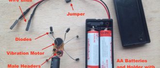
to assemble the bug you will need: - 2 small 1.5 volt motors (you can buy or remove them from old toys (see photo).) - 2 small paper clips - 2 large paper clips
2 AAA or AA batteries
1 AAA or AA battery holder (can be purchased or removed from some toys)
1 2 cm insulation
1 wooden ball (used as a wheel) (you can use any other stabilizer, for example, removing the wheel from some old or unnecessary toy) - 1 meter of electricity. wires - 2 small SPDT switches (you can buy or remove, for example, from an old computer mouse)
as well as tools: * soldering iron + some tin * glue gun and a glue stick for it (the glue stick can be melted simply with a soldering iron, but it is recommended to do this with a glue gun) * wire cutters (to remove the insulation)
and here are all the details
Assembly:
1. electric mode wire into 13 pieces of 6 cm each and remove the insulation from them (on both sides) 1 cm each.
2. Solder the wires to each of the components (except batteries), see the figure.
solder the wire to the batt. holder (blue)(third connection)
3. Turn the battery holder over and glue the switches to it in a “V” shape (see photo)
4. Glue 2 motors between the switches so that the chassis of the motor itself touches the ground
5. From a large paper clip and a ball we make a stabilizer (a wheel to make it easier to move along the surface)
6. connection
this is how it should all look
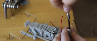
7. take 2 small ones. paper clips and make whiskers for a beetle out of them
8. carefully glue the mustache to the switches (use a little glue for this so as not to glue the switch itself)
9. wrap a little insulation on the running gear of the motor (for better grip)
10. Insert batteries
and you're done!)
It's not very difficult. I just did it myself!!!
The funny thing is that when he touches an obstacle with his right tendril, the other wheel stops and he turns to the left, and vice versa. (Goes around obstacles)
Walkers made from paper clips and a motor are not just homemade toys, but also a whole arsenal of technological techniques and engineering thinking.
Making such a robot with your own hands is not only interesting, but also develops fine motor skills of the fingers, and for a child it will be a revelation - after all, a real walking robot is created out of nothing!
To assemble a simple working robot from ordinary paper clips with your own hands, you will need several simple and easily accessible materials. Firstly, these are the metal clamps themselves, as well as a small set of tools. The tools you will need are a soldering iron, solder, pliers, wire cutters, round nose pliers, as well as a small electric motor with a gearbox and a battery for it.
First, you need to make a support frame from a long and thick paper clip, that is, bend it into a rectangle and securely solder its ends with solder. Parts and elements of the robot will be installed on this frame during the assembly process.
Next, you need to make loops on which the robot’s legs will be attached. They will need to be soldered to the rectangular frame using a soldering iron. Then the small legs of the walking robot are made from paper clips. In this case, it is advisable to first assemble the complex front legs, and then all the rest.
After assembling the robot's limbs, you need to start making the crankshaft. The clamp for it must be strong and absolutely even.
The crankshaft should be carefully prepared using pliers and round nose pliers. When the shaft is finished, it should be carefully placed on the motor gear. After this, special connecting rods are made that will connect the robot's legs to the crankshaft. The gear is then soldered to the crankshaft.
Then a battery and a switch are installed on the robot frame. If everything is done correctly, the robot will begin to walk.
Here is a video instruction on how to make a homemade walking robot from paper clips with your own hands, watch it if you don’t understand something from the article.
Part II. Joints and ligaments.
Tell students that joints allow our limbs to bend and ligaments hold the bones of our skeleton together. How will the mobility of parts in a robot be ensured, the parts of which must freely change their position relative to each other?
Have teams find the following pins in their robotics kit boxes.
Ask students how the pins in each pair are different?
Ask students in teams to connect two beams with each pin and test the rotation of the beams relative to each other. Beams connected by which pins rotate more freely? Make a conclusion about which pins are most suitable for movable joints. Ask the question, what other elements from the construction set can students suggest using in places of movable joints in addition to pins?
Part III. Prototyping a robot leg.
Have each team member make a schematic drawing in their notebook for a walking robot or the part of it that is responsible for walking. When creating a diagram, have them focus only on the parts from the existing kit. Upon completion, students should discuss their schemes within their teams:
- Are there different proposals for the type of robot movement? According to the fundamental structure of the pedipulator (pedis - leg, lat., the concept was introduced by analogy with the manipulator)?
- What trajectory, in their opinion, is described by the extreme points of the resulting pedipulators relative to the robot?
Discuss the resulting diagrams.
Can students suggest more options after discussion? Have students construct a diagram similar to the following: Ask the gear to be driven by an axle and ask if the free beam attached to the gear could be considered a prototype leg? What happens if you place some surface underneath the beam? Will a robot be able to rely on such a leg? What's missing from this design?
To add additional rigidity to this “leg” structure, change the mechanism to: Note that with this design the beam no longer hangs freely - it is fixed on top, which gives it additional support. And due to the fact that the beam is now fixed in two places, its lower end now strictly describes a certain trajectory. Add a surface again under the bottom end of the beam. What happens when the gear rotates?
Explain that we will consider this design to be the first prototype of a leg. Now it needs to be transferred to the motor. Before doing this, ask students to identify critical points in the design that should then be found on the motor. If you look at the motor, it also has places for attaching parts of the pedipulator.
Students will now need to transfer the entire structure needed to create the pedipulator onto the motor. The work should be done in pairs - each pair makes a pedipulator on one motor. The end result is this:
Ask students to connect a motor to a controller and write a program on the block to move one motor for a few seconds.
The transfer of the prototype to the robot motor was a success!
After observing the system, have students draw a diagram of the mechanical system in their notebooks, along with the dimensions. If some dimensions must be calculated, then students must describe the process of calculating these quantities.
Nowadays, few people remember, unfortunately, that in 2005 there were the Chemical Brothers and they had a wonderful video - Believe, where a robotic hand chased the hero of the video around the city.
Then I had a dream. Unrealistic at that time, because I didn’t have the slightest idea about electronics. But I wanted to believe - believe. 10 years have passed, and just yesterday I managed to assemble my own robotic arm for the first time, put it into operation, then break it, fix it, and put it back into operation, and along the way, find friends and gain confidence in my own abilities.
Attention, there are spoilers below the cut!
It all started with (hello, Master Keith, and thank you for allowing me to write on your blog!), which was almost immediately found and selected after this article on Habré. The website says that even an 8-year-old child can assemble a robot - why am I any worse? I'm just trying my hand at it in the same way.
At first there was paranoia
As a true paranoid, I will immediately express the concerns that I initially had regarding the designer.
In my childhood, first there were good Soviet designers, then Chinese toys that crumbled in my hands... and then my childhood ended:( Therefore, from what remained in my memory of toys was:
- Will the plastic break and crumble in your hands?
- Will the parts fit loosely?
- Will the set not contain all the parts?
- Will the assembled structure be fragile and short-lived?
And finally, a lesson that was learned from Soviet designers:
- Some parts will have to be finished with a file.
- And some of the parts simply won’t be in the set
- And another part will not work initially, it will have to be changed
What can I say now: it’s not for nothing that in my favorite video Believe the main character sees fears where there are none. None of the fears were justified
: there were exactly as many parts as needed, they all fit together, in my opinion - perfectly, which greatly lifted the mood as the work progressed.
The details of the designer not only fit together perfectly, but also the fact that the details are almost impossible to confuse
.
True, with German pedantry, the creators set aside exactly as many screws as needed
, so losing screws on the floor or confusing “which goes where” when assembling the robot is undesirable.
Specifications:
Length:
228 mm
Height:
380 mm
Width:
160 mm
Assembly weight:
658 g.
Nutrition:
4 D-type batteries
Weight of objects lifted:
up to 100 g
Backlight:
1 LED
Control type:
wired remote control
Approximate assembly time:
6 hours
Movement:
5 brushed motors
Design protection during movement:
ratchet
Mobility:
Grip mechanism:
0-1.77"
Wrist movement:
within 120 degrees
Elbow movement:
within 300 degrees
Shoulder movement:
within 180 degrees
Platform rotation:
within 270 degrees
You will need:
- extra long pliers (you can't do without them)
- side cutters (can be replaced with a paper knife, scissors)
- crosshead screwdriver
- 4 D batteries
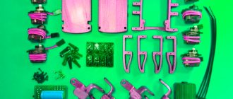
Full list of components
Required Components
| Component type | Component model | Price |
| Microcontroller | Teensy 3.2 | 19.80 |
| Engine | Tamiya 70168 | 9.25 |
| Motor Driver | DRV8835 | 4.49 |
| Spherical bearing | Tamiya 70144 | 5.99 |
| Reflector sensor | QTR-3RC | 4.95 |
| Wheels | Tamiya 70101 | 4.10 |
| Distance sensor | Pololu 38kHz | 5.95 |
| Printed circuit board | Elecro 10x10cm | 14.00 |
| Battery holder | Battery holder 2-AA | 0.79 |
| Total cost excluding delivery | $49.52 | |
Additional components
| Component type | Component model | Price |
| Wireless module | nRF51 Dongle | 52.39 |
| Connectors | Pin connectors | 5.00 |
Important! About small details
Speaking of “cogs”.
If you have encountered a similar problem and know how to make the assembly even more convenient, welcome to the comments. For now, I'll share my experience. Bolts and screws that are identical in function, but different in length, are quite clearly stated in the instructions, for example, in the middle photo below we see bolts P11 and P13. Or maybe P14 - well, that is, again, I'm confusing them again. =)
You can distinguish them: the instructions indicate which one is how many millimeters. But, firstly, you won’t sit with a caliper (especially if you are 8 years old and/or you simply don’t have one), and, secondly, in the end you can only distinguish them if you put them next to each other, which may not happen right away came to mind (didn't occur to me, hehe).
Therefore, I’ll warn you in advance if you decide to build this or a similar robot yourself, here’s a hint:
- or take a closer look at the fastening elements in advance;
- or buy yourself more small screws, self-tapping screws and bolts so as not to worry.
Also, never throw anything away until you have finished assembling. In the bottom photo in the middle, between two parts from the body of the robot’s “head,” there is a small ring that almost went into the trash along with other “scraps.” And this, by the way, is a holder for an LED flashlight in the “head” of the gripping mechanism.
Interaction: sensors
Line following and wall following require different sensors. Line-following sensors are usually reflectometers, which vary the output voltage depending on how much light is reflected from the ground. This is done using an LED and a photodiode or light sensor. Wall and obstacle detectors are usually distance sensors. Both types of these sensors were available in convenient DIP packages in the same shop as the motors, allowing me to save on shipping and solder them easily. Regarding the line sensor, I found a sensor with three sensors that allows the robot to be centered on the line at all times. Regarding the distance sensor, I decided to use a high brightness infrared sensor since in this project I was dealing with lower voltage than expected.
Build process
The robot comes with instructions without unnecessary words - just images and clearly cataloged and labeled parts.
The parts are quite easy to bite off and do not require cleaning, but I liked the idea of processing each part with a cardboard knife and scissors, although this is not necessary.
The build begins with four of the five included motors, which are a real pleasure to assemble: I just love gear mechanisms.
We found the motors neatly packaged and “sticking” to each other - get ready to answer the child’s question why commutator motors are magnetic (you can immediately in the comments! 
Important:
in 3 out of 5 motor housings you need to
recess the nuts on the sides
- we will later place the housings on them when assembling the arm. Side nuts are not needed only in the motor, which will form the basis of the platform, but in order not to remember later which body goes where, it is better to bury the nuts in each of the four yellow bodies at once. Only for this operation you will need pliers; they will not be needed later.
After about 30-40 minutes, each of the 4 motors was equipped with its own gear mechanism and housing. Putting everything together is no more difficult than putting together Kinder Surprise in childhood, only much more interesting. Question for care based on the photo above:
three of the four output gears are black, where is the white one? Blue and black wires should come out of its body. It’s all in the instructions, but I think it’s worth paying attention to it again.
After you have all the motors in your hands, except for the “head” one, you will begin assembling the platform on which our robot will stand. It was at this stage that I realized that I had to be more thoughtful with screws and bolts: as you can see in the photo above, I didn’t have enough two screws to fasten the motors together using the side nuts - they were already screwed into the depth of the already assembled platform. I had to improvise.
Once the platform and main part of the arm are assembled, the instructions will prompt you to move on to assembling the gripper mechanism, which is full of small parts and moving parts - the fun part!
But, I must say that this is where the spoilers will end and the video will begin, since I had to go to a meeting with a friend and had to take the robot with me, which I couldn’t finish in time.
Nuances of pedagogy
I did everything described above in my free time in the evenings.
In a leisurely manner, I spent about three weeks on the robot. This could have ended here, but I also promised to tell you about working with a child. What can be done at this age? Work according to instructions
We first checked each detail separately - LEDs, tweeter, motors, sensors, etc. There are a large number of ready-made examples - some right in the development environment, others can be found on the Internet. This certainly makes me happy. We take the code, connect the part, make sure that it works, then we begin to change it to suit our task. The child makes the connections according to the diagram and under some of my supervision. This is good. You also need to be able to work strictly according to instructions.
Order of work (“from particular to general”)
This is a difficult point. You need to learn that a big project (“make a robot”) consists of small tasks (“connect a sensor,” “connect motors”...), and those, in turn, consist of even smaller steps (“find a program,” “connect a board.” ", "download firmware"...). By performing more or less understandable tasks of the lower level, we “close” the tasks of the middle level, and from them the overall result is formed. I explained, but I think the realization will not come soon. Somewhere, probably, by adolescence.
Installation
Drilling, threads, screws, nuts, soldering and the smell of rosin - where would we be without it? The child received the basic skill “Working with a soldering iron” - he managed to solder several connections (I helped a little, I won’t hide it). Don't forget about the safety explanation.
Computer work
I wrote the program for the robot, but I still managed to achieve some favorable results.
First: English. They had just started it at school, so we were struggling to figure out what pishalka, migalka, yarkost and other transliterations were. At least we understood this. I deliberately did not use native English words, since we have not yet reached this level.
Second: efficient work.
We taught hotkey combinations and how to quickly perform standard operations. Periodically, when we were writing the program, my son and I swapped places, and I said what needed to be done (replacement, search, etc.). I had to repeat over and over again: “double-click select”, “hold Shift”, “hold Ctrl” and so on. The learning process here is not fast, but I think the skills will gradually be deposited “in the subcortex.” Hidden text
You might say that the above is almost obvious. But, honestly, this fall I had the opportunity to teach computer science in the 9th grade at one school. That's horrible. Students do not know such basic things as Ctrl + Z, Ctrl + C and Ctrl + V, selecting text while holding Shift or double-clicking on a word, and so on. This is despite the fact that they were in their third year of studying computer science... Draw your own conclusion. Third: touch typing. I entrusted the comments in the code to the child to type (let him practice). We immediately placed our hands correctly so that our fingers gradually remembered the location of the keys.
As you can see, we are still just getting started. We will continue to hone our skills and knowledge; they will be useful in life.
By the way, about the future...
How to become the life of the party with the help of a robot
Easily! As we continued assembling together, it became clear that assembling a robot on your own was a lot of
fun. Working on a design together is doubly pleasant. Therefore, I can confidently recommend this set for those who do not want to sit in a cafe having boring conversations, but want to see friends and have a good time. Moreover, it seems to me that team building with such a set - for example, assembly by two teams, for speed - is almost a win-win option.
The robot came to life in our hands as soon as we finished assembling it. Unfortunately, I cannot convey our delight to you in words, but I think many here will understand me. When a structure that you assembled yourself suddenly begins to live a full life - it’s a thrill!
We realized that we were terribly hungry and went to eat. It wasn't far to go, so we carried the robot in our hands. And then another pleasant surprise awaited us: robotics is not only exciting. It also brings people closer together. As soon as we sat down at the table, we were surrounded by people who wanted to get to know the robot and build one for themselves. Most of all, the kids liked to greet the robot “by the tentacles,” because it really behaves like it’s alive, and, first of all, it’s a hand! In short, the basic principles of animatronics were mastered by users intuitively
. This is what it looked like:
Circuit operation
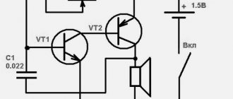
The diagram of a self-balancing robot based on the Arduino UNO board is shown in the following figure.
As you can see, the circuit is quite simple and in it you just need to connect the MPU6050 gyroscope and motor driver to the Arduino board, and also connect the motors to the motor driver. The circuit is powered by a 7.4V lithium-ion battery.
The Arduino board and the L298N motor driver module are directly powered via the Vin and 12V pins respectively. The voltage regulator built into the Arduino board converts the 7.4V input voltage to 5V, which powers the ATmega microcontroller on the board and the MPU6050 gyroscope. DC motors can be powered from 5V to 12V, in our case they will operate from 7.4V.
The pinout pinout for the MPU6050 gyroscope is shown in the following table.
| MPU6050 | Arduino pin |
| Vcc | +5V |
| Ground | Gnd |
| SCL | A5 |
| S.D.A. | A4 |
| INT | D2 |
The L298N motor driver pinout pinout is shown in the following table.
| L298N | Arduino pin |
| IN1 | D6 |
| IN2 | D9 |
| IN3 | D10 |
| IN4 | D11 |
The MPU6050 gyroscope communicates with the Arduino board via the I2C interface, so we used SPI pins A4 and A5 of the Arduino board to connect it. DC motors are controlled using PWM (Pulse Width Modulation) pins D6, D9, D10 and D11. The PWM signal in this case is necessary to control the rotation speed of the motors.
Troubleshooting
Upon returning home, an unpleasant surprise awaited me, and it’s good that it happened before the publication of this review, because now we’ll immediately discuss troubleshooting.
Having decided to try to move the arm through the maximum amplitude, we managed to achieve a characteristic crackling sound and failure of the functionality of the motor mechanism in the elbow. At first this upset me: well, it’s a new toy, just assembled, and it no longer works.
But then it dawned on me: if you just collected it yourself, what was the point? =) I know very well the set of gears inside the case, and to understand whether the motor itself is broken, or whether the case was simply not secured well enough, you can load it without removing the motor from the board and see if the clicking continues.
This is where I managed to feel real
robo-master!
Having carefully disassembled the “elbow joint”, it was possible to determine that without load the motor runs smoothly. The case came apart, one of the screws fell inside (because it was magnetized by the motor), and if we had continued operation, the gears would have been damaged - when disassembled, a characteristic “powder” of worn-out plastic was found on them.
It is very convenient that the robot did not have to be disassembled entirely. And it’s really cool that the breakdown occurred due to not entirely accurate assembly in this place, and not due to some factory difficulties: they were not found in my kit at all.
Advice:
For the first time after assembly, keep a screwdriver and pliers at hand - they may come in handy.
Creating a wireframe
There is no "ideal" way to create a frame. A compromise is almost always required. Perhaps you need a lightweight frame. But it may require the use of expensive materials or materials that are too fragile.
You may want to make a robust or large chassis. Although you understand that it will be expensive, difficult or difficult to produce. Your "ideal" frame or frame may be very complex. Making a robot frame may require too much time to design and build.
At the same time, a simple frame can be no less good. The perfect shape is rare, but some designs can look more elegant due to their simplicity. Perhaps other projects may attract attention due to their complexity.
What can be taught thanks to this set?
Self confidence!
Not only did I find common topics for communication with complete strangers, but I also managed to not only assemble, but also repair the toy on my own! This means I have no doubt: everything will always be ok with my robot. And this is a very pleasant feeling when it comes to your favorite things.
We live in a world where we are terribly dependent on sellers, suppliers, service employees and the availability of free time and money. If you know how to do almost nothing, you will have to pay for everything, and most likely overpay. The ability to fix a toy yourself, because you know how every part of it works, is priceless. Let the child have such self-confidence.
Control program
I don’t see the point in describing the code in detail, who needs it - the link is at the end of the article, everything is quite readable there.
But it would be nice to explain the general structure. The first thing we had to understand was that a robot is a real-time device. More precisely, to remember, because both before and now I still work in electronics. This means we immediately forget about calling delay()
, which they love to use in example sketches, and which simply “freezes” the program for a specified period of time. Instead, as experienced people advise, we introduce timers for each block. The required interval has passed - the action has been performed (increased the brightness of the LED, turned on the engine, and so on).
Timers can be interconnected. For example, the tweeter works synchronously with the flasher. This simplifies the program a little.
Naturally, we break everything down into separate functions (flashing lights, sound, turning, moving forward, and so on). If you don’t do this, then you won’t be able to figure out what’s coming from where and where.
Results
What I liked:
- The robot, assembled according to the instructions, did not require debugging and started immediately
- The details are almost impossible to confuse
- Strict cataloging and availability of parts
- Instructions you don't need to read (images only)
- Absence of significant backlashes and gaps in structures
- Ease of assembly
- Ease of prevention and repair
- Last but not least: you assemble your toy yourself, Filipino children don’t work for you
What else do you need:
- More fasteners, in stock
- Parts and spare parts for it so that they can be replaced if necessary
- More robots, different and complex
- Ideas on what can be improved/added/removed - in short, the game doesn’t end with assembly! I really want it to continue!
Verdict:
Assembling a robot from this construction set is no more difficult than a puzzle or Kinder Surprise, only the result is much larger and caused a storm of emotions in us and those around us. Great set, thanks
Brains: microcontroller
There are several different microcontroller platforms that are quite popular. Based on popularity, the obvious choice is some kind of Arduino. Other options: Teensy, Launchpad and Raspberry Pi. The Pi is too big and power hungry, and the Launchpad is too big. I have used Teensy in the past and it was a good experience. Teensy is a little more expensive than the Arduino Mini, but offers a much more powerful platform. The latest Teensy board features a Cortex M4, which is powerful enough for a simple robot. A bonus to the Teensy is a built-in 500mA regulator that can be used to power all sensors.
Making a robot Valli from paper
In order to glue the Valli robot , you will first need to print out diagrams of the parts that it consists of. It is better to print on a color printer, then the robot will be more beautiful and impressive. It is better to use thick paper; thin cardboard works well. If you don’t have such paper, then print the details on regular A-4 office paper and then stick it on cardboard.
Once the pieces are printed, start cutting them out. To do this, use small scissors or a utility knife.
At the last stage, all that remains is to glue all the parts together. To do this, it is better to use a glue stick, this will allow gluing more accurately.
Further development
The robot is made, drives, blinks and beeps.
What now? Inspired by what we have achieved, we plan to refine it further. There is an idea to make a remote control - like a lunar rover. It would be interesting, sitting at a remote control, to control the movement of a robot that is driving in a completely different place. But that will be a separate story... And at the end, in fact, the heroes of this article (video by clicking):
Thank you for your attention!
→ Link to code