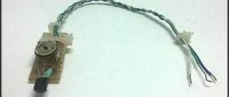
If you know how to solder, this little project will take you about 20 minutes. A homemade robot cockroach uses a vibration motor as its head, the motor is powered by a capacitor, which is also the abdomen of the insect, the specification indicates the following parameters of the capacitor: 2.8V 5F, you can buy one for 100-150 rubles.
You can use diodes or resistors as legs and antennae. All these components are soldered together on one small circuit board, which is also the thorax of the insect.
Since the microrobot uses a supercapacitor as its power source, we will need two AA batteries for power (as shown in the video above).
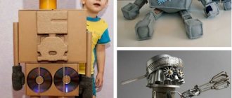
Bee
These tireless workers fly around over a trillion flowers every year, pollinating them and collecting healing nectar. One hive per season can bring its owner up to 150 kg of honey. Bees can “smell” the smell of honey plants, literally, from a kilometer away. They themselves synthesize special aromatic substances - pheromones, with the help of which they communicate with each other.
Not everyone knows that bees have 5 eyes – 3 regular and 2 faceted. Such a complex visual apparatus allows you to accurately navigate in space and promptly notice obstacles. However, bees have a keen sense of smell that helps them the most. It is so thin that beneficial insects are used to find explosives, and more effectively than sniffer dogs.
You can fold a classic origami bee according to the following scheme:
And this is a modular model:
Necessary equipment
We recommend that you prepare everything you need near you in advance - this way you will not be distracted from your work, which will increase your speed. You can use beads of any color - the main thing is that the shades combine well with each other.
So, you will need a base for embroidery - hard felt will be enough. Wire of such thickness that it can hold its shape well.A little cardboard, tulle, narrow lace. Three-millimeter sequins, beads and beads. They can be of various shapes and colors - the main thing is to ensure that they fit well together.
It is worth taking care of the base for the bug, as well as tools, such as a game, thread, scissors, and pliers.
Assembly drawing
All components are placed on a double-sided board measuring 170x80mm. It is quite possible to make it at home and use jumpers to make the entire top layer of conductors. All output components are located on the front side of the printed circuit board.
Printed circuit board from the front side
On the reverse side there are SMD components for the driver, PWM generator and clapper switch.
Printed circuit board from the back side
The motor holder bracket is attached to the assembled board with screws. Microswitches are installed in the front of the beetle on plastic ties.
Other beaded brooch options
In addition to the master class described above on how to make a brooch called “Bug” from beads with your own hands, you can also make other insect brooches from beads.
Beetle brooch made of beads Beetle brooch made of beads Beetle brooch made of beads Beetle brooch made of beads Beetle brooch made of beads Beetle brooch made of beads
On the Internet you can find a video on how to make a brooch from beads with a wide variety of insects. It is worth noting the decoration in the form of a ladybug (there are several options for making it), a scarab, and many fancy insects. There are also various animals, for example, a cute hedgehog, a cheerful frog and others.
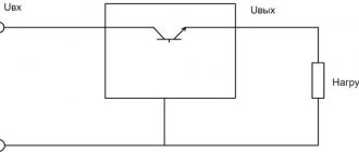
Structural scheme
In the initial state, the beetle always moves forward. This is set by a combination of engine signals. If one of the sensors is triggered, the trigger block (TRIGGER) enables the operation of the clock generator (CLOCK SOURCE) and the counter, which is included in the DIRECTION SELECTOR block. While counting, the beetle performs a sequence of actions to avoid an obstacle. First he stops, then pauses, pulls back, pauses, turns left or right, pauses again and resumes driving. On the fifth cycle of operation, the trigger is reset.
Depending on the triggered sensor, the beetle turns left or right. The movement direction selection block generates four motor control signals - two for each driver. The combination of logic levels of these signals allows you to rotate the motor forward or backward, or stop the motor. The beetle turns due to the fact that the wheels rotate in opposite directions.
The entire circuit is powered from two 18650 LiIon batteries connected in series, or from an external power source with a voltage of 7-9V. Power is supplied to the motor drivers via a CLAP SWITCH. This allows you to stop or resume movement by clapping your hands.
An adjustable PWM signal generator (PWM) is used to regulate the beetle's movement speed.
Block diagram and signals
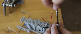
Prototype:
Before we begin assembling the robot, we will check the functionality of the hardware and software. Upload the sketch to the microcontroller, change the codes in the program in accordance with the table you created. Press the control buttons on the remote control, check whether the servomotors react and that everything works. Check the functionality of the model not only with USB power, but also with battery power.
Preparation
It's great if you are familiar with the Arduino platform. If not, no problem. Building a Ringo robot is a great way to fix this. Get started with our online Arduino tutorials for beginners.
Components Needed to Develop a Beetle Robot
Tools you'll need
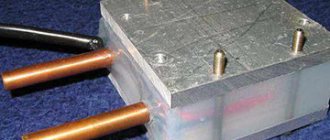
Components required for the project: Arduino Uno with USB cable, box for one 9V battery, 9V battery (or 7.2-8.4V battery), three small analog servos, one infrared (IR) receiver, mini-bradboard, connecting wires, steel wire (diameter 1.5 - 2 mm), 2-3 ordinary metal clips. Tools will also come in handy.
Settings
All key switches must be in the SIGNAL position for proper operation. The XP3 connector must be set to the SWITCH position for the driver power control to work via the cotton switch. If it does not function, you can set the switch to the V_BAT position. Then the driver will always be active. Jumpers XP1, XP2 are responsible for controlling the speed of the motors. In the PWM position it will be possible to adjust the PWM resistor R8. If you set the jumper to the Enable position, the motors will always run at maximum speed. Resistor R2 can be used to regulate the duration of stops and movements when avoiding obstacles.
How to connect IR receiver to Arduino
The project uses an IR receiver and an IR transmitter (this could be your TV remote).
Let's learn how to receive commands from an IR remote control. You need to read and remember the signal code in order to later use it to control the robot. Take an Arduino Uno, a board, connecting wires and an IR receiver. Assemble the circuit as in the photo.
Connecting IR Receiver to Arduino UNO
Connection diagram for IR receiver to Arduino UNO
This is the TSOP2136 IR receiver wiring diagram. If you use another receiver, see its specifications.
Now the code from GitHub. Open the Arduino IDE and the project /ir_receiver/ir_receiver.ino. First line of code:
This means that the sketch uses a special library IRremote.h, which implements the functionality of receiving and sending IR signals.
IRremote.h is not part of the Arduino IDE and will need to be installed. This is an open source project with a GNU license, so we can use this code for our robot. Open Serial Monitor and check the transfer speed. Set the speed to 9600. Take the IR remote control and start pressing the buttons. If the assembled model works, you see the codes in Serial Monitor.
Different manufacturers have different codes, and the codes may also differ for different models of IR remote controls. In order not to have to understand these codes and to simplify the task, we will simply write down the correspondence of the codes to the pressed buttons that we will use. Some codes correspond to pressing and holding the button again - we will not use them.
Our robot can perform 13 commands:
- Move forward.
- Move backward.
- Turn left.
- Turn right.
- Moving forward with a left turn.
- Moving forward with a right turn.
- Driving backwards with a left turn.
- Moving backwards with a right turn.
- Stop.
- Setting speed 1 (slow).
- Setting 2nd speed.
- Setting 3rd speed.
- Setting the 4th speed (fast).
Select the buttons on your remote control for the appropriate commands. For example, buttons 1-9 for the first nine commands and colored buttons (red, green, yellow and blue) for the last four.
Now press the appropriate button and write down the corresponding unique codes.
List of elements
You can download it as a separate document from the link at the end of the article.
- Resistor, R1, MF-0.125-68k, 1 pc.
- Trimmer resistor, R2, CA9MV 100k, 1 pc.
- Trimmer resistor, R8, CA9MV 50k, 1 pc.
- Resistor, R3,R16,R17,R19-R24,R66, MF-0.125-1k, 10pcs
- Resistor, R18,R68,R78, MF-0.125-10k, 3pcs
- Resistor, R27-R29,R31,R35,R36,R38-R42,R44,R47,R50-R52,R56,R59,R62-R64,R74-R76, 0805, 10k, 24pcs
- Resistor, R4-R7,R9-R13,R69, 0805, 20k, 10pcs
- Resistor, R14, 0805.1M, 1 piece
- Resistor, R60,R61, 0805, 470k, 2pcs
- Resistor, R15,R25,R26,R30,R32-R34,R37,R43,R45,R46,R48,R49,R53-R55,R57,R58,R67,R70-R73,R77, 0805, 1k, 24pcs
- Resistor, 1W, 1Ohm, R65, MF-1-1, 1pc.
- Capacitor, C1, X7R, 0.01uF, 10%, 50V, 1pc
- Capacitor, C4-C6,C15-C18,C20,C22,C24-C30, C34-C37, 0805, 0.1uF, 20pcs
- Electrolytic capacitor, C2,C31, 10uF-16V, 2 pcs
- Output capacitor, C3,C7-C14,C32, X7R, 0.1uF, 10%, 50V, 10pcs
- Electrolytic capacitor, C19,C21,C33, 470uF-16V, 3pcs
- SO-8, DA1, LM358DT, 1 piece
- DIP-8, DD1, NE555P, 1 piece
- DIP-14, DD2,DD8, CD4013BE, 2 pcs
- DIP-14, DD3,DD5,DD6,DD7, CD4001BE, 4pcs
- DIP-16, DD4, CD4017BE, 1 piece
- Diode, VD1-VD5, 1N4001, 5 pcs.
- Diode, SMA, VD6-VD9, S1M, 4pcs
- Transistor, TO-92, VT1,VT23, BC547BTA, 2pcs
- Transistor assembly, SOIC-8, VT2,VT3,VT12,VT13,VT24, IFR7105, 5pcs
- Transistor, SOT-23, VT4-VT7,VT17,VT17,VT19,VT21, BC817-40, 8pcs
- Transistor, TO-92, VT22, BC557BTA, 1pc.
- LED, 3mm, HL1,HL3-HL8,HL13, FYL-3014ED1A, 8pcs
- LED, 0805, HL2,HL9-HL12, KP-2012SGC, 5pcs
- Electret microphone, BM1, EM-6050(p), 1 piece
- Plug for board, XP1,XP2,XP3, PLS-40, 0.3pcs
- Terminal, XS1-XS5, DG340-3.81-02P, 5pcs
- Switch, SOIC-8, SA1,SA2, DMR-06-V, 2pcs
- Battery holder, E1,E2, LiIon, 18650, 2pcs
- Microswitch, KMSW-14, 2 pcs.
- Jumper, 2.54, 3pcs
- Socket DIP-8, SCS-8, 1 piece
- Socket DIP-14, SCS-14, 6 pcs
- Socket DIP-16, SCS-16, 1 piece
- Handle for CA9V, CA9MA5, 2 pcs
- Wheel, 2 pcs
- Motor with gearbox, 2 pcs.
- Printed circuit board, 1 piece (files for manufacturing at the end of the article)
- M3x30 screw zinc, 4 pcs
- M3x10 screw zinc, 4 pcs
- Nut M3, 8 pcs
- M3x10 mother-father stand, 1 piece
- Nut M3 plastic, 1 piece
- Heat-shrink tubing
- Mounting wire
- Cable ties
- 3D printed bracket (link to download the model at the end of the article)
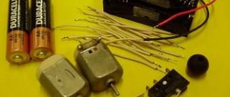
This is what the complete set of components for this device looks like:
Robot beetle. Set of components
Schematic diagram
The picture is clickable, and at the end of the article you can find a download link in pdf format.
Schematic diagram
Please note that all blocks of the device are arranged block by block. This allows them to work autonomously and clearly see the functionality of the pieces of the circuit. You will find additional comments on the operation of the circuit in the device assembly instructions.