Haven't purchased one yet? Then let me introduce a homemade device for testing the rotor of electric motors, which was made due to the need to test various equipment such as drilling machines, grinders and washing machines, vacuum cleaners and so on. Of course, there are special devices on sale for performing such checks, but buying such a device is pointless, because assembling it yourself does not cost a penny.
Device for finding turn-to-turn short circuits in generators/starters
Welcome to ChipTuner Forum.
Theme Options
Sergrider
Sukhov
You need two 2.15 amp chokes from DRL or DNA lamps. And a 10-20 microfarad capacitor. If you're interested, I'll take some photos at work tomorrow and post them here.
Added after 16 minutes
Sergrider
Kanai
Sukhov
Bashkirov Vladimir
Anchor Testing Device
The device is used to test for interturn short circuits in the armatures of DC motors and (generators), as well as to test pole coils.
Operating principle of the device
The device is an alternating current transformer that has only a primary winding, with a magnetic gap in the core. The armature being tested is placed in the core gap, and its winding becomes the secondary winding of the transformer. If there are short-circuited turns in the armature being tested, since the turns are distributed in groups, a local magnetic supersaturation of the iron occurs, which is easily detected by the rattling of a steel plate placed on the armature iron above the turn (for example, a hacksaw blade). We rotate the armature in the magnetic gap so that the plate is above the different coils. Where there is an interturn closure, the plate begins to vibrate noticeably. A closed loop theoretically begins to heat up (though, as a rule, on large anchors, too slowly for heating to be practically detectable).
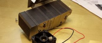
We need two such chokes and a 10-20 uF capacitor at 400 V.
Next, we disassemble the chokes. We beat off the base with a hammer and use it to hit the core along the edge from below. Reminds me of disassembling the universal joint. We get a bunch of such pieces of iron.
We only need these.
We place them as they were in the throttle and insulate them well. In several layers. We pay special attention to the corners of the core. The operation of the device and your safety depend on the quality of the insulation.
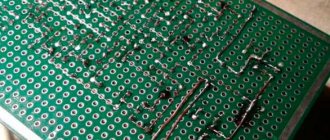
Next, we take the removed inductor winding and wind it turn to turn. We insulate each layer of winding with electrical tape. You can also wind it on vertical sections of the core. When the first one ends, solder the second one to it and continue winding. The photo shows the wire for demonstration purposes. It is in PVC insulation. Upon completion of winding, carefully insulate the windings. This is roughly how it should work out.
We connect the capacitor with the winding in series. To limit current. The core can be made long. Taking iron from two chokes.
This is how the anchor should lie.
To find a short circuit, it is convenient to use a hacksaw blade for metal.
Also, using a milliammeter, you can check the winding for open circuits (bad soldering in the cockerels, etc.). To do this, you need to connect the milliammeter to the adjacent lamellas of the armature, turning the armature in the PPY groove by 1 lamella, between connections. In a working armature, the current from all adjacent lamellas will be the same. A sharp increase in current (or drop, if there are several breaks) indicates a break between these lamellas. When checking, it is necessary to maintain a constant angle of contacts of the milliammeter relative to the poles of the device, otherwise the readings on different pairs of lamellas will be different even on a working armature.
And further. If you put the demonstration winding like in the photo, you will get a regular transformer. Anyone interested can download photos and videos. The quality is really not very good.
Source
Short circuit detection methods
Let's consider ways to detect a short circuit in the armature or stator winding. At least four of them are known:
1.1. Contact-by-contact check of winding resistance with an ohmmeter. A sequential resistance measurement is carried out at the collector terminals, which requires a lot of working time. A shorted coil gives a resistance value close to zero.
1.2. The method of alternating electromagnetic field of the inductor. The choke is made (usually homemade) from a large W-shaped or toroidal transformer. The armature being tested is placed in the throttle cone and rotated 360°. When the armature groove, in which there is a short circuit, is combined with a gap in the magnetic circuit of the inductor, a hum or rattle is heard. The dimensions and weight of the device are not for a nerd, look at the samples on YouTube. The stator short circuit cannot be determined with this device.
Checking the armature for interturn short circuit
Electrical machines consist of a rotor and a stator. The stator consists of stationary windings placed in a housing. The anchor is a moving part, so as a rule, particles of dirt and grease get on it and, under the influence of temperature, an oxidized coating is formed. It can cause malfunction or failure of the rotor of an electrical machine. It is detected by visual inspection. Carbon deposits can cause interturn short circuits in the armature. As such, the motor rotor does not wear out under normal operating conditions. Over time, only current-collecting brushes must be replaced if their length no longer corresponds to the permissible size. However, prolonged loads cause heating of the stator windings, which ultimately contributes to the formation of carbon deposits. Interturn closure of the armature can occur due to mechanical damage. The presence of chips, dents, scratches and cracks on rubbing surfaces is unacceptable. A short circuit between the turns of the armature windings occurs in the event of failure of the bearing units. Then the anchor warps, which leads to damage to the lamellas. Another cause of short circuiting is exposure to moisture. When water drops hit metal surfaces, the corrosion process begins. Rust makes it difficult for the armature to rotate, current loads increase, heating occurs, as a result of which the solder can peel off, which in turn, during long-term operation, can lead to an interturn short circuit.
Device
To correctly diagnose armature faults, it is important to know the device and the principle of its operation . The main elements of the armature are a round core, consisting of a set of electrical steel plates and a winding wound into its grooves in a certain way. Two armature windings are placed in each of the grooves according to a special pattern . The first and last turns of one of the windings are in the same groove and are closed to one lamella.
Rotor for Makita angle grinder 9069 MAX. Photo 220Volt
The core is pressed onto the rotor , which rotates under the influence of forces arising in the electromagnetic field formed by the armature windings and the stator coils working in tandem with it. In grinders, the anchor is an assembly unit with a drive gear located at one end of the shaft, and a commutator unit at the opposite end.
ƒ↓ — Armature testing device (APD)
“By admitting our mistakes, we find the source of strength.”
I decided to make a device for checking anchors for short-circuited turns and so on. It will be useful if you decide to repair the commutator motor and check whether it was wound correctly. A very useful thing and was once produced in the USSR. But now you won’t find it during the day with fire.
We won’t go into complex formulas, I’ll try to explain in a moment what I did. I will split the article into 2 parts. "Part one. Magnetic core." "Part two. Electricity". Then I will explain why there are 2 parts.
Part one. Magnetic core.
Firstly, we need a magnetic circuit, or in other words, a stator from the vacuum cleaner motor. Then we need to cut out a part in one side of it at an angle of 90 degrees, where the anchor itself will lie for testing. You can use a grinder, a saw, a spoon - whatever is more convenient for you.
PS The device on the stator of a vacuum cleaner is inspired by a topic on one forum. The original is here. Thanks to the author for the push in the right direction.
Electrical cardboard from a different engine, but in which the windings were once placed.
And we wrap it in one layer on the magnetic circuit, securing the whole thing with tape:
Then we need cheeks so that the wire rests on the sides and we get a full-fledged coil. We cut them out of plywood, having previously calculated the dimensions.
And use a chisel to remove the excess. You can clean it up a little with sandpaper.
Don’t forget to take into account the angle of the stator and adjust it with the same sandpaper - a small angle on the cheeks themselves
It is desirable that the cheeks themselves become tight on the magnetic circuit.
If not, take a notebook and cut a piece of sheet to the size of the cheeks and wind it with sizing. Until the wall becomes more or less tight.
We insert the cheeks and glue them with glue. I used almost half a pack of PVAK. I glued and filled it about a dozen times. The next morning everything was ready.
That's all for the Magnetic Core part.Part two. Electricity.
(According to calculations (number of turns = 50 / S * 220V) on this site, I calculated the required number of turns, it turned out to be 660. But I didn’t like that this applies to all thicknesses of wires! How so?? The site seems to be good, but I’m in the calculations I doubted it, or maybe I misunderstood something.)
I spent about 4-5 hours. Turn by turn, diligently. Believing less and less in success. It turned out about 800 turns.
Having finished, I went to bed and left it until the morning.
I checked it today. I set the tester and ammeter to the required modes to take readings.
20 Volts - about 1 Ampere
50 Volts - 2 Amps
And taking a risk, realizing that he was right yesterday, he applied a hundred volts:
100 Volts - 4.5 Amperes.
So what kind of 220 are we talking about? It will definitely “dissipate”, this wire.
Have you forgotten how much it was supposed to be? No more than 1.25A, but here 4.5A only at 100 Volts. The experiment ended in smoke from under the electrical tape, melting of the wire and complete failure. But it’s better than sitting and looking out the window with a drunken hare, drinking endlessly.
And now about the Parts. The “Magnetic Circuit” part is completely suitable for implementation. But as for the “Electricity” part, I think the mistake here was that you need to increase the resistance - in other words, take enough wire to withstand 220 Volts.
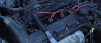
There is already a suitable donor, some old inductor from a TV with a resistance of 240 Ohms, wire diameter 0.08 mm. I think it will hold up. Or maybe not. So to be continued.
Source
How to detect shorted turns
Detection must be a top priority. These negative phenomena manifest themselves in half the cases during self-assembly of the transformer, mostly during the manufacture of loop coils and chokes. It is imperative to identify and eliminate the defect, since the existing defect will negatively affect the efficiency of the device, lead to a breakdown that is difficult to repair, and pose a risk to the safety of the employee servicing the device.
The determination occurs initially by external signs. If there are visible changes in technical indicators without a reason for this, or a crackling sound is heard, then diagnostics should be carried out. The cause is coil defects. For example, the application of turns in a cross rather than symmetrical manner, the use of low-quality winding from an unverified manufacturer, damage to the insulation during work or when moving the device, mechanical damage. But an effective way to find the turn is not to use electronic devices. Only with their help can one determine the source of damage to the winding and identify its characteristics.
Short-circuited turn in a transformer: what is it?
A short-circuited defect represents an increase in the flow of magnetic energy. This happens when the electromagnet is turned on at average transformer voltage levels. A drop in flow is observed when disconnected.
Located on two core rods. But depending on the structural components and characteristics of the transformer, it changes.
Its peculiarity is that it is formed by the main energy flow. The parameter is set towards the lag, and the angle observed between the primary and secondary currents decreases. In this case, not only the flow value changes, but the phase, which is an important indicator. Special mechanisms are required to determine this angle.
Tags: machine, anode, beat, sconce, view, generator, house, , sign, like, capacitor, circuit, crown, , magnet, voltage, connection, rule, check, wire, start, , work, size, calculation, rib , resistor, repair, row, light, LED, resistance, stabilizer, circuit, ten, type, current, transistor, transformer, , phase, effect, armature
Mechanism of coil formation
The mechanism for the formation of vortices in a transformer is standard for any type of equipment. The total flow during passage is divided into the first flow, which is distributed over planes that are not covered by the pole turns. The second flux of the electromagnet is on a plane that belongs to the square. At the second, an emf is formed, leading to a current pulse. In this case, an angle of a certain value arises, which is determined by the inductance.
Simultaneously with the passage of the flow, an attractive force arises. It consists of two components that are shifted in time. The pulsation (amplitude relationships) is determined purely by the shear angle that occurs between two flows in the area of action. The angle never exceeds 90 degrees. Typically its value lies between 50 and 80 degrees. This is explained by the fact that it is impossible to achieve a shift of flows at a right angle.
Why is it dangerous for short-circuited turns to appear in a transformer winding?
The appearance on the winding is considered an equipment defect that should be eliminated. The electrical diagram indicates that the confirmed part of the winding is the primary. The one with them is secondary. To eliminate defects, methods are used that are based on knowledge of the parameters of the emerging magnetic coupling between parts of the winding.
The action of the pulse voltage is inextricably linked not only with the damaged part of the winding. The impact affects the operation of the primary part, which has no defects. The effect of short-circuited circuits manifests itself primarily in sudden and unconditional voltage surges
Note that:
- to eliminate the problem, it is necessary to calculate the coil parameters;
- if the characteristics of the primary and secondary turns are similar, then the voltage surge will be maximum;
- identical characteristics of the turns lead to an increase in the dissipation coefficient.
As a result of the presence of short-circuited circuit turns, voltage surges occur. But this is not the only serious problem that requires consideration and solution. The secondary winding is affected due to magnetic flux dissipation, and a short circuit occurs in this part. The phenomenon threatens the failure of the structural components of the mechanism and those devices that it powers (at least their simultaneous disconnection from the network or transfer to the atomic mode of operation from batteries). There is also a risk of electric shock. Of course, transformer diagnostics (mandatory visually and using a device) is a mandatory method of industrial safety.
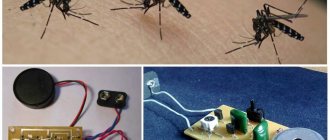
How to get bipolar power from unipolar power - an artificial midpoint
One of the biggest disadvantages of this circuit is the bipolar power supply. It is more practical and convenient to power the turn-to-turn short circuit tester from a Krona battery (9 V) and form an artificial midpoint. Using a simple circuit, the operation of which is described in the book “Voltage and Current Stabilizers on ICs (SI)” by B. Uspensky, you can obtain an artificial midpoint.
Of the parts used in the diagram:
- operational amplifier: mc34072 (or any other analogue like LM393)
- transistors SS8050 and SS8550 (a weaker pair is also possible, with an operating collector current of at least 200-300 mA)
- electrolytic capacitors 22 uF with an operating voltage of 16 V.
Attention! When setting up a circuit, in no case should you arrange a short circuit with a midpoint; one of the transistors will instantly fail, and the op-amp will also fail