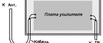
Homemade variable capacitor
Recently, it has become increasingly difficult to purchase variable capacitors.
I encountered this problem when creating a magnetic antenna: I was not satisfied with the high cost of vacuum capacitors, and I was not satisfied with the rusty appearance of used KPEs. In addition, KPIs from old receivers have a small gap between the plates and, when used in magnetic antennas, are pierced with high voltage. So I decided to make a homemade KPI. There were a lot of designs on the Internet, but the article that interested me the most was https://www.qsl.net/n4dfp/buildcaps.html. Actually, based on this article, the capacitor was made with minor modifications. So, the first thing we did was find a sheet of aluminum. It was found in a DIY store in the form of a sheet from a barrel of yogurt (0.3-0.4 mm thick). Blanks were cut from the sheet using scissors according to the drawings:
Drawings in SVG format can be downloaded from the link.
In total, 17 stator plate blanks were cut, and 16 rotor plates. All the plates were straightened, then 6 mm holes for screws were drilled in the right places. I recommend drilling workpieces of the same type at once, holding them in a vice. After drilling, the blanks were stripped of paint and the protective layer (the yogurt sheet was painted with advertising inscriptions on one side and a food layer on the other side). The end result was a bunch of stuff like this:
The side walls of the capacitor measuring approximately 100x70 mm were cut out of plastic.
To fasten the plates, I used M6 bolts 110 mm long, M6 nuts 4.5 mm thick, and washers.
The fastening of the plates is shown schematically in the figure (side view):
The first stator plate is secured through 3-4 washers (depending on their thickness) to ensure the required gap between the rotor and stator plates, and is clamped with nuts. The first rotor plate is clamped with nuts on both sides, while a small gap is provided between the side wall and the fastener so that the bolt with the rotor plates rotates freely in the hole.
On the opposite side wall of the capacitor it is necessary to implement a current collector and a spring element. I combined the two functions into one using a curved plate made from the same aluminum sheet and a foam plastic sticker:
After assembly, we finally straighten the plates and achieve the same distance between the plates at any rotor position.
The result was a capacitor with a capacitance range of 7-330 pF. The materials cost less than $10.
Source
Some features and tips when working from a household network of 220 V
When using asynchronous electric motors designed for an operating voltage of 380 V in the domestic sphere, by connecting them to a 220 V network, you lose about 50% of the rated power of the motors, but the rotor speed remains unchanged. Keep this in mind when choosing the power needed for the job.
Power losses can be reduced by using a “triangle” connection of the windings; in this case, the efficiency of the electric motor will remain somewhere at the level of 70%, which will be significantly higher than when connecting the windings “star”.
Therefore, if it is technically feasible to change the star connection to a delta connection in the junction box of the electric motor itself, then do it. After all, purchasing an “additional” 20% of power will be a good step and help in your work.
When choosing starting and operating capacitors, keep in mind that their rated voltage must be at least 1.5 times greater than the mains voltage. That is, for a 220 V network, it is advisable to use containers designed for a voltage of 400 - 500 V for startup and stable operation.
Motors with an operating voltage of 220/127 V can only be connected as a star. If you use another connection, you will simply burn it when starting up, and all that remains is to scrap it all.
If you cannot find a capacitor used for start-up and operation, then you can take several of them and connect them in parallel. The total capacity in this case is calculated as follows: Total = C1+C2+....+Sk, where k is the required number.
Sometimes, especially under heavy load, it overheats greatly. In this case, you can try to reduce the degree of heating by changing the capacitance Cp (working capacitor). It is gradually reduced, while checking the engine heating. Conversely, if the operating capacity is insufficient, then the output power produced by the device will be small. In this case, you can try increasing the capacitor capacity.
For a faster and easier start-up of the device, if possible, disconnect the load from it. This applies specifically to those engines that have been converted from a 380 V network to a 220 V network.
Homemade KPIs made from foil fiberglass
Variable capacitors, also known as variable capacitors or variable capacitors, are used in many devices. They are needed in generators, antenna tuners, some types of antennas, and much more. Let us pay attention to the fact that in amateur radio communications, for example, a transceiver can easily output 25 W or 100 W, but the maximum allowed power is 1000 W. It is clear that publicly available small KPIs are completely unsuitable here, and you simply won’t find the KPIs needed for such capacities in the store.
Suitable large KPIs from old radio equipment can be purchased on Avito and radio amateur message boards. But the prices there are often not low, the capacitors are rarely labeled with their capacity, it is not possible to find two or more identical capacitors, plus there are risks and inconveniences associated with buying them in person. Meanwhile, making a variable capacitor at home is not so difficult.
I got the idea from the 2003 article Build Your Own Transmitting Air Variable Capacitors by David Hammack, N4DFP. In his article, David uses copper sheets, which I did not have. But I figured that copper on a one-sided foil PCB, which I have in abundance, would work just as well. Why not try it?
I’ll show you right away what I ended up with. Front view:
The capacitor has five rectangular plates measuring 20 x 50 x 1 mm, secured with two long M3 bolts. The plates are separated by nuts. Four more semicircular plates with a radius of 25 mm are mounted on one M3 bolt. This bolt can be rotated using a potentiometer knob, which I glued to the bolt using epoxy glue. All this equipment is supported by a frame made of two rectangular pieces of sheet plastic measuring 30 x 50 mm. To connect to the moving plates I used thick copper wire bent into a loop. The wire fits tightly to the rotating bolt and is secured to the capacitor frame using hot-melt adhesive. The drop of solder, which can be seen in the second photo, serves to limit the angles of rotation of the handle. It is clear that everything would work without her. But I wanted the handle to have some extreme adjustments, and not just spin in all directions.
Fun fact! Textolite with a thickness of 1 mm can be cut with ordinary paper scissors. And the coil of solder standing on my table very fortunately turned out to be exactly 25 mm in diameter - I traced it around it.
The capacity of such a craft varies from 13 to 53 pF. By increasing the area of the plates or their number, you can get at least 1000 pF. I don’t think anyone will need larger capacitor trimmers. But such a capacitor will not be very convenient, both due to its large size and the fact that a slight turn of the knob will lead to a large change in capacitance.
A possible solution is to use the capacitor described above only for fine tuning, and use fixed capacitors for coarse tuning. The latter can be connected in parallel by switching toggle switches with two contact groups.
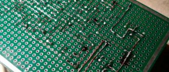
An example of a homemade fixed capacitance capacitor:
The capacitor consists of six plates 25 x 50 mm. The plates were glued together using epoxy glue. All even plates are connected to each other, and all odd plates are similarly connected. The capacitance of the capacitor is 270 pF. The practical value of such capacitors is apparently not very high, since high-voltage fixed-capacitance ceramic capacitors are readily available and inexpensive. However, let's look at them too, in case we ever need to work with very high voltages.
Fun fact! An alternative way to make a fixed capacitor is to simply take a piece of coaxial cable. A typical RG58 cable has a linear capacitance of about 100 pF per meter.
The dependence of the capacitance of the capacitor on the number of plates is as follows:
It can be seen that the capacitance increases in proportion to the number of dielectric layers up to the measurement error, which is in accordance with the theory. Using the first line, just for fun, you can calculate the dielectric constant of the PCB used:
This converges with an expected value of 4.4 to 4.7.
StackExchange suggests that to break through such capacitors, you need at least 3 kV per 1 mm of distance between the plates - this assumes that the current will flow through the air. To be on the safe side, it is recommended to use half of this value as the maximum voltage. The breakdown voltage can be increased by increasing the distance between the plates. But, as can be seen from the above formula, in this case the capacity will suffer, and the area and/or number of plates will have to be increased. A more practical solution is to etch 3mm of copper along the edge of the plates. Then the breakdown voltage will be about 20 kV - the breakdown voltage of 1 mm of PCB or 7 mm of air.
What the maximum voltage across the capacitor will be depends on the circuit in which it is planned to be used. This needs to be modeled or calculated every time. But in order for it to exceed the safe 10-15 kV, you will have to try. In this case, you can always simply increase the distance between the plates and use thicker PCB.
Fun fact! It goes without saying that there is nothing stopping you from delegating the manufacturing of capacitor components to your favorite PCB manufacturer.
As you can see, everything turned out to be quite simple. The obvious advantages of homemade KPIs are low cost and availability. You can make as many capacitors exactly as you need. As for the time it will take to make a capacitor, I think it is comparable to the time you will spend searching for a ready-made one, as well as negotiating with its seller.
Addition: Sheet aluminum will probably be a more suitable material for homemade KPIs than fiberglass.
Source
Connection diagrams for operating voltage 220 V
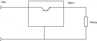
Due to the fact that there are two main options for connecting electric motor windings, there will also be two circuits for supplying a household network. Designations:
When connected to a 220 V network, three-phase electric motors have the opportunity to change the direction of rotation to the opposite. This can be done using the “P” toggle switch.
Attention! The direction of rotation can only be changed when the supply voltage is turned off and the electric motor is completely stopped, so as not to break it.
“Сп” and “Ср” (working and starting capacitors) can be calculated using a special formula: Ср=2800*I/U, where I is the current consumed, U is the rated voltage of the electric motor. After calculating Cp, you can select Sp. The capacity of the starting capacitors should be at least twice as large as that of the Average. For convenience and simplification of choice, the following values can be taken as a basis:
Where M is the rated power of the electric motors used, Cp and Sp are working and starting capacitors.
Design
Rice. 1. Drawing and design of a homemade variable capacitor with an air dielectric.
Designations in the figure:
The KPI device is shown in Fig. 1. It consists of a stator (parts 1, 12), a rotor (parts 5, 6, 8, 18, 19) and a housing (parts 2, 10, 11, 16, 17). Its capacity depends on the angle of rotation of the rotor relative to the stator, i.e., on the mutually overlapping area of the rotor and stator plates, their number and the air gap between them.
The stator plates 1 are secured by soldering to clamps 12, which, in turn, are secured in the holes of the side strips 16 of the KPI housing. The rotor plates 5 are soldered to the roller 6 and the retainer 8. The roller 6 rotates in bearings 14, secured to the bars 16 with screws 15.
When manufacturing KPIs, blanks of identical parts (rotor and stator plates, bearings 14, strips 16) are recommended to be processed together, combining them into packages using rivets or screws with nuts (for this purpose, holes with a diameter of 2.6 mm are provided in the rotor plates).
Of course, the shape of the plates, their number and the gap between them may be different; here, a lot depends on the capabilities and experience of the radio amateur; for example, it is hardly worth taking on immediately the manufacture of a capacitor with a gap of less than 1 mm in the absence of sufficient experience in plumbing.
Rice. 2. Appearance of the finished KPI.
Before assembling the rotor and stator, roller 6, clamps 8, 12 and soldering points on the plates (belts 2.3 mm wide around the holes for the roller and clamps) must be tinned.
In addition, you should prepare technological gaskets with dimensions of 35×35 mm cut out of corrugated cardboard, with a thickness equal to the air gap between the plates (i.e. 2 mm) (their number should be about a dozen more than the number of plates).
The choice of gasket material is due to the low heat capacity of corrugated cardboard, which facilitates the process of soldering the plates to the clamps. Next, straps 2 and 11, bearing 14 and current collector-limiter 7 are screwed to the upper (according to the figure) side strip 16. A hole is drilled in roller 6 for pin 19.
Having placed four or five cardboard spacers on its inner side, put the first rotor plate on the roller 6, put the next spacer on it, then put the first stator plate on the protruding ends of the clamps 12, put the next spacer, put the next rotor plate on the roller, etc. d.
When the number of rotor plates reaches three or four, a retainer 8 is inserted into their holes with a diameter of 3.3 mm, and subsequently each subsequent rotor plate is placed on both the roller 6 and the retainer 8.
Having installed the last stator plate in place, screw the second strip 16, insert the last few corrugated cardboard technological spacers into the gap between it and the stator plate, and if necessary, remove the excess gap between them with additional spacers of the required thickness.
The relative position of the rotor and stator plates is fixed with solder, heating the places where they are soldered to the roller and clamps with a powerful soldering iron.
The materials of the KPI parts and some technological instructions for its assembly are contained in the caption to Fig. 1. The appearance of one of the practical design options is shown in Fig. 2.
S. Dolganov, Barabinsk, Novosibirsk region. R-12-2016.
Source
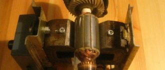
My Tesla laboratory. Variable capacitor.
This product is not completely independent.
This is only part of a more complex device, a model that is intended to test the technology. But the recent publication by hamster76 - a wonderful radio receiver showed me that this development is worth sharing. That’s why I’m writing to “Help the Steam Master.” In his publication, hamster76 talked about his problems with a damaged capacitor, but a variable capacitor is a Tesla device in itself! A Teslapunk capacitor may well decorate any device.
In the 20s, of the two methods of tuning the receiver - changing the inductance and changing the capacitance in the oscillating circuit, preference was given to changing the inductance. The first reason for this is theoretical: such a circuit potentially makes it possible to obtain a higher quality factor of the circuit and, as a consequence, better radio reception qualities. The second is technological. A variable capacitor is a complex mechanical device that requires high precision manufacturing. Already in the 30s, the situation changed - on the one hand, the technical capabilities of the radio industry increased, on the other hand, the spread of the superheterodyne reception circuit required synchronous restructuring of two circuits at the same time, and a dual variable capacitor turned out to be easier to manufacture than a dual variator. From then until the very end of the 20th century, a variable capacitor became an almost mandatory element of any radio device.
The main requirements for a capacitor are: 1) Continuity of electrical contact. At moments when the capacitor “comes off” from the circuit or, conversely, “short-circuits,” the radio listener hears very unpleasant clicks. 2) Smooth ride. With poor mechanics, it is very difficult to tune in to a station and “maintain the wave” in the future. 3) Large range of tunable capacity - allows you to capture more stations. 4) Low minimum capacity.
In order to avoid the problem of poor rotor contact, a contactless interaction scheme with the stator is used. The rotor plates are not connected anywhere, they interact with the stator only through the capacitance of the additional plates, this avoids the problem of poor contact. When the rotor turns, the capacitances between the plates are redistributed, and the total capacitance of the capacitor changes.
This design has disadvantages: the size of the plates is larger than in other schemes, the nonlinearity of the change in capacitance when the rotor is rotated, and the small “working range” of rotor rotation. The angle between the positions of maximum and minimum capacity is only 90 degrees.
But the design is very simple, without moving electrical contacts. In addition, the symmetry of the design greatly facilitates the design of the rotary axis.
The capacitor consists of a wooden base - a stator and a handle rotating on an axis - a rotor. They are cut from the board using crowns and turned on the axis of the drill. The stator diameter (this, however, is not at all important.) is 120 mm, the rotor diameter (but this affects the maximum capacity!) is 80 mm. An insulating gasket made of thin cardboard is inserted between the stator and the rotor. Identical semicircular plates made of tin are fixed (with small nails) on both the stator and the rotor; the stator plates are connected by wire to terminals. The axle is made of a screw with a slippery plastic tube attached to it. At the bottom of the axis, in the stator recess, there is a conical spring taken from the battery container. The spring ensures uniform compression of parts and uniform rotation. The structure is secured at the top with a decorative nut.
The resulting capacitor has a capacity of 6-30 pF. It's not very much. The tuning range for long and medium waves should be about 40, for ultrashort waves - 10. The easiest way to improve performance is to increase the size. Increasing the size of the plates will increase the maximum capacity. In addition, it turned out that most of the minimum capacitance is the capacitance of massive terminals located too close to each other. Connections to the plates should be made at the maximum distance from each other.
The capacitor is used to fine-tune the detector radio receiver and is quite easy to use.
PS: One more photo. The “big brother” of a capacitor with a diameter of 120 mm and its inductor.
Source
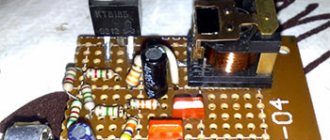
A supercapacitor instead of a battery - a practical overview of supercapacitor assembly
In practice, such a device is capable of operating many times longer than batteries of various types, of course, subject to operation in certain modes. This is the peculiarity of using an ionistor instead of a battery and its advantage:
But the ionistor used instead of a battery has not only such features; I will tell you about them after assembling the drive.
Ionistor instead of battery - battery assembly procedure
In this review, I will assemble an energy storage device using eight capacitors connected in a back-to-back circuit. In principle, there will be four organized pairs of two containers connected in parallel, and the pairs, in turn, are connected in series.
The enameled wire must be leveled and the varnish removed from it. This is done using a working knife or a special tool for stripping wires (whoever has one).
We form copper wire into connecting bars
It is necessary to make three square elements and a pair of poles for the “+” and “-“ terminals
We solder the nuts to the formed contact products to which the power wires will be connected.
Tin the junctions of the squares.
We connect the containers into a battery, solder the conductors to the terminals of the capacitor, while observing the polarity.
First you need to assemble four groups.
Now we solder the busbars to connect the power wires.
At this stage, you need to charge the battery with a current of 5A.
After five minutes the drive will be fully charged.
We do a test test with an incandescent lamp.
We make a short circuit of the output contacts - the wire warms up to a red state.
We test the battery by connecting an electric motor.
Where is this design used?
You can use an ionistor instead of a battery where there are large and cyclic current loads. A classic example: a storage tank for a subwoofer installed in a car. In addition, a supercapacitor can be used in devices where constant charge/discharge cycles occur, for example: devices for storing solar energy with its subsequent transfer to lighting lamps at night.
Variable capacitor: description, device and diagram
What is an element such as a capacitor? This is a small radio element with a concentrated electrical capacitance formed by two or more electrodes. In some cases, this element is also called the lining. These small parts are separated by a thing called a dielectric (special paper, a thin layer of mica, ceramic, etc.). The capacity of this part will depend on indicators such as the size (area) of the plates, the distance between these elements, as well as on the properties of the dielectric itself.
general information
A very important fact. A capacitor has one property that manifests itself in an alternating current circuit. For such a circuit, this part will be a resistance, the value of which will depend on the frequency. If the frequency increases, the resistance will decrease, and vice versa.
There are basic units of measurement with which you can determine the identity of a particular capacitor. These include Farad, microFarad, etc. The designation on the elements of these units, respectively, is: F, μF.
Marking
There are three main parameters that characterize a capacitor: the nominal capacity, tolerance and nominal voltage. In most cases, two marking methods are used - alphanumeric and numeric.
In the first case, the letter denotes the capacitance value (μ, nF, pF) and plays the role of a decimal point. For example, if a non-polar capacitor is marked 1 μ, then it is a part with a capacity of 1 μF, and the inscription 3μ3 means 3.3 μF.
A letter encoding can be used to indicate tolerance; its decoding is presented in Figure 8.
Figure 8. Decoding of letter marking of tolerance
The operating voltage of the capacitance can also be indicated by a letter code; its decoding is given below.
Table: explanation of the letter marking of permissible voltage
Small containers, for example, in SMD version, are usually marked with a three-digit digital code.
Three-digit digital code for capacity parameter
In order not to remember all the table values, use the following decoding rule: the values are given in picofarads, the first and second values are the mantissa, the third is a power with a base of 10. For example, the inscription 331 will mean 330 pF (33*10).
Variable Capacitance Cells
The dielectric in such elements is most often air. Although it is worth noting that, if we talk about equipment with small dimensions, for example, about transistor pocket receivers, then they often use variable capacitors with a solid dielectric. Wear-resistant and high-frequency raw materials are used as this element. Most often it is fluoroplastic or polyethylene.
Using an electrical double layer
For many decades, electrolytic capacitors had the highest capacity. In them, one of the plates was metal foil, the other was an electrolyte, and the insulation between the plates was metal oxide, which coated the foil. For electrolytic capacitors, the capacity can reach hundredths of a farad, which is not enough to fully replace the battery.
Large capacitance, measured in thousands of farads, can be obtained by capacitors based on the so-called electrical double layer. The principle of their operation is as follows. An electric double layer appears under certain conditions at the interface of substances in the solid and liquid phases. Two layers of ions are formed with charges of opposite signs, but of the same magnitude. If we simplify the situation very much, then a capacitor is formed, the “plates” of which are the indicated layers of ions, the distance between which is equal to several atoms.
Supercapacitors of various capacities produced by Maxwell
Capacitors based on this effect are sometimes called ionistors. In fact, this term not only refers to capacitors in which electrical charge is stored, but also to other devices for storing electricity - with partial conversion of electrical energy into chemical energy along with storing the electrical charge (hybrid ionistor), as well as for batteries based on double electrical layer (so-called pseudocapacitors). Therefore, the term “supercapacitors” is more appropriate. Sometimes the identical term “ultracapacitor” is used instead.
KPI parameters
The main parameter for such parts, which will help determine the ability of the device to operate in an oscillatory circuit, has become the minimum and maximum capacitance. This indicator is most often indicated next to the variable capacitor itself on the device diagram.
It is worth noting that in devices such as radio receivers and radio transmitters, several oscillatory circuits are used at once. In order to configure the operation of several parts at once, capacitor blocks are used. One block most often consists of two, three or more KPI sections.
The rotor part for such units is usually mounted on one common shaft for all variable capacitors. This is done for convenience, since when just one rotor rotates, it becomes possible to change the capacity of all devices located in this section at once.
Connection diagrams for an operating voltage of 380 V
Industrially produced asynchronous three-phase motors can be connected in two main ways:
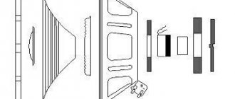
Electric motors are structurally made of a movable rotor and a housing into which a stationary stator is inserted (can be assembled directly in the housing or inserted there). The stator consists of 3 equal windings, wound in a special way and located on it.
In a star connection, the ends of all three motor windings are connected together, and three phases are supplied to their beginnings. When connecting windings in a triangle, the end of one is connected to the beginning of the next.
Triangle and star connection.
PDA design
In order to change or determine the capacitance of a variable capacitor of this type, it is necessary to rotate the rotor. If we talk about the simplest equipment, then it most often uses a wire tuning capacitor. This part consists of a piece of copper wire with a diameter of 1-2 mm. The length of this element is 15-20 mm. An insulated wire with a diameter of 0.2-0.3 mm is wound onto the wire very tightly, turn to turn. In order to change the capacitance in this device, it is necessary to unwind the wire. To prevent the winding from slipping off at this time, it is necessary to impregnate it with any insulating compound.
Accumulated energy
The amount of energy stored in a capacitor, expressed in joules:
E = CU 2 /2, where C is the capacitance, expressed in farads, U is the voltage on the plates, expressed in volts.
The amount of energy stored in the capacitor, expressed in kWh, is:
W = CU 2 /7200000
Hence, a capacitor with a capacity of 3000 F with a voltage between the plates of 2.5 V is capable of storing only 0.0026 kWh. How does this compare to, for example, a lithium-ion battery? If we take its output voltage to be independent of the degree of discharge and equal to 3.6 V, then an amount of energy of 0.0026 kWh will be stored in a lithium-ion battery with a capacity of 0.72 Ah. Alas, a very modest result.
Resistance capacitance of a capacitor in an alternating current circuit
It is important to note here that current in a circuit in which there is a capacitor can only flow if the applied voltage changes. You also need to understand that the strength of the current that will circulate in the circuit during the discharge and charge of this element will be greater, the greater the capacitance of the capacitor itself, and will also depend on the speed at which changes in the electromotive force (EMF) occur.
One more property. A capacitor with variable capacitance, which is connected to a circuit with alternating current, will be a resistance for this circuit. In other words, the value of the capacitance resistance will be the smaller, the greater the value of the capacitance itself and the higher the frequency of the operating current. However, this statement is true only for a circuit in which the current is alternating. The capacitance of the capacitor is equal to infinity, that is, its resistance will be infinite if such an element is placed in a circuit with direct current.
Design features of the ionistor
In essence, this is an ordinary capacitor with a large capacity. But ionistors have a high resistance, because the element is based on an electrolyte. This is the first. The second is the low charging voltage. The thing is that in this supercapacitor the plates are located very close to each other. This is precisely the reason for the reduced voltage, but it is precisely for this reason that the capacitance of the capacitor increases.
Factory ionizers are made from different materials. The covers are usually made of foil, which is separated by a dry substance with a separating effect. For example, activated carbon (for large plates), metal oxides, polymer substances that have high electrical conductivity.