Power supplies for radio and electrical equipment almost always use rectifiers designed to convert alternating current to direct current. This is due to the fact that almost all electronic circuits and many other devices must be powered from DC sources. A rectifier can be any element with a nonlinear current-voltage characteristic, in other words, passing current differently in opposite directions. In modern devices, planar semiconductor diodes are usually used as such elements.
Planar semiconductor diodes
Along with good conductors and insulators, there are many substances that occupy an intermediate position in conductivity between these two classes. Such substances are called semiconductors. The resistance of a pure semiconductor decreases with increasing temperature, unlike metals, whose resistance increases under these conditions.
By adding a small amount of impurity to a pure semiconductor, its conductivity can be significantly changed. There are two classes of such impurities:
Figure 1. Planar diode: a. diode device, b. designation of a diode in electrical circuits, c. appearance of planar diodes of various powers.
The layer at the interface of p- and n-type semiconductors (pn junction) has one-way conductivity? conducts current well in one (forward) direction and very poorly in the opposite (reverse) direction. The structure of a planar diode is shown in Figure 1a. The basis ? a semiconductor plate (germanium) with a small amount of donor impurity (n-type), on which a piece of indium, which is an acceptor impurity, is placed.
Once heated, indium diffuses into the adjacent regions of the semiconductor, converting them into a p-type semiconductor. A pn junction occurs at the boundary of regions with two types of conductivity. The terminal connected to the p-type semiconductor is called the anode of the resulting diode, the opposite? its cathode. An image of a semiconductor diode on circuit diagrams is shown in Fig. 1b, appearance of planar diodes of various powers? in Fig. 1st century
The simplest rectifier
Figure 2. Current characteristics in various circuits.
The current flowing in a conventional lighting network is variable. Its magnitude and direction change 50 times within one second. A graph of its voltage versus time is shown in Fig. 2a. Positive half-cycles are shown in red, ? negative.
Since the current value varies from zero to the maximum (amplitude) value, the concept of the effective value of current and voltage is introduced. For example, in a lighting network the effective voltage value is 220 V? in a heating device connected to this network, the same amount of heat is generated over equal periods of time as in the same device in a 220 V DC circuit.
But in fact, the network voltage changes in 0.02 s as follows:
- the first quarter of this time (period)? increases from 0 to 311 V,
- second quarter of the period? decreases from 311 V to 0,
- third quarter of the period? decreases from 0 to 311 V,
- last quarter of the period? increases from 311 V to 0.
In this case, 311 V? voltage amplitude Uо. The amplitude and effective (U) voltages are related to each other by the formula:
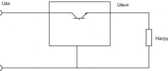
When a series-connected diode (VD) and load are connected to an alternating current circuit (Fig. 2b), current flows through it only during positive half-cycles (Fig. 2c). This happens due to the one-way conductivity of the diode. Is such a rectifier called half-wave? During one half of the period there is current in the circuit, during the second? absent.
The current flowing through the load in such a rectifier is not constant, but pulsating. You can turn it almost constant by connecting a filter capacitor Cf of a sufficiently large capacity in parallel with the load. During the first quarter of the period, the capacitor is charged to the amplitude value, and in the intervals between pulsations it is discharged to the load. The tension becomes almost constant. The greater the capacitor capacity, the stronger the smoothing effect.
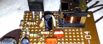
Charger protection circuit
The simplest protection system can be implemented using several radio elements. Relay with a contact current exceeding the charging current (for example 16 A) - a 5-9 V DC coil. Diode - 1 A, resistor R - 5 times greater than the resistance of the relay coil. Capacitor C - for example 220 uF 25 V. Of course, the circuit has a drawback - after disconnecting the battery, the relay continues to work until the power supply is turned off.
There are two solutions you can use. First install an additional rectifier diode in the opposite direction to the "zener diode" in the relay coil circuit. The second solution is to put a rectifier diode in the opposite direction instead of the "zener diode" and an LED in the opposite direction plus a resistor and use it as a sign for the reverse connection of the battery.
I also recommend using Schottky diodes, for example, from a computer power supply. These diodes generate less heat than conventional ones. Further reduction of power losses in the rectifier can be achieved by using a transformer with a symmetrical (double) secondary winding. The transformer here is 50 watts, you can't expect much from it, but it still does its job for a long time.
Diode bridge circuit
More advanced is the full-wave rectification circuit, when both positive and negative half-cycles are used. There are several varieties of such schemes, but the most commonly used is pavement. The diode bridge circuit is shown in Fig. 3c. The red line on it shows how current flows through the load during positive times, and the blue line? negative half-cycles.
Figure 4. 12 volt rectifier circuit using a diode bridge.
In both the first and second half of the period, the current through the load flows in the same direction (Fig. 3b). The amount of pulsation within one second is not 50, as with half-wave rectification, but 100. Accordingly, with the same filter capacitor capacity, the smoothing effect will be more pronounced.
As you can see, to build a diode bridge you need 4 diodes? VD1-VD4. Previously, diode bridges on circuit diagrams were depicted exactly as in Fig. 3c. The image shown in Fig. 1 is now generally accepted. 3g. Although there is only one picture of a diode, it should not be forgotten that the bridge consists of four diodes.
The bridge circuit is most often assembled from individual diodes, but sometimes monolithic diode assemblies are also used. They are easier to mount on the board, but if one arm of the bridge fails, the entire assembly is replaced. The diodes from which the bridge is mounted are selected based on the amount of current flowing through them and the amount of permissible reverse voltage. This data can be obtained from diode instructions or reference books.
The complete circuit of a 12 volt rectifier using a diode bridge is shown in Fig. 4. T1? step-down transformer, the secondary winding of which provides a voltage of 10-12 V. Fuse FU1? This is a useful detail from a safety point of view and should not be neglected. The brand of diodes VD1-VD4, as already mentioned, is determined by the amount of current that will be consumed from the rectifier. Capacitor C1? electrolytic, with a capacity of 1000.0 μF or higher for a voltage of at least 16 V.
Output voltage? fixed, its value depends on the load. The higher the current, the lower the voltage. To obtain a regulated and stable output voltage, a more complex circuit is required. Obtain the regulated voltage from the circuit shown in Fig. 4 can be done in two ways:
It is hoped that the descriptions and diagrams given above will provide practical assistance in assembling a simple rectifier for practical needs.
There is an inconsistency in electrical engineering. On the one hand, it is more convenient to transmit energy over long distances if it is in the form of alternating voltage. On the other hand, direct current is required to power smartphones, LEDs in light bulbs, circuit boards in TVs and similar household appliances. This problem is successfully solved by a family of radio components such as rectifier diodes.
Transformer
The transformer consists of a core made of a ferromagnetic material, as well as primary and secondary windings. 220 volts comes to the primary winding, and in this case, 12 are removed from the secondary winding, going to the rectifier. The cores in this type of power supply are mostly made in W- and U-shapes.
The arrangement of the windings is allowed either one on top of the other on a common coil, or separately. For example, a U-shaped core has a pair of coils, each of which has half of the windings wound on it. When connecting a transformer, the terminals are connected in series.
What are diodes
A diode is a semiconductor element based on a silicon crystal. Previously, these parts were also made of germanium, but over time this material was forced out due to its shortcomings. The electrical diode functions as a valve, i.e. it allows current to flow in one direction and blocks it in the other. Such capabilities are built into this part at the level of the atomic structure of its semiconductor crystals.
Read also: DIY Japanese rock garden: principles of arranging a stone garden at the dacha
One diode cannot obtain a full constant voltage from an alternating voltage. Therefore, in practice, more complex combinations of these elements are used. An assembly of 4 or 6 parts, combined according to a special circuit, forms a diode bridge. He is already quite capable of coping with full current rectification.
Interesting. Diodes have parasitic sensitivity to temperature and light. Transparent rectifiers in a glass case can be used as light sensors. Germanium diodes (approx. D9B) are suitable as a temperature-sensitive element. Actually, due to the strong dependence of the properties of these elements on temperature, they stopped producing them.
List of elements.
R1 = 2.2 kOhm 1W R2 = 82 Ohm 1/4W R3 = 220 Ohm 1/4W R4 = 4.7 kOhm 1/4W R5, R6, R13, R20, R21 = 10 kOhm 1/4W R7 = 0.47 Ohm 5W R8, R11 = 27 kOhm 1/4W R9, R19 = 2.2 kOhm 1/4W R10 = 270 kOhm 1/4W R12, R18 = 56 kOhm 1/4W R14 = 1.5 kOhm 1/4W R15, R16 = 1 kOhm 1/4W R17 = 33 Ohm 1/4W R22 = 3.9 kOhm 1/4W RV1 = 100K trimmer P1, P2 = 10KOhm linear potentiometer C1 = 3300 uF/50V electrolytic C2, C3 = 47uF/50V electrolytic C4 = 100nF polyester C5 = 200nF polyester C6 = 100pF ceramic C7 = 10uF/50V electrolytic C8 = 330pF ceramic C9 = 100pF ceramic D1, D2, D3, D4 = 1N5402,3,4 diode 2A - RAX GI837U D5, D6 = 1N4148 D7, D8 = 5.6V Zener D9, D10 = 1N4148 D11 = 1N4001 diode 1A Q1 = BC548, NPN transistor or BC547 Q2 = 2N2219 NPN transistor - (Replace with KT961A - everything works) Q3 = BC557, PNP transistor or BC327 Q4 = 2N3055 NPN power transistor ( replace with KT 827A ) U1, U2, U3 = TL081, op. amplifier D12 = LED diode
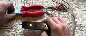
As a result, I assembled a laboratory power supply myself, but in practice I encountered something that I considered necessary to correct. Well, firstly, this is the power transistor Q4 = 2N3055 ; it must be urgently crossed out and forgotten. I don’t know about other devices, but it is not suitable for this regulated power supply. The fact is that this type of transistor fails instantly if there is a short circuit and the current of 3 amperes does not draw at all!!! I didn’t know what was wrong until I exchanged it for our native Soviet KT 827 A. After installing it on the radiator, I didn’t know any grief and never returned to this issue.
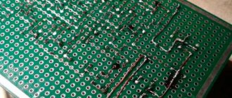
As for the rest of the circuitry and parts, there are no difficulties. With the exception of the transformer, we had to wind it. Well, this is purely out of greed, half a bucket of them is in the corner - don’t buy it =))
Well, in order not to break the good old tradition, I post the result of my work to the general court