LEDs have long been used in any technology due to their low consumption, compactness and high reliability as a visual display of system operation. An LED voltage indicator is a useful device needed by amateurs and professionals to work with electricity. The principle is used in the illumination of wall switches and switches in surge protectors, voltage indicators, and test screwdrivers. Such a device can be made with your own hands due to its relative primitiveness.
Purpose of elements and principle of operation of the circuit
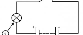
Many readers have LED light switches installed in their homes. The LED backlight circuit looks like this:
- A chain consisting of a quenching resistor, an LED and a simple silicon diode is switched on parallel to the switch contact.
- When the switch is open, electric current flows through a quenching (current-limiting) resistor, back-to-back LEDs and an incandescent lamp.
- During one of the half-waves, when a positive voltage is applied to the anode of the LED, the light-emitting diode glows. This not only provides illumination of the switch, but also provides LED voltage indication.
If we remove the switch, light bulb and wires from the circuit, we are left with a chain consisting of a resistor and two diodes. This chain is the simplest indicator (pointer) of 220 V alternating current.
Let us dwell in more detail on the purpose of the circuit elements. We indicated above that the operating current of the signal LED is about 10-15 mA. It is clear that when a light-emitting diode is directly connected to a 220 V network, a current will flow through it many times greater than the maximum permissible value. In order to limit the current of the LED, a quenching resistor is connected in series with it. You can calculate the resistor value using the formula:
R = (U max – U led) / I led
In it:
- U max – maximum measured voltage;
- U led – voltage drop across the LED;
- I led – operating current of the light-emitting diode.
Having performed the simplest calculation, for a 240 V network we get the value of resistor R1 equal to 15-18 kOhm. For a 380 V network, you need to use a resistor with a resistance of 27 kOhm.
The silicon diode performs the function of overvoltage protection. If it is missing, with a negative half-wave U, the locked LED will drop 220 V or 380 V. Most light-emitting diodes are not designed for such reverse voltage. Because of this, breakdown of the pn junction of the LED may occur. When a silicon diode is connected back-to-back, during the negative half-wave it will be open and U on the LED will not exceed 0.7 V. The LED will be reliably protected from high reverse voltage.
Based on the considered circuit, you can make a voltage indicator of 220/380 V. It is enough to supplement the radio elements with two probes and place them in a suitable housing. To make the indicator body, a large marker or thick felt-tip pen is suitable. You can place radio components on a homemade printed circuit board or make connections using a hinged method.
A hole is made in the marker into which an LED is inserted. A metal probe is attached to one end of the body. A wire is passed through the second end of the housing, going to the second probe or an insulated alligator clip.
Despite the simplicity of the design, the device will allow you to check the presence of voltage at the output of a circuit breaker or in a socket, and find a blown fuse in the distribution board. Note that the above indicator diagram is also used in industrial products.
Slowly changing color RGB LEDs and their application for display
Yes, yes, diaivaya, a very fashionable word on the Internet these days. DIY or made by hand our way. Life on Muska, I see, doesn’t calm down even in the New Year, so I decided to share my handjob too. Actually, I already mentioned these LEDs in my review of garlands, but I used them extremely successfully (as it seems to me), so it’s not a sin to write a separate review. The LEDs themselves, in fact, do not represent anything supernatural - ordinary-looking narrowly directed 5mm LEDs in a transparent housing. But inside there are actually three LEDs and a control chip that smoothly switches them, thus changing the color of the glow “across the rainbow”
video of how they work here:
Actually, this concludes the review of LEDs
After purchasing a 3D printer, I began to be interested in ready-made models for printing. Well, of course, the first thing I found was the site thingiverse.com. And on it, in particular, there is a wonderful night light “Magic Mushrooms - a lighted decoration”. Well, on the eve of the New Year, I decided to print a couple of pieces for gifts. Undoubtedly, this review would not have existed if I had not finished finishing off that model. More precisely, I printed several new parts and one to replace the used one - namely the back cover.
Unfortunately, in the original model the lid is made somehow stupidly and not only does it close awkwardly, but it also doesn’t hold well, moreover, there’s no way to put a holder for batteries in it. And so that it wouldn’t dangle or fall through, I printed a couple of 5x10x1mm plates that I glued with dichloroethane from the inside of the case so that the lid wouldn’t rotate. In addition, since my LEDs are highly directional, I printed caps for them from transparent plastic that diffuse the light.
These LEDs can be powered by 2 or 3 AA/AAA batteries. I actually checked both options - everything works, but at 2V it’s already difficult. But I don't think that these lights will be turned on so often and run for a long time that this will become a problem.
When developing the cover, I was guided by holders for 3 * AAA batteries purchased offline, and switches that came from China by mistake
My models are posted here: yadi.sk/d/KLTZkkDeN5xPpw
Well, actually, let’s start making a night light. Printing details:
The plates are already glued into the case, they are visible in the hole at the top and bottom. The lid rests on them; they prevent it from turning on the protrusions that are inserted into the grooves. The lid turned out funny, it’s called “surprised boy”
LED caps:
Regarding printing: don’t ask me about printer settings, I’m still completely green.
We glue the stems of the mushrooms to the stump with Chinese snot using a heat gun (I also wrote about the correct gun with a valve), it may be necessary to bore the holes and select the location so that the caps do not overlap too much in space. You can pre-fix it with a soldering iron.
Next we solder the wires to the LEDs. The thinner and softer the wires, the better. We observe the polarity so as not to get confused later. We leave the LED leads somewhere around 3-5mm; after soldering, we stretch heat shrink onto one.
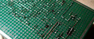
To connect all the wires into a pile inside the stump, I used a thin strip of 2-sided fiberglass. We solder the positives on one side, the negatives of the diodes on the other, then connect them to the battery via a switch. The switch, by the way, is attached to the lid by melting the pins.
Don’t pay attention to the batteries, for testing I plugged in something cheap from a fixed price.
Well, the result:
As you can see, the LEDs do not (and are not required to) work strictly synchronously, so after some time they become desynchronized, which is only beneficial. A nice feature is the fact that you don’t have to worry about the print quality of most of the details, because this only adds texture, which is very appropriate here. Theoretically, you can add a touch switch, a lithium battery and USB charging, but this is up to everyone to decide for themselves.
Personally, I'm more than pleased with the result. I recommend these LEDs for such crafts, and a 3D printer for such crafts
DC Voltage Check
Often there is a need to ring the low-voltage circuit of household appliances, or check the integrity of a connection, for example, a wire from headphones.
As a current limiter, you can use a low-power incandescent lamp or a 50-100 Ohm resistor. Depending on the polarity of the connection, the corresponding diode lights up. This option is suitable for circuits up to 12V. For higher voltages, you will need to increase the limiting resistor.
Selecting an indicator screwdriver
When purchasing an indicator screwdriver, it is recommended to select it according to the necessary parameters, based on the conditions under which it will be used.
It is important to know the voltage range. For operation in a single-phase network, the measurement interval lies in the range of 70-250 V or 100-250 V
In three-phase circuits, there are models that are capable of making changes at voltages up to 400 V. There are low-voltage models (12-24-36 V). The dimensions of screwdrivers come in two different variations: 12 cm and 18-19 cm. Small-sized tools are convenient to work in tight spaces; long ones, on the contrary, are convenient to reach hard-to-reach wires or contacts.
AC and DC voltage indicator up to 600 V
The next option is a slightly more complex system, due to the presence in the circuit, in addition to the elements already known to us, of two transistors and a capacitance. But the versatility of this indicator will pleasantly surprise you. It can safely check the presence of voltage from 5 to 600 V, both direct and alternating.
The main element of the voltage indicator circuit is a field-effect transistor (VT2). The threshold voltage value that will allow the indicator to operate is fixed by the gate-source potential difference, and the maximum possible voltage determines the drop at the drain-source. It functions as a current stabilizer. Feedback is provided through a bipolar transistor (VT1) to maintain the set value.
The operating principle of the LED indicator is as follows. When a potential difference is applied to the input, a current will arise in the circuit, the value of which is determined by the resistance (R2) and the voltage of the base-emitter junction of the bipolar transistor (VT1). In order for a weak LED to light up, a stabilization current of 100 μA is sufficient. To do this, the resistance (R2) should be 500-600 Ohms, if the base-emitter voltage is approximately 0.5 V. A capacitor (C) is required to be non-polar, with a capacity of 0.1 μF, it serves as protection for the LED from current surges.
We select a resistor (R1) with a value of 1 MOhm; it acts as a load for the bipolar transistor (VT1). The functions of the diode (VD) in the case of DC voltage indication are pole testing and protection. And to check the alternating voltage, it plays the role of a rectifier, cutting off the negative half-wave. Its reverse voltage must be at least 600 V. As for the LED (HL), choose a super-bright one so that its glow at minimal currents is noticeable.
How to do a test: necessary materials
You can check the car yourself or contact the nearest service center. You can do it yourself only with the help of a homemade control. There are two types: for home and car, they differ significantly from each other. If a 220 volt control is suitable for a home, then only 12V is suitable for a car.
These two types of homemade ones are assembled almost identically, with one difference - the light source. For home testing, a regular 220V lamp is suitable, and a car tester uses a low-power lamp. A diagram is also drawn up that will make it easier to assemble the intended device.
Materials for creating a test:
- Light bulbs. In one case, a regular lamp, in the other, an LED lamp.
- Copper wires for the house and acoustic wires for the car;
- Insulating tape;
- Probes.
For home control, you also need an electric cartridge, but the wires must be 50 cm long. To take measurements inside the car, you need wires of at least 2 m. For the body of the device, you can purchase a regular cigarette lighter, which can be found in any auto store, but the dipstick can be replaced with a regular self-tapping screw. This device is very easy to use.
Indicator for microcircuits - logic probe
Having learned how to create a simple electrician's probe with your own hands, you can also make a simple logic probe based on LED, which will help you find faults in digital devices.
Logic probes have been around since the early days of computing. With their help, specialists analyzed the logical levels at the inputs and outputs of digital microcircuits. The high level (voltage) at the output of the logic element is assigned the value of logical “one”, and the low level is assigned the value of logical “zero”. By comparing the levels at the input and output of a digital microcircuit, you can judge its serviceability.
What is better to choose
All devices have their pros and cons that must be taken into account when purchasing them. In addition, you need to understand why it will be needed - for example, if the control has proven itself well in three-phase circuits, then there is little point in making it for home use.
Oddly enough, if a person does not understand electrics, then it is better for him to buy a semi-professional device - at least a universal probe for 220-380V. Besides the fact that this is simply a reliable and necessary device, if you have to invite an electrician or ask friends to look at the wiring, it is better if you have a good device at hand.
How to make an electrician's tester with your own hands?
Some thrifty hobbyists can find many useful things in their “arsenal,” including an earphone (capsule) for the TK-67-NT telephone.
Another similar device, equipped with a metal membrane, inside which there is a pair of series-connected coils, is also suitable.
Based on such a part, a simple sound probe can be assembled.
First of all, you need to disassemble the telephone capsule and disconnect the coils from each other. This is necessary in order to free their conclusions. The elements are placed in the earphone under the sound membrane, near the coils. After assembling the electrical circuit, we will receive a completely working identifier with sound indication, which can be used, for example, to check the tracks of printed circuits for mutual bridging.
The base of such a probe is an electric generator with an inductive opposite relationship, the main parts of which are a telephone and a low-power transistor (preferably germanium). If you do not have such a transistor, then you can use another one with NPN conductivity, but in this case the polarity of the power supply should be changed. If you cannot turn on the generator, the terminals of one (any) coil must be swapped with each other.
You can increase the sound volume by choosing the frequency of the electric generator so that it is as close as possible to the resonant frequency of the earphone. To do this, the membrane and the core must be placed at an appropriate distance, changing the interval between them until the desired result is obtained. Now you know how to make a voltage indicator based on a telephone earphone.
The manufacture and use of a simple voltage probe is clearly shown in the video:
2.4. BuySell 2.0: the most popular indicator for binary options
Combined pointer indicator with Parabolic modification. It tracks the trend well on the M30 and H1 periods: as long as there is a horizontal line of dots of a certain color, you need to open (including options) only in one direction.
At short periods, like most indicators of this type, it gives many false signals. but on a timeframe above M30 it gives confident signals for options with an expiration time of 1 hour or more.
• A reliable signal for a CALL option is the appearance of a blue arrow located above the blue line.
• A confident signal for a PUT option is the appearance of a red arrow located below the red line.
• The discrepancy between the color of the arrows and the color of the line can also be used, but the accuracy of such a signal is much lower.
It is strictly not recommended to open options during periods of unstable volatility (news, opening/closing, statistics release, closing of regular options) - at this time almost all indicators do not work correctly.
Voltage indicator on two-color LED
Another popular indication scheme is one that uses a two-color LED to display the state of charge of the battery or to signal when a lamp is turned on or off in another room. This can be very convenient, for example, if the light switch in the basement is located before the stairs leading down (by the way, do not forget to read an interesting article on how to illuminate the stairs with LED strip).
Before you go down there, you turn on the light and the indicator lights up red, when off you see a green glow on the key. In this case, you don’t have to go into a dark room and feel for the switch there. When you leave the basement, you know by the color of the LED whether the light in the basement is on or not. At the same time, you monitor the health of the light bulb, because if it burns out, the red LED will not glow. Here is a diagram of a voltage indicator on a two-color LED.
Connection security
When connecting to 220V, it should be taken into account that the light switch usually opens the phase wire. Zero in this case is carried out common throughout the room. In addition, the electrical network often does not have a protective ground, so even on the neutral wire there is some voltage relative to the ground. You should also keep in mind that in some cases the ground wire is connected to radiators or water pipes. Therefore, when a person comes into simultaneous contact with the phase and the battery, especially during installation work in the bathroom, there is a risk of being exposed to voltage between the phase and the ground.
In this regard, when connecting to the network, it is better to disconnect both the zero and the phase using a batch machine in order to avoid electric shock when touching live wires of the network.
Option for car
A simple circuit for indicating the vehicle's on-board voltage and battery charge. The zener diode limits the battery current to 5V to power the logic chip.
Variable resistors allow you to set the voltage level to trigger the LEDs. It is better to carry out the setup from a network stabilized power source.
Online resistance calculator
The task becomes more complicated if you want to connect not one, but several diodes.
To facilitate independent calculations, we have prepared an online calculator for calculating the resistance of resistors. If you connect several LEDs, you will need to choose between parallel and serial connections between them. And these circuits require additional calculations for the power supply. You can easily find them on the Internet, but we recommend using our calculator.
You will need to know:
- Power supply voltage.
- Diode voltage characteristics.
- Characteristics of the diode current.
- Number of diodes.
You also need to choose a parallel or serial connection scheme. We recommend that you familiarize yourself with the differences between connections in the chapters that we have prepared below.
Life-threatening voltage detector, manufacturing
The device is made with three transistors, without a board for surface mounting.
Please note that the circuit uses transistors of different structures. There are no special requirements for them; almost any will do. An LED and a buzzer are used as signaling elements. The role of the antenna is played by a piece of wire 5 cm long.
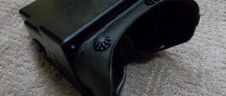
The detector is powered by two little finger elements. The body is a transparent plastic tube.
After assembly, if all elements of the circuit are in working order, the detector starts working immediately and does not need adjustment.
General recommendations for choosing a device for electrical wiring
Today, the choice of factory detectors is quite extensive, but some people often get “lost” in such a variety of devices. Therefore, before buying such a device, experts recommend clearly deciding what it is needed for - for single use or for constant work with hidden electrical wiring. Experienced craftsmen usually choose multifunctional devices that can recognize hidden metal elements of various characteristics.
Device for finding hidden electrical wiring for BOSCH brand professionals
When choosing a detector, you need to pay attention to the depth of its scanning. If the device is designed for a shallower depth, then during operation you can pass a wire located at a much greater distance from the wall surface being scanned. Professional detectors can operate over long distances
Typically, household devices are purchased for home use, which are quite suitable for the walls of apartments, private houses and thin partitions.
Professional detectors can operate over long distances. Usually, household devices are purchased for home use, which are quite suitable for the walls of apartments, private houses and thin partitions.
Budget options that allow you to find only live wiring are much inferior in efficiency to expensive models, but they will help save a person from burns during work.
Nuances in the operation of the voltage indicator
A self-assembled LED indicator, just like industrial devices of this type, can be used to check the presence of voltage. It is not a measuring device, but only indicates the presence or absence of voltage. Having gained some experience with the pointer, you can determine the voltage between two conductors by the brightness of the light-emitting diode. However, for accurate measurements you need to use pointer or digital voltmeters.
Unlike indicators with gas-discharge lamps, the LED indicator cannot be used to find the “phase” by touching one of the probes with your finger. The device has low internal resistance, and this method of searching for a phase conductor can result in electric shock.
Electricity from two rods
This method is based on a completely different theory and has nothing to do with the Earth’s magnetic or electric field. And this theory is about the interaction of galvanic pairs in a saline solution. If you take two rods of different metals and immerse them in such a solution (electrolyte), a potential difference will appear at the ends. Its value depends on many factors: composition, saturation and temperature of the electrolyte, size of the electrodes, immersion depth, and so on.
Such generation of electricity is also possible through the ground. We take 2 rods from different metals, forming a so-called galvanic pair: aluminum and copper. We immerse them in the ground to a depth of approximately half a meter, keeping the distance between the electrodes small, 20-30 cm is enough. We water the area of land between them generously with saline solution and after 5-10 minutes we take measurements with an electronic voltmeter. The meter readings may vary, but at best you will get 3V.
Note. The voltmeter readings depend on the soil moisture, its natural salt content, the size of the rods and the depth of their immersion.
In fact, everything is simple, the resulting free electricity is the result of the interaction of a galvanic couple, in which moist earth served as an electrolyte, the principle is similar to the operation of a salt battery. A real experiment on the potential difference across electrodes driven into the ground can be viewed at:
Important information about capacitors
Storage capacitors are used in a 220 V network:
- as a power supply (if the device is low-power);
- to coordinate loads;
- to smooth out tension;
- to smooth out the current.
Any of them consists of 2 conductive plates and a separating dielectric. The charge accumulates on the plates, but does not move between them. The shape can be cylindrical, flat, spherical. The dielectric is oiled paper, film, glass, mica, tantalum and aluminum oxides, and electrolytes.
Capacitors with protection class X2 are designed to operate at temperatures of -40-+110°C with a voltage of 250-310 V. Capacitance 0.001-2.2 µF, the main advantage is the ability to withstand increased loads caused by switching processes or lightning.