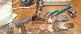
The problem of testing a newly installed local network is always relevant. Once upon a time I came across a piece of hardware called “Rapport II”, which, generally speaking, is a tester for CCTV systems, but it can also dial twisted pair cables. That piece of hardware died a long time ago, but the impression remains: when testing a twisted pair cable, it showed not just polarity reversal and uncoupling, but an exact crimping pattern! For example, for a crossover it looked like 1 → 3, 2 → 6, 3 → 1, and so on. But to pay about 800 non-Russian rubles for a device in which I will actually use only one function? Excuse me! How does it work, maybe it’s easier to do it yourself? Google in hand, and... complete disappointment. The search output consists of 80% of LED flashers on a shift register / AVR / PIC / your own version, and 20% of thoughtful discussions of forum gurus on the topic “buy %name_cool_hardware_for_100499.99_evergreen% and don’t worry.” Therefore, I want to offer the habra community my solution to this problem in DIY style. If anyone is interested, please see the cut below (be careful, there are a lot of photos!).
Multimeter backlight
A function that the multimeter lacks in poorly lit areas is display backlighting. Solving this problem is not difficult, just apply:
- 2 LEDs soldered in series to each other
- reflector - ordinary piece of gold from chewing gum
- microswitch of any type
Make a hole in the side of the housing for the switch. Glue the reflector under the indication display and solder two wires to the crown contacts.
They supply power to the switch and then to the LEDs. The structure is ready.
The final result of a homemade modification of the multimeter backlight will look like this:
The backlit battery will be used up much faster, so do not forget to turn off the switch when there is enough natural light.
Flashlight
The easiest way to test any type of battery is to insert it into a known-good device. Most often a flashlight.
It has a good current consumption and in the event of a battery failure, everything will immediately become clear.
The approximate degree of charge or discharge is determined by the intensity of the light bulb or LED. For accurate measurements you cannot do without a multimeter.
RF detector attachment for multimeter
The simplest circuit of an attachment to a digital multimeter for measuring RF alternating current. Suitable for measuring the power of an audio amplifier or radio transmitter. The multimeter must be supplemented with a simple remote measuring head containing a high-frequency detector using germanium diodes. This circuit rectifies and filters the alternating voltage signal, turning it into an easily measurable constant.
The input capacitance of the RF head is less than 3 pF, which allows it to be connected directly to the cascade circuit. You can use high-frequency Soviet diodes D9, GD507 or D18. The RF head is assembled in a shielded housing on which terminals are located for connecting the probe or conductors to the circuit being measured. Communication with the tester must be using a shielded TV cable.
Smartphone app
After the adapter is soldered, download the application from (active link to the application) and install it. Launch the application and connect the adapter. Everything should work. If you close the probes, you will hear a beep, which means everything is fine and you can use it. Initially zeros are shown:
And when you close the probes together, this word appears and the phone beeps.
Options for caps for probes
Replacement caps for probes can be purchased at any radio store. Separate caps for the tips of the multimeter contacts can be purchased at a radio store. Often these parts are lost, and storing the tool without them is unacceptable, since there is a high risk of breakage. You can use options from improvised means.
- We take a regular cap from a gel pen and pour hot glue inside.
- Be sure to lubricate the dipstick tip with oil or Vaseline.
- We insert the probe inside the product and wait until the adhesive base hardens.
- Carefully remove the tip and wipe off the grease.
Next, we make the second cap in the same way.
Connecting a multimeter to measure voltage should only be done if the instrument is fully operational. Otherwise, operation of the tester is considered unsafe.
Constructor for assembling a popular transistor tester
Today I will try to talk about one of the most popular homemade measuring instruments. Or rather, not only about the device itself, but about the designer for its assembly. I’ll say right away that it can be found cheaper in an already assembled form, but what will replace the interest in assembling the device with your own hands? In general, if anyone is interested, come in. It’s not for nothing that this device is considered one of the most popular multi-measuring devices. It deserves this due to its ease of assembly, great functionality and pretty good characteristics. It appeared quite a long time ago, it was invented by the German Markus Frejek, but somehow it so happened that at one stage he stopped developing this project and then another German, Karl-Heinz Kubbeler, took up it. Since it does not contain very many details, various radio amateurs and enthusiasts immediately began to repeat and refine it. About a year ago I posted a couple of options for repetition. The first had an addition in the form of autonomous power supply from a lithium battery and a charger for it. I modified the second one a little more, the main differences are that the encoder connection diagram has been slightly modified, the control of the boost converter for testing zener diodes has been redesigned, a software modification has been made, as a result of which when checking zener diodes you do not need to hold the button pressed, and the converter for the battery and charger At the time of publication, the second option was almost the maximum, the only thing missing was a graphical indicator.
Repair and operation
Repairing a soldering station assembled with your own hands comes down to replacing faulty elements. The sensor on the soldering iron most often fails. Operation in the correctly selected operating temperature range extends the service life of the tip and the quality of soldering work.
Soldering machines assembled by yourself work no worse than factory models. Minimum cost, little labor, and the installation will last a long time. Correctly selected circuit elements simplify the assembly and launch of the station.
Fitting and installation
To make the tester accurate, you need to adjust the resistor values. This part of the work is the most painstaking. Let's prepare the board for installation. To do this, you need to draw it into squares measuring a centimeter by a centimeter or a little smaller.
Then, using a shoemaker's knife or something similar, the copper coating is cut along the lines to the fiberglass base. The result was isolated contact pads. We noted where the elements would be located, and it looked like a wiring diagram right on the board. In the future, tester elements will be soldered to them.
In order for a homemade tester to give correct readings with a given error, all its components must have accuracy characteristics that are at least the same, or even higher.
We will consider the internal resistance of the coil in the magnetoelectric mechanism of the microammeter to be equal to 3000 Ohms stated in the passport. The number of turns in the coil, the diameter of the wire, and the electrical conductivity of the metal from which the wire is made are known. This means that the manufacturer’s data can be trusted.
But the voltages of 1.5 V batteries may differ slightly from those declared by the manufacturer, and knowledge of the exact voltage value will then be required to measure the resistance of resistors, cables and other loads with a tester.
Tester for testing in a housing, with sound
I have a tester, not the coolest, but it copes with its duties. But practice shows that 80 percent of the use of this tester is checking wires, coils, windings, diodes and transistors. Another 10 percent is determining the resistance of the resistors, and 10 percent is testing different voltages. And in order not to run the main tester for dialing, you can use a simple tester, which is designed for this.
If you have the same situation, then you can repeat the scheme, as it is very simple. This is a continuity tester for a break. They can easily check for broken wires, transformer windings, breakdowns of transistors and diodes, and anything else where a simple test or continuity test is needed.
Replacing the crown in a multimeter with a lithium-ion battery from a phone
In recent years, it has become very popular to remake a multimeter by replacing the power supply from the original crown with a lithium-ion battery from cell phones and smartphones. For these purposes, in addition to the battery itself, you will need charging and discharging boards. They are bought on Aliexpress or other online stores.
The overdischarge protection board for such batteries is initially built into the battery in its upper part. It is needed so that the battery does not discharge beyond the nominally permissible limits (approximately 3 Volts and below).
The charging board does not allow the battery to be recharged above 4.2 Volts (link to aliexpress).
In addition, you will need a board that increases the voltage from 4V to the required 9V (link to aliexpress).
The battery itself fits compactly on the back cover and does not interfere with its closure.
First, the output voltage on the boost module must be set to 9 Volts. Connect it with wires to a multimeter that has not yet been converted and use a screwdriver to unscrew the required value.
You will have to make a hole in the case for a micro or mini USB charging connector.
The boosting module itself is located in the place where the crown should be.
Be sure to ensure that the wiring from the module to the battery is of the required length. In the future, this will allow you to easily remove the cover and, having halved the body, carry out an internal inspection of the multimeter if necessary.
After placing all the parts inside, all that remains is to solder the wiring according to the diagram and fill everything with hot glue so that nothing moves when moving the device.
It is advisable to fill not only the body with hot glue, but also the contacts with the wires in order to extend their service life.
A significant drawback of such a multimeter on a lithium-ion battery is its operation, or rather not operation, at subzero temperatures.
Once your multimeter sits in the trunk of a car or in a bag in the winter for a long time, you will immediately remember the battery.
And you might think, was such a change useful? Ultimately, of course, you decide, based on the operating conditions of the device.
Software part
To write the program, I used the AVR Studio 4 environment, C language. Below I will describe the algorithm of work, but I will not show the code, and there are reasons for this.
First of all, it's kind of creepy (the picture of the horse vomiting rainbows). Secondly, since this is DIY, then it’s not a sin to write the implementation of the algorithms described below yourself - otherwise, what kind of DIY is this? Well, thirdly, if you don’t want to write, then compiled .hex is present in applications. I don’t see any point in describing standard procedures such as working with an ADC, implementing exchange with an HD44780-compatible display, and similar obvious things. Everything was said long ago before me.
The tester's work is divided into several stages, which are repeated cyclically.
Stage 1: Initial checks
- Let's check if any active equipment is connected to the line. We transfer all control lines (port C, let me remind you) to the Hi-Z state, measure the voltage on all lines. They should be near zero. Otherwise, we understand that anything is connected on the other side of the wire, but not our counterpart, and there is no point in continuing further. But it makes sense to inform the user that “there is voltage on the line!”
- Let's check the signal level on PB2. If there is 0, then the battery is discharged. We will report the problem to the user, if everything is OK, move on.
Stage 2. Checking the integrity of the lines and the presence of short circuits
For each of the 8 lines we do the following. We supply +5V to it from port C, keeping all other lines of the port in a high-impedance state, and measure the voltage on the remaining lines. If all lines have near-zero values, the line under study is broken. If +5V also appears on one of the lines, this is a short circuit. Normally, we will see some intermediate values.
Stage 3. Determining the cross-connection scheme
Now we get to the most interesting part.
Having weeded out all obviously faulty lines (broken and shorted wires), we proceed to measuring the resistance of the remaining lines (let their number be N, 0 <= N <= 8). Let's introduce the notation: Rxy is the resistance between lines x and y. Rx is the value of the resistance connected to line x. It is clear that Rxy = Rx + Ry By measuring the resistance between the lines, we obtain a system of linear equations. By comparing the obtained values of R1... RN with the reference ones, we will find out the cross-connection scheme.
Resistance is easy to calculate. Let's apply a high level to line X, a low level to line Y, and leave the other lines of port C in Hi-Z. In the circuit (see Fig. 3), the voltage drop across the known resistance formed by the parallel connection of R1.Y and R2.Y according to the circuit is U1, and at the unknown Rxy it drops (U2 - U1). This means Rxy = (R1 || R2) * (U2 - U1) / U1. Rice. 3. Resistance measurement principle
If N < 3, we are powerless. We can make only one measurement of the resistance between them, while we have 2 unknowns - the resistance connected to each of them. A system in which the number of equations is less than the number of unknowns has an infinite number of solutions. The user will have to show the question marks on these lines - they seem to be working, but it is not possible to figure out the cross-connection scheme.
When N = 3 we have only one possible option. By measuring all available resistances R12, R13, R23, we get the system: R1 + R2 = R12 R1 + R3 = R13 R2 + R3 = R23 It is easy to show that: R1 = 1/2 * (R12+ R13 - R23) R2 = R12 - R1 R3 = R13 - R1.
When b o
At higher values of N, we can compose a system of equations in many ways, taking measurements of various resistances Rxy. At first glance, there is no difference in how to choose which resistances to measure. However, the devil is in the details. Using the example of N = 8, I will explain what I mean. In the first implementation of the algorithm, I made measurements like this: R1 + R2 = R12 R1 + R3 = R13 ... R1 + R8 = R18 R2 + R3 = R23 Adding the first two equations and subtracting the last, we get the same thing 2R1 = R12 + R13 - R23, and we will find all other resistances from equations 1 - 7, where R1 is already known.
The problem lies in the fact that with some types of cross-connection, the value of R1 turned out to be large (15 kOhm and above), and the error in measuring resistance increases with its increase. As a result, it turned out that small resistances relative to R1 with a nominal value of 1-2 kOhm were measured with an error of 70-80%! Obviously, to ensure good accuracy, we should compose the system so that in place of R1 there is another unknown, the smallest of all. To do this, we will have to perform all possible measurements (it’s good that there are not many of them, in the worst case 28). In fact, we got an 8 x 8 matrix, symmetrical about the main diagonal (clearly, Rxy = Ryx). Let us choose the minimum one from all the results, let it be Rij = Ri + Rj. In line i we find Rik, such that Rik > Rij, but less than other elements of the line. We get: Ri + Rj = Rij Ri + Rk = Rik Rj + Rk = Rjk We solve and find the smallest among Ri, Rj, Rk (let’s assume it turned out to be Ri). the remaining unknowns Rx are found from Rx = Rix - Ri.
Stage 4. Determining the break point, if any
Smart and expensive hardware measures the distance to the break point using TDR.
Difficult, expensive, cool. Our capabilities are much more modest, and it’s not very often that we need to know the position of a cliff down to centimeters - usually an understanding in the style of “right next to me”, “at the other end”, “in the middle where the wall was recently hollowed out” is more than enough. So - measuring the cable capacitance. We convert all lines of port C, except the one connected in the core where there is a break, to Hi-Z. We apply +5V to the core, charging it. Let's measure the voltage on it, this will be our initial U0. Convert all lines to Hi-Z. The cable discharge begins through resistor R2.X with a resistance of 1 MOhm. After waiting 1 ms, we measure the voltage on this line U.
We must not forget that the circuits on the board, connector, etc. also have their own capacity, so the device needs to be calibrated on a couple of pieces of cable of different lengths. I got 1710 pF at zero length, and the cable capacitance was 35 pF / m. Practice has shown that even if it lies, it’s not much, by 10 percent. A situation like “where did you miss the contact, in the closet on the patch panel or in the socket? solved instantly.
Types of probes
Universal probes Probes, like conductors, are one of the main parts of a measuring device. With their help, it is possible to accurately determine the contact, analyze the presence of voltage and leakage. They are always included. There are several types of structures.
Universal
These devices contain PVC conductors, which tend to crack in hot weather. The tips themselves are made of stainless steel. They come with a set of additional attachments. Experienced electricians believe that these parts are unreliable because they quickly lose contact with the conductor.
Branded
The probes have wires with improved flexibility. The tips have excellent sealing, the handles are rubberized, so they are comfortable to work with. Such parts are provided with special caps that provide protection from dust and moisture.
For SMD mounting
Probe-tweezers for checking SMD components Devices are convenient to connect. They are used for periodic measurements during SMD type installation. The tips are needle-shaped and equipped with protective caps. Using probes, you can pierce the cable insulation, as well as clean the solder mask on boards and other surfaces.
"Crocodiles"
Also considered convenient for electrical work. They are much more effective than sharp electrodes and can prevent short circuits during operation. The sizes of these probes usually vary. The parts must be in a dielectric shell.
Purpose and types of wires for a multimeter
Inexpensive multimeters are equipped with appropriate probes. The conductors that lead to the probes play a big role in the correct testing of any electrical appliance. However, if contact is broken, the device is not able to accurately measure the existing voltage and determine the performance of a particular device.
Usually this part comes with a multimeter, but it is better to have a supply of conductors in case the main ones are broken. Most of them have PVC insulation, which begins to crack with prolonged use. Often these parts are universal, so they fit most meter models.
Conductors can be hard (rubber-sheathed) or elastic (silicone-coated). The latter option is considered the most practical, as it can easily be twisted and any other type of deformation. Such parts are considered reliable and are easy to use even during work in any conditions.
Rigidly insulated conductors are more suitable for performing voltage testing in places where there is little free space. Rubberized parts are considered safe because they do not allow electricity to pass through. Suitable for the event that a breakdown has occurred in the electrical appliance being tested.
Even if the multimeter is equipped with new leads and probes, it is necessary to take into account safety precautions - wear rubber gloves while working.
Measuring instruments
To check the performance of the battery, several devices are used and a number of simple manipulations are performed:
- A multimeter is an affordable and convenient device that allows you to determine the condition of the battery with acceptable accuracy.
- A load fork is a device that allows you to simulate the starting load on the battery when starting the engine and at the same time measure the voltage drop at the battery terminals.
- A hydrometer is used to check the density of electrolyte in battery banks.
- A specialized window on the battery case is a color indicator of the charging status of maintenance-free and low-maintenance batteries. Green color indicates 100% charge, white indicates low electrolyte level, and black indicates the need to charge.
Determining the exact battery voltage
In order to find out the actual battery voltage yourself, you will need at least one accurate resistor with a nominal value of 2 or 2.2 kOhm with an error of 0.5%. This resistor value was chosen due to the fact that when a microammeter is connected in series with it, the total resistance of the circuit will be 5000 Ohms. Consequently, the current passing through the tester will be about 300 μA, and the needle will deflect to full scale.
I=U/R=1.5/(3000+2000)=0.0003 A.
If the tester shows, for example, 290 µA, then the battery voltage is
U=I*R=0.00029(3000+2000)=1.45 V.
Now knowing the exact voltage on the batteries, having one exact resistance and a microammeter, you can select the required resistance values of the shunts and additional resistors.
Hardware
Operating principle: the response part is a set of resistances of various values. Let's measure them. Knowing their ratings and the wiring of the mating part, we can find out exactly how the cable is crossed. Below is a diagram of the device (all illustrations are clickable). Specific resistance values were chosen based on availability in the store rather than deliberately, although a piece of the Fibonacci series was obtained.
Rice. 1. Tester circuit
Rice.
2. Scheme of the response part The heart of the circuit is the ATMega16 microcontroller. Why him? The “AVR vs PIC” debate is a typical holivar, so I’ll simply say: let AVR be my arbitrariness. And of their entire line, Mega16 is the cheapest crystal, having an on-board ADC for 8 channels. I frankly didn’t want to complicate the circuit with analog signal switches. An important plus: this model can be bought even in my castle, where there is one electronic components store in the whole city with prices at 150-500% of Moscow.
Port A of the microcontroller is the ADC inputs, on port B we have an ISP and a couple of service functions, port C is used to generate test signals, and port D is for communicating with the user via an HD44780-compatible display.
We power the circuit from a Krona battery, through a stabilizer LP2950, DA1 according to the circuit. Why not PWM, but a regular linear stabilizer, albeit a low-dropout one? The current consumption is small, I carried out all the testing and debugging of the circuit on one battery, I already launched a couple of real objects with fifty ports each - until it ran out. But high-frequency interference, which is a companion to any PWM, can reduce the accuracy of the ADC. Again, I don’t want to complicate the scheme. Why LP2950? He was in the store.
We will protect the input circuits using suppressors VD1.1 - VD1.8, I took 1.5KE6.8CA. Of course, they won’t save you from getting into 220V, but they can quite easily extinguish 60V from some telephone line.
The VD2 - R4 chain is used to detect low battery. The zener diode drops 5.1V. Thus, when the battery voltage drops below 6V, a log will appear on PB2. 0. A Schmitt trigger would have been needed here, but there was none.
We display information using an HD44780-compatible display; I came across WH-1604A-YYH-CT#. The connection diagram is typical and does not require any explanation. It is worth mentioning only the resistance value R5, which sets the brightness of the backlight. The higher the rating, the longer the battery will live - the rest of the circuit consumes less than 5 mA, the main consumer is the display backlight. But if you overdo it, you won't be able to see anything on the screen in the dark. I settled on 100 ohms.