High voltage generator from a transistor liner
Hello, dear friends!
Today I suggest you assemble a high-voltage generator using just one transistor from a TVS-110PTs15 line transformer with an UN9/57-13 voltage multiplier from an old color TV. The circuit is quite simple, built on the principle of blocking a generator and contains a small number of parts. Circuit of a high voltage generator from a liner on one transistor
To assemble the generator, you will need one KT819G transistor, or an imported analog TIP41C, but it is best to use MJE13009, since this transistor can withstand current up to 12 A and, accordingly, will heat up less. Personally, I used MJE13009 in my generator. Be sure to coat the transistor with thermal paste and install it on a radiator, preferably with a fan.
You will also need two 5-watt resistors. At 100 ohms and 240 ohms, the resistors in my generator got very hot and I decided to glue a small radiator with “poxy-pol”. The most important part of the generator is the TVS-110PTs15 line transformer; it is possible to use TVS-90LTs5 and other similar ones from old color, black-and-white and even tube TVs.
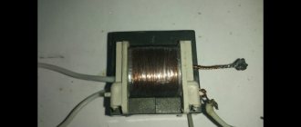
Linear transformer TVS-110PTs15
A couple of additional windings need to be wound on the magnetic core of the transformer. Coil L1 contains 10 turns, wound with wire with a diameter of 1 millimeter. We wind coil L2 with 1.5 millimeter wire, 4 turns in total. Both coils should be wound in the same direction. The secondary high-voltage winding remains unchanged.
Line transformer TVS-110PTs15 with two additional windings
The voltage multiplier UN9/27-13 or similar also needs minor modification. It is necessary to remove two unused terminals on it, marked in the picture with red arrows, then isolate these places with “poxy-pol”. It’s not necessary to do this, but if you accidentally touch these conclusions during the experiment... Your hair will stand on end and it won’t seem like much, of course it won’t kill you with an electric shock, there are very few amperes there, but it can burn you. A 470 ohm resistor is installed between the line transformer and the multiplier.
Voltage multiplier UN9/27-13
The arrester is made of two wires with a diameter of 1 millimeter. The distance between the electrodes is selected individually. To power the generator, it is best to use a power source from 12 to 30 volts with a current of at least 2A.
High voltage generator. Arrester
After power is applied, a powerful arc appears at the spark gap. How to measure the voltage at the output of a multiplier without a kilovolt meter? It is generally accepted that 1 millimeter of arc is 1 kilovolt, the length of the arc is 15 millimeters, which means the voltage at the spark gap is approximately 15 kilovolts.
I would like to say a few words about safety precautions. A high voltage of several tens of kilovolts is supplied to the spark gap from the multiplier, so do not touch the spark gap with your hands to avoid electric shock; even after turning off the power, high voltage remains in the multiplier capacitors. Of course, it won’t kill you with an electric shock, because there are not enough amperes, but it will hurt and possibly leave burns on the skin.
Friends, I wish you good luck and good mood! See you in new articles!
I recommend watching a video about how a high voltage generator works.
Arrester for 20..30 kV
The assembly sequence is shown below. It is practically no different from what was made for the spark gap from a bottleneck. Only the sizes of all the parts are larger.
Then all that remains is to assemble the arrester.
The spark gap works well with a spark length of up to 10 mm (in a housing made of 40 mm pipe) and up to 15 mm (in a housing made of 50 mm pipe), which corresponds to voltages above 30 kV.
With discharge energies of up to 10 J, the discharger lasts for several thousand pulses, after which it must be opened and the inside of the housing cleaned.
With a discharge energy of 120 J, the discharger lasts for several tens of pulses (closer to a hundred), after which it needs to be cleaned.
How to make an electrical erosion machine for your home workshop with your own hands?
Some home craftsmen have the idea of making an electrical erosion machine with their own hands for their own workshop. The desire is explained by the fact that sometimes it is necessary to process parts with high hardness. Annealing to reduce strength is not allowed. Deformation of the part is possible and the requirements for the quality of the processed surface or other characteristics will be violated.
As a result of spark erosion, through holes are burned or markings are applied. It is possible to process a surface of complex shape specified by the electrode.
Main features of electrical erosion
The operating principle of an erosion installation for metal parts is based on the removal of the smallest particles of the material being processed by a spark discharge. As a result of a single exposure, a small hole remains at the point of contact. The more powerful the spark, the wider and deeper the depression is formed.
Spark generator circuit:
The electrical circuit of the device provides for the use of:
- diode bridge, it rectifies the supplied alternating voltage from the 220 V network;
- a 100 W H₁ incandescent lamp represents a resistive load;
- capacitors C₁, C₂, C₃ accumulate energy to produce a one-time spark discharge.
When the circuit is connected to the network, the H₁ lamp lights up, and an electric charge accumulates on the capacitors C₁,..., C₃. When the capacitors are fully charged, the flow of electric current through the circuit stops. The H₁ lamp goes out, which serves as a signal for the possibility of a spark.
The electrode is applied to the part. There remains a gap through which breakdown occurs. A small hole is burned into the metal.
Similar actions happen many times. With each subsequent action, the electrode penetrates deeper into the metal, tearing out particles at a greater depth.
The above circuit requires about 0.5...0.7 s of time to fully charge the capacitors. The current value in the charge circuit is approximately 0.42...0.47 A. When contact is made in the discharge zone, the current increases to 7000...9000 A. At such a high value, 0.010...0.012 g of metal (steel) evaporates.
Communities › Do It Yourself › Blog › Homemade tester for checking ignition coils.
Greetings to all. There is an urgent need to check the ignition coils on a car. I know that there are such ready-made devices, but I don’t have the time or desire to look for them. Everything was done in half an hour and from scrap materials, costs accordingly = 0. We connect it to the coil, connect it to ground and start the car. Little by little we begin to unscrew the handle. The spark should be consistently strong even with a gap of 1-2 cm unscrewed. It is advisable to increase the speed. If the spark is strong and does not disappear, the coil is working. If the spark is thin or disappears altogether at a gap of 1 cm, then the coil is dead and will soon fail altogether. Hello everyone! You can see how it works
Technical specifications for the design of a homemade machine
To make a homemade electrical discharge machine, you need to make a number of devices that will help automate the production process.
- A frame is needed; the mechanism for moving the electrode will be placed on it.
- You will need a mechanism that allows you to periodically bring and remove the electrode to the material being processed.
- To burn holes of different shapes you need to have a set of electrodes. Experts recommend using molybdenum wire.
- For different types of main tools, you will need to change the device power and amperage. Under different operating modes, the electrical circuit diagram must allow regulation of the discharge value on the electrode. It is necessary to provide for a change in the voltage ripple frequency.
- To cool the part (hardened steel cannot be overheated; tempering occurs with a decrease in hardness), coolant must be supplied to the work area. More often, ordinary water or salt solutions are used. The water simultaneously washes away sludge (destroyed metal particles).
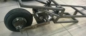
Development of a horizontal electrical discharge machine
The installation diagram includes the main components and parts:
- 1 – electrode;
- 2 – screw for fixing the electrode in the guide sleeve;
- 3 – terminal for fixing the positive wire from the voltage converter;
- 4 – guide sleeve;
- 5 – fluoroplastic body;
- 6 – hole for lubricant supply;
- 7 – bed.
The unit is small in size and can be placed on a table. In the housing 5, the guide sleeve 4 can move in both directions. To drive it you need a special mechanism or device.
Electrode 1 is attached to sleeve 4, the positive wire is also connected using terminal 3. All that remains is to assemble the proposed circuit into a real installation at home. It uses the simplest equipment.
Spark gap 10..12 kV
The plastic case is attached to the aluminum plane by gluing. At first this was done using epoxy and the result was unstable. Later it turned out that it is more convenient and reliable to glue with hot-melt adhesive (“glyugan”). For gluing, drill many holes with a diameter of 2 mm around the perimeter of the future adhesive seam. During the gluing process, the hot-melt adhesive will flow into them and form columns on which, like rivets, the entire structure will be securely held.
Cut the neck of a plastic bottle, straighten the cut, and glue it to the aluminum corner. Before gluing, it is advisable to heat the corner (flat electrode) to sixty degrees (hot to the touch). A sticker without additional heating gives less strength, which will reduce the maximum pressure (transmitted energy) withstand by the arrester.
Brief description of a homemade installation
Electrode 1 is installed in housing 2. Its reciprocating movement is carried out by an electromagnet from coil 7. Terminal 3 is connected to the guide sleeve (positive potential is applied).
The part to be processed is mounted on the work table 4. There is terminal 5 on the table; the negative conductor is connected to it. Lubricant is supplied through tube 6 into the housing.
By turning on the converter, operating voltage will be obtained on the current-carrying wires. Additionally, voltage is applied to the induction coil 7. It creates vibration of the electrode 1, directing its movement to the right and left. Electrode 1 touches the workpiece. A current of 7000...9000 A appears in the contact zone.
Each time the tool moves towards the part, a small amount of metal is burned off. Within 10...12 minutes of operation of the electrical erosive machine, a through hole will be obtained in the part. A hole is obtained in the drill shank. It is quite difficult to drill such a hole using the usual method.
Rail arrester
As promised, here is a guide to assembling a homemade adjustable double-gap rail arrester. To assemble it you will need: a pair of chrome-plated cylindrical door handles, a suitable piece (pieces) of aluminum corner, an aluminum rod (or copper or bronze) with a diameter of about 10 mm (a tube will also work, by the way, but you will have to slightly change the method of fastening). You will also need some plastic for the body, a couple of bolts and nuts and various kinds of plumbing tools.
All conductors (door handles, rod and corners) in the arrester should be as straight as possible. The arrester will not work correctly with bent parts. Instead of an aluminum corner, corner plinths are used here. Crisis of resources, what can you take. Let's hope you have better luck.
Cut the aluminum corner to the size of the used door handles with a small margin (for the walls of the case). Round the corners of the corner and handles.
Install door handle electrodes on the corners.
Make the bottom. Cut a rectangular piece of plastic, the length of the corner and the width calculated by the formula:
The door handles I used have a height of 16.3 mm (with a diameter of the cylindrical part of 11 mm), the diameter of the copper rod used is 10 mm. And since you want this arrester to have a full gap, varying within 3..6 mm (each of the gaps is one and a half millimeters), you need to take the width of the bottom equal to w = 16.3*2+2*1.5+10 = 45.6 mm. It will take some effort to cut the bottom more or less exactly to size and to ensure that it has straight sides and a rectangular shape. But it's worth it.
How to improve the machine?
The simplest machine made is a working model. Its purpose is to create holes in hardened parts.
In the future, you need to consider the option with a vertical electrode arrangement. Then you can install a bath underneath it. The process will occur without possible malfunctions associated with the presence of sludge that cannot be removed from the working area.
It is also necessary to consider additional mechanisms for smooth tool feeding. It may be necessary to carry out not only axial movement, but also movement of the electrode in the horizontal plane in order to carry out three-dimensional surface treatment.
Any simple machine gives ideas on how to further improve it and create a more convenient unit. The main thing is to take the first step and try to make the first sample.
Video: homemade electric spark machine.
DIY spark generator
Many of us have at least once in our lives seen photographs of High-Voltage Generators on the Internet or in real life, or taken them ourselves. Many circuits presented on the Internet are quite powerful, their output voltage ranges from 50 to 100 Kilovolts. The power, like the voltage, is also quite high. But their nutrition is the main problem. The voltage source must be of a power suitable for the generator and must be able to deliver a large current for a long time.
There are 2 options for powering high-voltage generators:
- battery,
- mains power supply.
The first option allows you to run the device far from the outlet. However, as previously noted, the device will consume a lot of power and, therefore, the battery must provide this power (if you want the generator to work “at 100”). Batteries of such power are quite large and a device with such a battery cannot be called autonomous. If the power is supplied from a network source, then there is no need to talk about autonomy either, since the generator literally “cannot be taken away from the outlet.”
My device is quite autonomous, since it does not consume much from the built-in battery, but due to low consumption, the power is also not great - about 10-15W. But you can get an arc from a transformer, the voltage is about 1 Kilovolt. From the voltage multiplier to higher - 10-15 kV.
Closer to the design...
Since I did not plan this generator for serious purposes, I placed all its “insides” in a cardboard box (no matter how funny it may sound, it is true. I ask you not to judge my design strictly, since I am not an expert in high-voltage technology). My device has 2 Li-ion batteries with a capacity of 2200 mAh. They are charged using an 8-volt linear regulator: L7808. It is also located in the case. There are also two chargers: from the mains (12 V, 1250 mAh) and from the car’s cigarette lighter.
Spark gap. A handy assistant in diagnosing the ignition system. Your own diagnostician!
Hello dear friends!
Having written an article about ignition diagnostics, I received more than one message about what is a spark gap?
For those who don’t know about such a good thing, I decided to write an article. I’ll tell you what a spark gap is, how to use it and how to use it to identify a malfunction of a coil, ignition module or high-voltage wire. If the topic is interesting, I will write a few more articles about available tools for self-diagnosis. There are many options for spark gaps. In order not to take photos from the Internet, I decided specifically for this article to order one of the cheapest arrester options, which is available to everyone, costs 300 rubles. In order not to advertise, I will not say where I got it specifically. I will say this: I ordered it from one of the famous Chinese sites. You can order it anywhere and whatever you want! And I’ll say more, you can do it yourself.
I will speak in simple words that everyone can understand. The spark gap is a device with contacts and a wire for connecting to ground. The distance between the contacts is adjustable and this is its main purpose. It allows you to set the gap between the contacts from 2-3 mm, simulating a standard factory spark plug. And also increase the gap to 20-30 mm, simulating the operation of the high-voltage part under load.
If we set the minimum gap between the contacts to 2-3 mm, then this will be a common imitation of a factory spark plug. You can use the old way to test the spark, take a spark plug and test the spark, but you need a spark gap to test under load. Moreover, it’s easier to use a spark gap, plug it into a wire or coil, wire to ground and that’s it, you don’t have to constantly keep the spark plug on ground.
But if we increase the gap from 20 to 30 mm, then we can check the high-voltage part (coil, module, high voltage wire under load).
If you have read my article on diagnosing the ignition system, then you know that there are two options. The first is when the engine runs well at idle or low load, but “troubles” when the speed increases sharply or the load increases. The second is when the engine always “troubles”, even at idle or under load. In the second case, everything is simple, if the engine constantly stalls (due to problems with the explosive part), then you need to connect a spark gap to a wire or coil on each cylinder and see where there is no spark. To do this, just set a gap of 10-15 mm and everything will become clear.
Connection is simple. We put a high-voltage wire or an individual ignition coil on the contact simulating a spark plug, start the engine and watch for a spark.
But with the first option it is more difficult. When the engine runs perfectly at idle or low load, the problem is not permanent and difficult to identify without diagnostic equipment or replacement parts. If misfires appear (engine misfires) during sudden acceleration or under heavy load, it means there is a high-voltage breakdown in the coil or high-voltage wire, a break or high resistance in the high-voltage wire, etc. This is where the spark gap will help you. We connect the arrester and set the distance between the contacts to 20-25 mm, if necessary 30 mm and see. As soon as you connect the problematic high-voltage wire or coil, there will be no spark at the spark gap. Why is that? The fact is that when you increase the distance between the contacts, you simulate the load. Under load on the spark gap or in the engine, the spark will go where it is easier for it and the path is shorter; if there is a malfunction (high-voltage breakdown, for example, in the coil body or its insulation), then there will be no spark between the contacts of the spark gap, as well as at the contacts of the spark plug. Because of this, misfires occur during sudden acceleration and load.
There is no need to “torture” the motor for a long time when the spark gap is installed; there is a large contact gap, more than 8 mm. Also, you should not drive a car with a faulty high-voltage part (breakdown, high wire resistance or breakage). This can damage the power transistors (switches) that control the coil.
Why did I call the spark gap an improvised tool? It is cheap and takes up very little space. You can take it with you or store it in the garage with all your tools. It will help you or your friends save money and time when troubleshooting!
Thank you all for your attention, if the article was useful to you, then I am very glad!
I would like to point out that I created
a group chat for car repair and troubleshooting. If you have any question, then write, I will try to help, or maybe another chat participant will help you.
All the best to you and good luck on the roads!!
Source
DIY electric spark machine
To change the shape and size of a metal workpiece, you can use the electrical discharge processing method. It has been used for many years in various industries, characterized by high accuracy but low productivity. To apply this processing method, you should use a special electric spark machine, which you can purchase or make yourself. The homemade version can be used in everyday life in small-scale production. The cost of making it yourself will be lower than purchasing an industrial version. Therefore, let’s take a closer look at how you can make the electric spark machine in question with your own hands, what you need for this and in what cases it can be used.
RADIO PARTS FOR ELECTRIC SHOCKER
Good afternoon friends. Many radio amateurs in personal messages are interested in where I find parts for stun guns. Today I will explain this to you in detail. Firstly, a high-voltage unit for the car’s xenon headlights.
Recently I specifically found several such blocks and now I want to tell you what kind of block we need. There are simply no unnecessary parts, since the device itself is a kind of stun gun with an output voltage of 25 kilovolts.
In it you can find low-frequency transistors of the IRFZ44 type, a spark (vacuum) gap, high-voltage capacitors with a larger capacity, capacitors for a multiplying stun gun, high-voltage diodes, a high-voltage transformer, a transformer for the shocker converter.
And I would like to draw your attention to the fact that all radio components here, including high-voltage transformers, are made at a high level and with excellent quality.
I carried out tests with a high-voltage transformer from such a block - I applied voltage to the primary winding from a capacitor with a capacity of 1 microfarad and a voltage of 1500 volts, but to my surprise, the spark from the secondary winding reached 7 centimeters, and there was no breakdown of the windings. This transformer is filled with a special resin and can last almost forever. Parts for a stun gun can also be found in a transistor or thyristor TV made in the Soviet Union.
FA, ready-made voltage multiplier, high-voltage diodes and capacitors, cores for transformers, domestic low-frequency transistors and much more. Do you need high-voltage diodes like kts106? Please! Carefully break the voltage multiplier and inside you will find 5 pieces of these diodes, besides, the multiplier can be used separately, attached to the converter and here you have a powerful stun gun, only not of pocket size.
I attached a scan of such a multiplier in the figure below.
Now AT and ATX power supplies, they contain ferrite cores for shocker converter transformers, powerful high-quality transistors and diodes. For lovers of a more powerful stun gun, I will say that in a computer power supply you can find an analogue of the famous TL494 - this is the master pulse generator, on the basis of which many voltage converters are assembled.
Also there you can find the UC3845 chip, another high-quality pulse generator, the basis for a powerful stun gun! See all photos below. I hope after the explanations you will no longer have questions about where to get radio components for a shocker, and if you still have questions, contact the forum, we are always happy to help you. AKA
Discuss the article RADIO PARTS FOR ELECTRIC SHOCKER
The principle of the considered processing method
A special feature of processing with an electric spark unit is that the evaporation of metal occurs due to the effect of a certain charge on the surface of the workpiece. An example of such an effect is the short circuit of a capacitor on a metal plate - a hole of a certain size is formed. EDM creates a high temperature that simply evaporates the metal from the surface. It is worth noting that a machine from this group has already been used over the past 50 years in various industries. The main condition for using such an electric spark machine is that the workpiece must be made of a certain metal. In this case, it is not the degree of machinability that is taken into account, but the electrically conductive properties.
Main structural element
The EDM machine has a spark generator that acts as a capacitor. For processing, a large capacity storage element should be used. The processing principle is to store energy over a long period of time and then release it over a short period of time. The laser device also works on this principle: reducing the time period of energy release leads to an increase in current density, which means the temperature increases significantly.
Electrical circuit of an electric spark installation
The operating principle of the generator, which is installed on an electrical discharge machine, is as follows:
- the diode bridge rectifies industrial current with a voltage of 220 or 380 Volts;
- the installed lamp limits the short circuit current and protects the diode bridge;
- the higher the load indicator, the faster the charging of the electric spark machine;
- after charging is complete, the lamp will go out;
- Having charged the installed storage device, you can bring the electrode to the workpiece;
- after the circuit is opened, the capacitor begins to charge again;
- The charging time of the installed storage element depends on its capacity. Typically, the time period is from 0.5 to 1 second;
- at the moment of discharge the current reaches several thousand amperes;
- the wire from the capacitor to the electrode should have a large cross-section, about 10 square millimeters. In this case, the wire must be made exclusively of copper.
The generation frequency when the electrode is supplied to an electric spark machine is 1 Hz.
Tags: tester, probe, ignition coils, checking ignition coils, how to check a coil
Comments 73
Are you sure that you can use a non-working candle?
The tester is a very loud spark gap with gap adjustment, useful for the garage if used wisely
we need to figure out something so as not to unscrew the spark plug from the engine directly into the break in the high wire, install this stray and everything is fine
The coil windings are carefully checked with a multimeter for open circuits and short circuits to ground. Here is a good experience from our community www.drive2.ru/l/4899916394579308899/. You will find this method of checking in any manual, unlike yours. As for testing with a spark gap, such a barbaric test was recommended in my memory for the 2108 car in the book by V.A. Vershigor, A.P. Ignatov, K.V. Novokshonov, K.B. Pyatkov. “Car VAZ-2108” p.223. There it was proposed to set the gap in the arrester within 7...10mm. Here, look at the gap in the arrester
. What 25mm are we talking about?
This probe does not test, but kills the coils. 7 mm, and then the breakdown resistance of the air gap becomes equal to or greater than the insulation resistance of the secondary winding of the coil
Why do you think so? I have completely different numbers: Pressure in the cylinder/air gap - up to 9.5:1/1CM; from 9.5:1 to 10.5:1/ 1-2CM; from 10.5:1 to 11.5:1/ 2.5CM;
My opinion: rather a spark plug tester. But even here it’s not entirely objective: you need to create pressure, like in a cylinder + ground it well in any case. Actually, there is no need to make such a huge gap. It's completely meaningless. And if the coils are individual, then the corresponding tester should be different from the one given. More precisely, an oscillator and a capacitive sensor for checking coils. PS. It's interesting to look at the oscillograms.
You also need to remember that some coils require grounding =) Otherwise, before testing the mono for replacement =)
An interesting device, but in half an hour it’s doubtful. This is 2-3 hours of work.
Spent more time taking photos
Anyway. Half an hour - if all the components and tools are ready in one place.
I will say this, there is a chance to overwhelm your brain, it may work, but it’s not entirely correct for cars before 2003
Such arresters are available in a factory version with a scale in mm. Depending on the degree of compression, the air gap is set in mm.
I did this masturbation with hamsters about 20 years ago, 300 rubles. awesome elm 327 will show a lot, like gaps, hot melt adhesive is stsuko more expensive))))
Elm will not show a half-dead coil.
Why the hell do you need her half dead? I’m a diagnostician, not a pencil maker, I’ll show the gaps
Design of an electric spark machine
There are schemes that are quite difficult to implement. The scheme in question can be implemented with your own hands. Parts for the installed generator are not in short supply; they can be purchased at a specialized store. Capacitors are also widespread, as is the diode bridge. At the same time, when creating a homemade electric spark machine, the following points should be taken into account:
- on the capacitor the indicated voltage should not be less than 320 Volts;
- the number of energy storage devices and their capacity are selected taking into account that the total capacity should be 1000 μF. All capacitors must be connected in parallel. It is worth considering that the power of a homemade version increases if it is necessary to obtain a stronger spark strike;
- The lamp is installed in a porcelain socket. The lamp should be protected from falling; a circuit breaker with a current strength of 2 to 6 Amperes is installed;
- the machine is used to turn on the circuit;
- electrodes must have strong clamps;
- a screw clamp is used for the negative wire;
- The positive wire has a clamp with a copper electrode and a tripod for direction.
The homemade wire version has relatively small overall dimensions.
Homemade electric spark machine
Basic elements of the electrical spark equipment circuit
The diagram is represented by the following elements:
- electrode;
- a clamp screw used to secure the positive wire and electrode;
- guide bushing;
- body made of fluoroplastic;
- hole used to supply oil;
- tripod.
The body, which is used to connect all the elements, is machined from fluoroplastic. A grounding pin is used as a bushing, in which a threaded hole is machined along the axis for attaching the electrode. All structural elements are mounted on a tripod, which is made with the ability to change height. A hole is also created through which oil is supplied.
Electric spark machine diagram
Often cutting is carried out using a device that is powered by a starter with a coil connected to a voltage of 220V. The starter rod can have a stroke of 10 millimeters. The starter winding is connected in parallel with the lamp. That is why the lamp is lit when the capacitors are charging, and after this process is completed, it goes out. After the rod has been lowered, a spark charge occurs.