A microscope is needed not only for studying the surrounding world and objects, although this is so interesting! Sometimes this is just a necessary thing that will make it easier to repair equipment, help make neat solders, and avoid mistakes in fastening miniature parts and their exact location. But it is not necessary to purchase an expensive unit. There are great alternatives. What can you make a microscope from at home?
How is the ciliate slipper doing?
Below we will tell meticulous kids in detail how to make a microscope with their own hands at home. It may allow them to look at more than just the ciliate slipper. This is a single-celled living organism, which they first saw at school through a real microscope.
A do-it-yourself microscope made from lenses is a very technically complex optical device; not everything is visible from the outside in the photo; the main thing is hidden in the body.
It is possible to achieve image quality at home if the lenses are professionally made.
Then increasing things several times is quite achievable. We will present a design diagram of a quite good homemade product developed by L. Pomerantsev.
How to check a used microscope when purchasing
Before purchasing a used microscope for soldering, it is easy to check (partially taken from this specialist):
- Inspect body for scratches and signs of impact. If there are signs of impact, the optics may be knocked off.
- check the play of the positioning knobs - there should not be any.
- Mark a small dot on a piece of paper with a pencil or pen and check if the dot doubles at different magnifications.
- When turning the microscope adjustment knobs, listen for any crunching or slipping sounds. If they are, the plastic gears may be broken and they are not sold separately.
- inspect the eyepieces for anti- reflection . It is often scratched or erased due to improper care.
- rotate the eyepieces around their axis on a white background. If image artifacts are also spinning, then the problem is dirt on the eyepieces - that’s half the problem.
- If gray spots , faded images or dots are visible, the prism or auxiliary optics may be dirty. Sometimes a whitish coating, dust and even fungus are found on it.
- The most difficult thing in diagnosing a soldering microscope is to determine weak vertical misalignment If it is difficult for your eyes to adapt to the image in a couple of minutes, then it is better not to take such a microscope for soldering - it has severe misalignment. If, when soldering under a microscope, your eyes get tired within 30-60 minutes and your head starts to hurt, then this is weak ignorance. Slight differences in height between objects are difficult to determine when purchasing.
- inspect the spare parts, if available.
What is needed for the job?
Buy a pair of lenses for ten diopters plus at an optics store. Buy them with a small diameter, about two centimeters.
Looking ahead, let's say that one lens will be installed in the eyepiece, that is, where the eye will come into contact with it, the other - for the lens.
Dioptres (D) is the power of the optics, the reciprocal of the focus (distance). One unit is equal to a meter focus, two – half a meter. Therefore, ten D is only 10 cm. We will design from them.
VGA/HDMI microscope. We cross a hedgehog and a grass snake and make a useful tool.
In the role of the “hedgehog” is the Chinese VGA/HDMI microscope Eakins. In the role of the “snake” is the Soviet photographic enlarger Leningrad-4. The monkey's eyes became weak in old age; And she heard from people that this evil is not yet so big: You just have to get glasses. She got herself half a dozen glasses... “The Monkey and the Glasses”, Ivan Andreevich Krylov. It is no secret that many of the representatives of Homo Sapiens, by the age of about 40, face some problems with vision. For me personally, several years ago this began to be expressed this way: during tasks where you need to focus at arm’s length, your eyes do not “catch the focus”, the picture doubles, your eyes get tired. Many will understand me. With all this, I confidently receive a “one” at the medical examination. In the same office, the aunt doctor said that this is age-related, she even named the term. She prescribed reading glasses and told me not to worry too much. Well, I, like the aforementioned monkey, began to acquire all sorts of “glasses” for myself, that is, to acquire various optical devices. The thing is that I solder sometimes. And what I used to do with the naked eye, so to speak, became impossible to do without any magnifications - glasses, magnifying glasses, head-mounted visor lenses. All this was gradually bought and used. Something went into the junk drawer, something took up space on the desktop. Time passes, the eyes do not get younger, the components become smaller and smaller. Already about a year ago, I began to realize that a microscope for soldering, or some semblance of it, was simply necessary. Of course, the first thing we considered was options for binocular microscopes. I once had the opportunity to work a little with a stereo microscope. Thing. But the prices... Looking at them, you understand that there is no justice in this world of capital. =) Even dark horses like used Olympus on Ebay are not cheap. Yes, and it is possible that if you buy one cheaper, then you will have to tinker with its setup, alignment, etc. Canonical MBS in the places where I live are generally an exotic thing. The only options left were so-called “digital” microscopes. Their selection is great. But even there there is little sense. I wanted no delay when displaying a picture (this is the most unpleasant moment in many similar devices), so that the device does not take up extra space on the table and at the same time is at hand, it is desirable that there is no “gasket” in the form of a computer for signal processing. And, of course, the magnification and focal length are such that you can do small jobs. I went through the options, thought about making a homemade product, but then I had to use a computer, I didn’t want to. I watched and read all sorts of reviews. I found an English-language review on YouTube with a microscope similar to the one being reviewed. Searches on Aliexpress have already led to the hero of the review. The toad was presented with a fait accompli, the order was made. The store worked well, they did as I asked - the price was lower on the package, the power adapter with the required plug. Delivered quickly, packaged well and securely. I immediately bought a ring light there. More about her later, not everything is clear with her.
The kit is like this - a microscope module, a lens, I bought it with the cheapest option, stated as 130X, its length is 11cm, power supply 12V 1A, remote control. The module itself
Lens - 1 inch (25.4 mm) C-Mount thread.
I adapted the power supply to another place, it was of good quality, but I decided that powering it from 5V would be the best solution, everything works great on 5V. The remote control is a regular, small remote control, 8.5 cm long.
Must be powered by CR2025 (not included). I installed 2032. It fit, I didn’t even have to make any special efforts. Works. It can be manipulated in the menu, but this is not very convenient - the IR diode is at the top of the case, you have to raise your hand or stand up. I had hopes that it would be controlled by some kind of digital zoom; I saw a review of a similar microscope model. But no, they didn’t include digital zoom, however, there’s nothing about it in the description. I don't need it in general. I poked at the remote control and abandoned it - I could barely find it to write a review. Not much use in general, although it may be useful to someone. Settings menu.
It has only two languages - Chinese and English. The range of settings is large - brightness, contrast, sharpness, image rotation, color settings. The main thing is that it is possible to return everything to the state “as it was” (factory reset) - a very necessary option for the curious with playful hands, like me =). Navigation through the menu is unique - move up/down using the corresponding buttons, but the + and - buttons are responsible for entering a submenu or changing a function. It doesn't matter which one you press. The MENU button calls up or cancels the menu. Unusual. Submenu “advanced settings” -
I played around with the settings, of course. But in the end, I actually reset it and use it by default. It's set up quite normally.
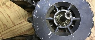
Well, let’s look at our “hedgehog” - since childhood I couldn’t sleep peacefully until I looked at what was inside the new toy. Fortunately, it is easy to disassemble - the structure is held together with four long screws. Inside there are three boards, connected - another board is attached to the sensor board through a connector, which, in turn, is connected to the control board with two cables. Control board - Soldering is normal, the caring Chinese left unwashed flux just in case. There is an unused cable connector in the middle. Also with an inscription suggesting “remove 75R”. I wonder what that means? The middle board is on both sides. The markings on the microcircuits are erased. There is only one - Lattice and alphanumeric code. Google said that it is an American microcontroller manufacturer. I couldn’t find anything on the markings, several symbols were erased and I couldn’t make out them.
The bottom board contains the camera sensor itself. Marking ZS Sensor 100 v1.0. I also didn’t find anything intelligible.
The disassembly turned out to be uninformative. Well, at least my hands don't itch now. And the rest won’t have to go inside. By the way, if someone does climb in, here’s some advice. Mark the cables as they stand. During the first assembly, I assembled it incorrectly; in my opinion, I inserted the contacts on the cable the wrong way into the connector. Well, you can imagine my feelings when it didn’t work after assembly... =) Good, at least it didn’t burn. Be careful!
We’ve dealt with the “hedgehog”, I’ll tell you a little about the “hedgehog”.
From the very beginning I planned to use an old photographic enlarger as a “tripod”. But, as it turned out, finding it is a problem. A survey of my friends yielded nothing; many generally looked at me as if I had been touched. Indeed, this is a thing that is a thing of the past. Looking at ads on “buy/sell” websites is also nothing good, well, I saw several offers there, but in other cities. Doesn't fit. Options for different collective farms were spinning in my head, even with the use of dignity. those. pipes and fittings. And then one fine day for me I was passing through the neighboring yard. I see people taking out old furniture and HE is standing among it. Came up and talked. It turned out that they bought an apartment and were taking out the trash. They gave it away for free. Well, I thanked him, of course. After such events, you begin to believe in the materiality of thought. Moreover, it turned out to be an enlarger of exactly the design I wanted. But I myself threw away my photo enlarger about 5 years ago. I hope someone gave it a second life too. So, this is Leningrad-4, or rather some kind of clone of it. Absolutely identical. I found a photo on the net - this is what he looked like. The condition was “seen a lot in life”, there were no optics, but I cleaned it, lubricated the rubbing parts, everything is fine.
Why did you want this one? It rotates at the top of the leg. It turns out - when we work like this -
When not needed, we remove it -
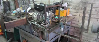
Assembly - everything is simple here, I removed everything unnecessary, made a spacer from a piece of plastic, since the hole on the enlarger is too large in diameter. Three holes, three bolts, the module itself was secured “temporarily” with double-sided tape from the hardware store. From the photo everything is more or less clear. The leg was attached directly to the tabletop. I drilled two holes in it.
At work.
My work monitor is Samsung 930BF. 19” 1280x1024. Connected via VGA. I tried connecting via HDMI to a second Dell FullHD monitor. Everything is working. Only the first time I turned it on, I had to switch the picture to 16:9 in the settings. Then the settings were remembered. A few photos of the resulting device in action. I immediately apologize for the quality - there is no image capture on the device, I just photographed the monitor with a smartphone. A little SMD (focus about 16cm) -
You can estimate the magnification at this focus, the bottom side of the matrix is 38 cm -
Multicontroller (lead pitch 0.4mm), same focus -
The same thing, with a focus of 9cm (working with a soldering iron is still possible, a hairdryer is no longer necessary) -
I work mainly at a focal length of 15 to 20cm. Photo to understand magnification with a tape measure. Micro USB is in focus.
To check soldering, sometimes I do the minimum possible with this design, about 9cm. The microscope itself can focus from a distance of about 4cm. But it is necessary to redo the leg. I'm happy with the current version. The maximum focal length is about 40cm, which captures a field of 2.5cm by 3cm. The focus is adjusted manually using a ring on the lens, while the lower part of the lens remains stationary and does not rotate, good for attaching the backlight. Micro USB with 9cm focus —
Photo of practical application - we will restore the track to the micro USB connector of the tablet.
I use it, it has advantages - convenient mounting, light adjustment. Power supply - directly from the network, converter inside. You can work. It seems to shine well, but without reserve. And I would probably prefer the lighting from a couple of side lights. Sometimes a picture with such purely vertical illumination is somehow unclear, especially when inspecting soldering. If you light it from the side, then it’s good. This is a problem specifically due to the backlight. I'll probably improve it. I’ll add that backlighting is required here, and quite strong. If you turn it on without any backlight, you will see a black screen on the monitor.
Is it convenient to work on it? I’m quite sure. But I’ll say right away that not everyone can work on such a device, when their eyes are looking not at their hands, but at the monitor. I gave it to my friend to try, but nothing good came of it. Although, I think, after some time things would get better, maybe I need to practice. So it would be better to try before making such devices. This did not cause any problems for me; my hands “synchronize” easily. I can do quite delicate work. Let's summarize - the advantages of the device: - no delay when displaying images. — direct video output to the monitor. — a focal length that allows you to work with a soldering iron. — price (relative to a binocular stereomicroscope). — fits compactly into the workplace. Cons: - No image capture. I don't need it at all, it might be important to someone else. — Small field of view with maximum focus. — This is not a binocular stereo microscope =) Am I satisfied? Yes, it is quite. I've been using it for two months. The device allows me to perform tasks that I definitely could not solve with my “glasses” in the form of all sorts of magnifying glasses and other devices. This is still a beta version. I plan to shorten the leg a little and do something with the backlight. But I'm not a professional, this is my hobby. And this is in no way a counterweight to professional microscopes. To warn against a possible holivar, I will say this - a more or less decent stereo microscope is an order of magnitude more suitable thing. But – the price. And the comparison of my needs and capabilities makes my device quite worthy of taking a place on my desktop.
Thank you all for your attention. Health to everyone!
Step-by-step method for assembling a microscope
Select a ready-made cylinder or assemble it yourself to the specified length and to fit the circumference of the selected lenses. Divide it into 2 equal parts. Strengthen the diopter glasses in them.
Paint the insides with black gouache. Glue the lenses in half tubes with cardboard ring inserts. Then make another tube - the future tube - with a diameter so that the two halves with optics fit tightly into it, one above the other. Also paint the inside black.
Finalization of details
An electron microscope can begin to be assembled only after thoroughly checking and finalizing all previously selected parts. The following important points should be taken into account:
- to mount the optics in the base of the bronze bushing, you need to drill two holes with a diameter of approximately 1.5 millimeters, and then cut a thread into them for an M2 screw;
- then bolts corresponding to the installation diameter are screwed into the finished holes, after which small beads are glued to their ends (with their help it will be much easier to control the position of the optical lens of the microscope);
- then you will need to organize illumination of the soldering field of view, for which you will need previously prepared LEDs from the old matrix.
Adjusting the position of the lens will allow you to arbitrarily change (decrease or increase) the focal length of the system when working with a microscope, improving soldering conditions.
To power the lighting system, two wires are provided from the USB cable that connects the webcam to the computer. One is red, going to the “+5 Volt” terminal, and the other is black (it is connected to the “-5 Volt” terminal).
Before assembling the microscope for soldering, you will need to make a base of a suitable size. It is useful for wiring LEDs. For this, a piece of foil fiberglass, cut in the shape of a ring with pads for soldering LEDs, is suitable.
DIY microscope photo
Phone platform
To get a clear picture of the sample, we need the entire setup to be stable. For this we use copper sheet to match the smartphone. The dimensions of the sheet will be only 2 mm larger than that of a smartphone in length and width
Now we have a platform that is suitable for our smartphone. The next step is to make holes for the lens and four screws. Before that, I should tell you something about the design. The phone holder requires a mechanism to allow the setup to be perfectly focused on the observed sample. To do this, I will use four screws that will allow me to change the distance between the lens and the sample. These screws will be placed at the four corners of the holder board. When drilling the hole for the camera, take a moment and mark the spot where the camera is located.
After drilling the holes, it's time to place the four bolt nuts in the corners. Use strong glue to place them perfectly aligned. Be careful not to spill glue onto the screw threads.
After installing the four nuts, it's time to place the lens. Before installing the lens, clean up the rough edges of the drilled hole. Then place the lens over the drilled hole. The 2mm hole fits the lens perfectly and does not fall off. Then glue the lens with a small amount of glue. This is the very difficult part. Be careful, any tiny offset can lead to a false result. The phone stand is ready!
Materials for production
Full list of materials needed for the project:
- -M8 bolt 10-12 cm - 3 pcs;
- nut M8 - 9 pcs.;
- M8 nut with wing - 2 pcs.;
- piece of plywood 7 x 7 cm;
- a piece of plexiglass;
- laser pointer or lens. (2 pieces);
- small LED flashlight.