Sometimes a situation arises that the headphones do not have a plug. For example, it was accidentally broken when trying to disassemble, or melted with a soldering iron while soldering... Or maybe you got the headphones from a friend without a plug. Finding an adequate headphone plug in stores is not so easy, so we will make it ourselves. And it will not be just any other, but a truly original and immortal headphone plug.
We won’t be able to do without a plug completely, but we only need its inner part with contacts. To do this, we cut off the plug from some Chinese headphones lying around the house and unceremoniously pull out the required part.
Of course, if you have a full-fledged plug from other headphones, you can solder it. How to do this is described in detail in the article Headphones Not Working? DIY headphone jack repair .
Why reinvent the wheel then? The headphone plug is its weakest point, and in the vast majority of cases, repairs come down to resoldering the plug. The proposed option can significantly extend the life of the connector.
Checking the headphones
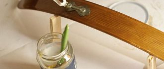
Having found the inside of the headphone plug from the donor, the first thing we do is solder it to our headphones and see if they work at all and whether it makes sense to torture them further 
If you have difficulties and cannot determine which wire goes where, then I advise you to look at another article, which gives many examples of the colors of headset wires:
Repairing the headset jack or five wires on four contacts
If something doesn’t work after soldering, we look for the problem. And if everything is fine, then we move on to plastic pipes
Connector purpose
It is the connector that serves as the connecting device between the rod and the fishing line, which allows you to securely secure the tackle and quickly change it if necessary. In this case, the fisherman will not have to tie extra knots and reconfigure the equipment. The loop at the end of the equipment is inserted into a special recess and closed with a movable cap. This is where all manipulations to equip the fishing rod end. All that remains is to put the desired bait on the hook and throw it into a promising place.
Any specialized fishing store offers a very large selection of connectors. But this is not because manufacturers want to diversify the design. The tips of the rods have different thicknesses, which is why the connectors are produced in different diameters. In addition, they can be steel or plastic, which affects both the quality of the product and the price.
Material
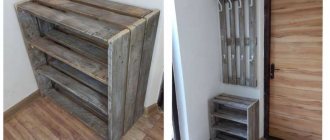
Yes, you heard right, you will need a piece of plastic pipe. 3-5 centimeters long and any diameter. This will probably be found at home in everyone who has installed such pipes, and if not, then you can ask a neighbor, friend or hardware store seller for trimmings.
These pipes turned out to be an ideal plastic option. Before them, polyethylene was tested from bottles, caps, some jars for medicine... But only then did it dawn on us that these pipes were originally designed for melting. And besides, they conduct heat very poorly, so you won’t be afraid of damaging the connector or getting burned while holding it in your hands during all the activities.
Having found a piece of pipe, cut it into strips using a sharp knife. It is convenient to work with such pieces.
Carefully! The plastic is quite viscous and you can easily get hurt.
Tread
Since cable damage is a very common problem, special devices have been invented to protect wires. In fact, they are needed to prevent ruptures, but they are also suitable in case of wiping that has already begun. On the same AliExpress, upon request “cable protector” or “cable protector” you can find many options for such devices: both for chargers and for headphones. They are mainly designed to protect the most fragile part of the wire - one of its ends, but there are also options for strengthening the entire cable.
www.aliexpress.com
Damaged chargers and headphones will be able to last for some time if you use any of these methods. This is especially true if buying a new cable is quite expensive: for example, a charger for a MacBook.
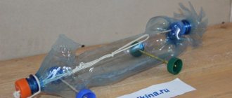
We melt
We brazenly and unceremoniously melt the edge of a piece of pipe to the connector:
All photographs presented in this article are the first attempt to use this method. Everything was invented on the fly.
It was decided that if we were to do it, we should make an L-shaped connector, which would be less susceptible to jeans being killed by pockets.
Homemade connectors
As already mentioned, it is best to choose a connector when purchasing a fishing rod. But it happens that the rod is already at home, for example, it’s a birthday gift from a good friend who knows your hobby, and going for a connector with a fishing rod is not always convenient. And then the question arises: is it possible to make a connector with your own hands?
The answer is simple: you can. A homemade connector can be of several types, the main thing is that the basic principle is observed - quick replacement of equipment.
From wire
A piece of soft wire is bent in half to form a loop. The ends are tied with nylon thread to the tip of the rod. The thread is impregnated with quick-drying waterproof glue. Instead of wire, a piece of thick fishing line can be used. Fastening of the equipment is carried out using the “loop-to-loop” method.
The wire loop is reliable, but not very convenient when changing equipment
The relative disadvantage of this homemade connector is only one. In order to tie a new rig, you will have to pull the entire fishing line through the loop at its end. And this is several meters with a hook, sinkers and a float. And it takes longer, and you can get confused. Otherwise, this method is quite reliable.
Comic
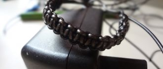
As you can see from the comic, by moving a soldering iron along a piece of pipe, you can bend it where and how we need. Then, by running a soldering iron over the surface, you can level it and give it the final look. When the desired shape is achieved, cut off the excess from the contact side.
In my opinion, such a connector is practically indestructible. It is much more likely that the wire will come out of position as it approaches the connector. And to reduce this probability, it was decided to use a spring. We will borrow it from a clicky ballpoint pen.
The spring should wind with difficulty, expanding at the connector. Then later, if you apply a soldering iron to it, it will shrink to its original diameter and melt into the connector.
Carefully!
The spring conducts heat very well and you can accidentally melt the wire sheath with it.
After everything that had been done, the thought came to me that it would be better if, before wrapping it in a plastic pipe, we put a 2-3 centimeter long thermal casing on the outgoing wire. In this case, you don’t have to worry about melting the wire braid when molding the connector and putting on the spring. Yes, and this would give it even more strength.
Advantages and disadvantages
What homemade bite alarms are there for bottom gear?
We should probably start with the shortcomings. There are only three of them, and the first two can be easily avoided by choosing the right product.
- Defects that can lead to line cutting.
- Cheap plastic connectors are not durable.
- Reduces depreciation. Which, however, is not very significant due to the short length of the connector.
There are far more advantages:
- Quick change of equipment. Including winding up the old line and unwinding the new line, it takes no more than a minute.
- Easy to install.
- Reliability of fastening.
- No extra knots when tying fishing line.
- Compactness.
- Durability.
- Price. Even the most expensive connector is several times cheaper than lost gear.
There are many more advantages, and the question of whether or not to use a correctly selected connector disappears by itself.
Extending the cable using a splitter
This method of connecting and extending the TV line is used less often than others. It is carried out through a special block called a splitter.
The device is designed to distribute a signal to two tuners from one antenna.
- The connection method itself is not very different. First, the ends of the wire are cut, the plugs are put on, which are then screwed to the splitter.
- When connecting, you should follow the following instructions: First, connect the end of the cable coming from the antenna to a single socket marked IN.
- Next, alternately connect the ends coming from the receivers to the outputs marked OUT. There may be two or three.
About the colors of wires in headphones
Headphone wire colors are usually standardized. The wire colors for standard headphones with 3 wire types are shown in the photo below.
However, there are still manufacturers who use non-standard wires for soldering headphones and marking channels. For example, Apple uses two-color wire markings in its AirPods headphones.
In such cases, the Internet or the method of checking with a 3-volt battery or multimeter comes to the rescue.
When voltage is applied (with a battery or a multimeter in ohmmeter mode) between the contacts of the speaker, a rustling sound will be heard in it. It's simple. It’s more difficult with headsets, especially if they have buttons. This is where circuitry comes into play. Because manufacturers often use a minimum of pairs of wires to transmit a large number of signals.
Extending the cable using a splitter
This method of connecting and extending the TV line is used less often than others. It is carried out through a special block called a splitter.
The device is designed to distribute a signal to two tuners from one antenna.
- The connection method itself is not very different. First, the ends of the wire are cut, the plugs are put on, which are then screwed to the splitter.
- When connecting, you should follow the following instructions: First, connect the end of the cable coming from the antenna to a single socket marked IN.
- Next, alternately connect the ends coming from the receivers to the outputs marked OUT. There may be two or three.
How to make a plug for a TV antenna yourself: instructions on how to do everything correctly
The plug is used to connect antennas and set-top boxes to televisions, VCRs and DVDs. Cables from this connector typically carry analog TV signals, and the plug's connection is easily identified by its thread. The plugs are available with threads and without threads, both of which will fit into the antenna's threaded socket.
How to make a plug yourself
A coaxial cable used to carry electronic signals to a TV or other electronic device ends in a plug called an F connector, which is the connector that actually connects to the TV or wall socket.
Tools and materials you will need:
- Knife
- Wire stripper
- Crimp or swivel F connector
- Cable crimp (for connectors only)
Instructions: DIY plug
First, disassemble the TV connector into individual parts by unscrewing the top part from the main body. Inside there will be a female connector that will slide over the exposed copper section with the cable and clamp to hold the cable in place and prevent it from being pulled out.
REFERENCE! Before you go any further, put the female threaded top on the cable because it's not worth putting it all together and you know you have to take the whole thing apart to put the plug on!
Then, very carefully, run a knife along a 2-inch length of the outer sleeve of the coaxial cable. Not deep enough to cut through the sleeve, or you can cut the braid from the bottom. Using your fingernails and twisting slightly, open the outer sleeve to reveal the braid. Then cut off the excess outer sleeve.
Place the braid over the top of the inner sleeve. Slide the sheet cable clamp onto the inner grommet next to it and press it firmly against the outer grommet, holding the braid inside. Gently press the leaves closed around the outer sleeve to lock it in place and hold it firmly in the nest. This will help prevent the cord from becoming disconnected, falling out, or being pulled out by mistake.
Take the fork and press it against the clamp. You will see that the plug is pushed inward slightly to form a clamp. Cut the inner sleeve where it meets the end of the plug so that the plug slides slightly over the leaf clip.
Strip the insulation from the inner core, leaving 2mm of insulation to slide inside the plug. Take the plug and place it on the end of the cable, making sure that the copper wire of the inner core goes down into the thin hollow sleeve at the end of the plug.
IMPORTANT! Now that the plug is in place at the end of the cable, take the main body and slide it onto the plug. The end of the leaf clip should poke through the end of the main body slightly.
With everything now screwed on, you're ready to go! All that remains is to connect the cable to the TV and make sure that everything works as it should.
setafi.com
Replacing the connector on a fly rod
If a connector breaks, it should be replaced. This is done like this:
- 1. A ring made of strong thin wire is inserted into the nozzle, snapped into place, and pulled back so that the connector bends slightly.
- 2. The body of the nozzle is carefully heated from all sides using a shadow or a candle.
- 3. When the glue becomes soft, carefully remove the device using a wire ring.
The dismantling process takes no more than a minute. To install the new connector, you will need sandpaper and glue that dries for a few minutes. Clean the joint with paper, apply glue to the surface, spread it evenly over it, put the nozzle on tightly and leave for three to four hours. The time depends on the type of glue.
Design and selection of fishing rod connector
The connector is an attachment with which the fishing line is attached to the tip of the rod. The device has a cut and a slider-lock. The loop of fishing line is inserted into the cut, then snapped into place with a slider. This completes the entire process of replacing equipment.
Types of connectors are divided:
- by the thickness of the rod tips;
— by diameter;
— by weight;
- according to the material.
Nozzles can be plastic or made of light stainless steel. It is advisable to choose connectors when purchasing a fishing rod in order to correctly determine their diameter. The following rules should be taken into account:
- 1. It is necessary that the device is put on the tip with force. If it dangles, the nozzle will quickly become unusable.
- 2. There should be no sharp edges, burrs or cracks on the connector. They can lead not only to line breakage when fishing for trophies, but also to failure of all other equipment.
- 3. You should not purchase attachments that crack when squeezed with your fingers. They have low strength and will not withstand even small loads.
There are removable connectors on sale, which are plastic or rubber rings with carabiners. Such attachments are reliable, but when fishing you need to regularly check whether they have slipped off the tip of the fishing rod or whether the carabiner has come loose. The fishing line attached to such a connector is not changed. They simply take another rig with a nozzle pre-attached to it and put it on the tip.
You should not save money by purchasing the cheapest plastic connectors. They don't last long. A correctly selected reliable nozzle will allow you to:
— effortlessly change fishing line in 5 minutes;
— securely fasten the equipment;
— get rid of the need to knit extra knots on the fishing line;
— avoid unnecessary costs caused by equipment breakdowns.
Checking the connection
There are two ways to check the correctness and quality of the connection.
- Use a measuring device to check if there is a short circuit and find out the signal level from the antenna. If there is no short circuit, and the signal is received, it means that the connection is completed correctly, you can tune in television channels.
- Connect the TV to an over-the-air receiver, try setting up digital TV, and additionally check the TV signal level in the manual search menu.
The TV signal level should only be viewed on working channels (multiplexes) in your area. Therefore, you first need to determine which channel number is broadcast from the nearest repeaters. Go to the digital broadcasting coverage map and use the search to find your home. You need to enter the full address of the house, click on the “Find” button and select the house on the map. Next, the parameters of the towers will appear, where the TVC numbers will be written.
The value for each channel is set one by one. Look at the reception level, and then draw conclusions. If the signal is too weak, you should try to adjust the antenna more accurately or completely replace the receiver with a more powerful one. If a passive type of ethereal device is currently working, you need to think about installing an active one.
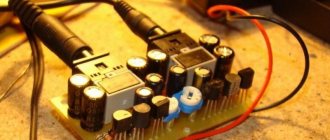
How to remove the supply voltage, for example 5 V, from the USB-C connector (USB Type C)? All the latest laptops, smartphones, tablets, power banks and travel chargers usually come with USB-C ports. Even the USB-C port on a cheap charger (Power Bank) is capable of supporting DC voltages up to 12 V. USB specifications provide information on the implementation of higher levels of power supply available through USB Type C connectors. With regular USB everything is clear, 4 pins , where the 2 extreme food. But in the new one, everything is no longer so simple, so we’ll figure it out.
How to solder headphones with a microphone
To properly repair headphones with a microphone, you need to know the connection circuit and the purpose of the four-pin jack pins. A typical soldering diagram for a microphone plug and a button in a stereo headset is shown in the picture below.
For most manufacturers of simple headsets, the microphone should be soldered as in the picture.
How does a four-pin jack work?
A four-pin jack has the same structure as a three-pin one. Coaxial design and separation by plastic bushings with standard sizes into 4 wires is present on all TRRS plugs. The pinout of 4-wire plugs differs by manufacturer. There's a lot of people here. To correctly replace the headset plug, look at the pinout of the minijacks in the picture.
The picture shows the following symbols: M - microphone, G - common contact, R - right channel, L - left channel. Now it’s clear that soldering headphones onto 4 wires is not an easy task. The wiring diagram of the plug greatly depends on the brand of the headset.
Connecting the cable to the antenna
Connecting the TV cable to the antenna should be carried out in compliance with the rules for switching electrical appliances, guided by the diagrams available in the technical data sheet of the TV. To complete the work you will need:
- splitter;
- antenna cable;
- antenna amplifier;
- wire cutters;
- sharpened knife or scalpel;
- soldering iron
The cable is connected directly to the TV antenna using screw terminals.
The cable, splitter and amplifier must be installed next to the separated cable. In an individual home, the best place to place all appliances is the attic. The end of the cable coming from the antenna is connected to the amplifier through a special terminal. From the amplifier the signal goes to a splitter, to which the television receivers in the house are connected. When connecting to a satellite dish, you will need to use a receiver to which a cable is connected via the antenna connector. Preparing the cable is similar to cutting it before connecting it to the plug.
Standard plugs
According to Wikipedia, there are the following types of jacks:
- TS/TRS 6.3mm diameter (for microphones, electric guitars, mixing consoles, old professional headphones, etc.)
- TS/TRS/TRRS with a diameter of 3.5 mm (the most common, used for modern headphones, microphones, acoustics, flashes, etc.)
- TS/TRS/TRRS with a diameter of 2.5 mm (for mobile phone headsets, webcams, flashes, etc.)
There is also a type of TRRRS connector, which is used to transmit not only audio, but also video signals.
By the way, this designation is adopted according to the principle: T - Trip (latch), R- Ring (ring), S - Sleeve (sleeve).
How to properly solder a new plug to the headphones, observing the pinout of the wires
To properly solder a headphone or headset plug, you need to know the pinout. It is shown in the table below and taken from the website about connectors.
Minijacks for speakers and microphones also have the same pinouts for 2- and 3-pin plugs.
Plugs and their pinouts for more specialized devices (video cameras, headsets) by manufacturer (Nokia, Samsung, Sony, Panasonic) are shown in the following table.
How does a three-pin jack work?
A regular three-pin stereo jack is designed according to the coaxial principle. Each contact is located in a dielectric sleeve (bushing) and is located inside another sleeve.
The plug contacts are separated from each other by plastic bushings. So this plastic is afraid of overheating, it begins to melt and the contacts will dangle. So if you want to solder a headphone plug, you should remember about overheating the contacts with a soldering iron.
Digital cables
There are several digital cables, but most are computer standards. For television, a separate universal connector has been developed, which we will now analyze.
HDMI cable
HDMI (High Definition Multimedia Interface) can easily be called the pinnacle of the evolution of television cables. It transmits high-definition digital video signals as well as multi-channel audio. Modern versions of this cable are able to protect transmitted information from copying.
Essentially, this is a computer DVI standard supplemented with sound, so when connecting a PC to a TV, you can use both connectors, but you first need to get an adapter.
When switching to such a connection, look for the corresponding item in the TV menu.
This connector was able to replace all previous analogues, thanks to which modern multimedia devices have become much smaller in size, since there is no longer a need to place outdated connectors and boards for them in the device body. However, it would not be amiss to note that a device that has more than one output will continue to function even after one of them fails, which cannot be said about mono-connected options.
Here are the main parameters of HDMI cables:
- HDMI has high throughput from 4.9 Gb/s for version 1.0, to 48 for version 2.1. New models allow you to watch video in very high resolution (8K) and play 3D format on appropriate TVs.
- The length of the standardized cable does not exceed 10 meters, so the quality will not be lost during transmission. There are also non-standard options, up to 35 meters, but for them it is better to additionally install signal amplifiers (repeaters).
- Support for CEC and AV.link control protocols.
- They have a shielding braid and ferrite rings (not on all models) along the edges of the cable to cut off interference.
You can find out more about the technical characteristics of the cable version on the manufacturer’s website or, for example, on Wikipedia. Full tables with all the necessary data for each version are available there.
Among the disadvantages, it is worth noting the high price, especially for branded options equipped with all degrees of protection and with connectors coated with precious metals.
We will simply recommend that people who want a better picture purchase this cable, if this has not been done previously, and your system supports such a connection. The image quality will increase several times, provided that a high-definition signal is supplied to the TV.
Today, many channels are moving to HD broadcasting, and it is gradually becoming an accepted standard. We assure you that watching any program about wildlife on the Discovery channel in this quality will be much more interesting and enjoyable.
Also, you can easily connect your computer to your TV without any hassles with wires and watch movies in high quality directly from the Internet.
Now you know exactly what a television cable is, and which one is best to choose from the whole variety. The development of technology does not stand still, and every day new requirements for standards arise. Today, HDMI meets all requests, although who knows, maybe tomorrow they will come up with ultra-high-speed holographic projectors, or something like that, and this standard will also begin to fade into oblivion.
How to select and connect a TV plug
19.10.2018
Often the cause of a malfunction of a television device is damage to the antenna cable or the plug connecting the TV device to the periphery.
After reading the tips presented in the article on choosing and connecting a plug for a TV antenna, the user will be able to independently repair the indicated breakdown.
TV plug
If previously, to connect an antenna cable to a television plug, it was necessary to resort to soldering or select peripherals with suitable connectors, but now the user can assemble the necessary structure using available tools.
Modern manufacturers of TV components make plugs according to the international F-standard, which is a kind of bushing that is screwed onto the antenna wire.
Which antenna plug is better?
For connecting to a coaxial wire, the F-plug is best suited, among the main advantages of which are:
- the presence of a shielding braid around the central core - the braid serves to ensure uniformity of wave impedance and prevents additional losses in the quality of the television signal;
- compatibility with any type of television signal - the F-plug works equally well with a digital antenna and cable television;
- ease of installation - any user can handle the connection, as you can see after reading the following sections of this article.
Since installing the antenna plug of the previous generation will require much more effort, only F-plugs, the use of which is more appropriate, will be considered below.
How to prepare the cable
Before installing the F-plug, you must prepare the antenna cable for connection. After removing the old plug from the wire, the user must cut the outer insulation of the wire in a circle - when removing the protective layer, the braid cannot be damaged. The length of the incision should not exceed 2 centimeters.
Next, you will need to bend the insulation in such a way that the TV cable retains its shielding properties: part of the metal “hairs” of the insulation should be hidden only when further connecting the F-plug, and not smoothed to the body of the wire. The compliance of the insulation depends on the manufacturer of the peripheral and the physical strength of the user.
How to connect the antenna F-plug and cable
It is worth saying that since there are three sizes of F-plug, before purchasing a connecting element you need to make sure that the plug and the antenna cable are compatible. Although the sizes vary, each F-plug supports analog, digital, and satellite signals. There are two ways to attach the F-plug to a television cable: the first involves wrapping the shielding braid, and the second involves cutting off the sheath at the point of contact of the periphery.
The first option is more reliable, but requires much more effort and accuracy from the user.
If you cannot wrap the braid for one reason or another, you must follow the instructions below:
- Cut part of the television cable. The user will need to cut a few centimeters of the outer sheath of the cable so as not to damage the braided screen. To carry out this operation, it is recommended to use a sharp utility knife and not to apply a large amount of physical force.
- Bend back the protective shell. When the wire is “bare”, you will have to remove the excess part of the protective sheath.
- Removing an additional layer of wire protection. Depending on the cable type, the user will need to remove the copper braid or aluminum foil at this stage. It is worth noting that some wires are protected by both a copper and an aluminum layer.
- Return half of the previously folded layer of foil back into place. Interestingly, during production, to strengthen the structure of the wire, a layer of polyethylene is applied to aluminum foil, which is almost impossible to clean. Once the cable is connected to the plug, the plastic can create interference and interfere with the transmission of the television signal - to avoid possible loss of picture quality, the user must place the conductive part of the wire outside.
- Equalize the diameters of the connected antenna cable and F-plug. Sometimes the hole in the internal thread of the F-plug has a larger diameter compared to the “bare” end of the cable - to eliminate the difference in diameters, you will need to wrap 2-3 layers of insulating tape on the wire. It is important to note that after this operation it will be necessary to remove part of the homemade insulation from the central conductor of the cable.
- Screw the metal part of the F-plug onto the antenna wire. To avoid stripping the threads of the elements being connected, screwing should be done by hand rather than using tools.
- “Bite off” the central core of the wire. It is important to say that as a result, the conductor should protrude by 2-3 millimeters.
- Screw the “head” of the F-plug onto the assembled structure. Next, the user can start connecting the antenna to the corresponding jack on the TV.
If, when connecting the F-plug to the television socket, the antenna cable will have to be bent at an angle of more than 70 degrees, then in order to avoid chafing of the wire, it is recommended to use a plug of an angular design, which differs from the usual one only in its external shape. The installation process for straight and angled plugs is similar. If the user plans to use an old type of plug, then it is likely that when connecting the elements it will also be necessary to transfer the plastic cover from the plug to the cable. To connect a non-certified plug to the wire, you will need a soldering iron.
Conclusion
Now the owner of the TV device knows how to correctly connect the antenna F-plug to the cable network. The process of repairing an old wire is not anything complicated - even a user who is far from repairing electrical equipment can cope with restoring a television system.
How to select and connect a television plug Link to main publication
televizore.ru