The headphone amplifier was created not just as entertainment, but out of real necessity, because you often have to travel by public transport. Unfortunately, listening to music and audiobooks on 32-ohm headphones from a regular mp3 player was pointless. It only produced 2 x 5 mW even at 16 ohms, so at 32 ohms you could hear ambient sounds instead of music.
Stereo sound amplifier on TDA7262
Hi-Fi amplifier for two channels.
This microcircuit has a wide supply voltage range, and the output current reaches 3.5 amperes. A standby function and protection against short circuits and overheating during operation are also available.
Limit characteristics of the microcircuit
| Supply voltage Upit | 25 V |
| Output peak current | 4.5 A |
| Power dissipation Prass | 30 W |
| Working temperature Trab | -20…+85 °C |
Loudness is not the main goal
Many people believe that a headphone amplifier is only needed to listen to music louder. In fact, the value of this gadget is somewhat greater. Any headphones are a complex load for the sound source. This statement is even more true if the headphones are armature, hybrid, iso-/ortho-dynamic or more exotic.
The main problem is usually a lack of output current from the sound source. On the other hand, most modern sources cannot produce a signal of sufficient level to drive high-impedance headphones, such as studio headphones .
The picture is further spoiled by the fact that any speaker has parasitic parameters - inductance and capacitance. They create certain problems for the sound source. The impedance of headphones depends on frequency, and the sound source must be able to cope with this. There are other important aspects for sound, but it won’t go deep into the technical jungle.
To summarize, the main task of a headphone amplifier is to match the signal source to the headphones. At the same time, the original sound quality must be preserved, and the output signal must have greater power than the input.
Amplifier 50 W
A simple single-channel circuit based on TDA1514.
Chip characteristics
| Parameter | Meaning |
| Upit1 | +10…+30 V |
| Upit2 | -10…-30 V |
| Iout | 5 A |
| Irest | 56 mA |
| Pout | 50 W |
| Rin | 20 kOhm |
| Gain | 30 dB |
| Frequency band | 20-25,000 Hz |
| Harmonic distortion | 0,01 % |
| Rload | 8 ohm |
Pin assignment
| Pin number | Purpose |
| 1 | Non-inverting input |
| 2 | Protection circuit output |
| 3 | Supply Voltage Shutdown Circuit Output |
| 4 | Supply voltage (-27.5 V) |
| 5 | Exit |
| 6 | Supply voltage (+27.5 V) |
| 7 | Power amplifier feedback and correction input |
| 8 | Output shutdown circuit output |
| 9 | Inverting input |
Tube headphone amplifier housing
The most commonly used material is aluminum to create the box. Wood is used much less often, although it significantly improves the sound. Aluminum material is chosen not only because of its attractive appearance, but also because the material is quite dense and light. It is best to perform assembly using a welding machine, and then carefully process the seams.
We recommend reading: Temperature sensor: types, purpose, device, typical circuits
After the box is assembled, a partition is installed. A small hole is made in it through which the wires will pass. On the box they mark the location of all the elements according to the diagram and begin the process of assembling the structure.
TDA8567q 4x25 W
Hi-Fi class bridge amplifier for four channels.
There is protection against short circuit of the output stage and thermal protection with a reduction in output power when overheated. The microcircuit also has protection against voltage fluctuations and a shutdown mode. This microcircuit also has an on/off mode for the input signal (Mute mode), and protection against “clicking” when voltage is applied to the circuit.
Chip characteristics
| Parameter | Meaning |
| Upit | 6-18 V |
| Iout | 7.5 A |
| Irest | 230 mA |
| Pout | 4x25 W |
| Rin | 30 kOhm |
| Gain | 26 dB |
| Frequency band | 20-20000 Hz |
| Harmonic distortion | 0,05 % |
| Rload | 4 ohm |
Pin assignment
| Pin number | Purpose |
| 1 | Supply voltage |
| 2 | Exit 1+ |
| 3 | General |
| 4 | Output 1- |
| 5 | Output 2- |
| 6 | General |
| 7 | Exit 2+ |
| 8 | Supply voltage |
| 9 | Diagnostics |
| 10 | Input 1 |
| 11 | Entrance 2 |
| 12 | General signal |
| 13 | Entrance 3 |
| 14 | Entrance 4 |
| 15 | Mode selection |
| 16 | Supply voltage |
| 17 | Exit 3+ |
| 18 | General |
| 19 | Output 3- |
| 20 | Output 4- |
| 21 | General |
| 22 | Exit 4+ |
| 23 | Supply voltage |
The internals of a tube amplifier
They start by laying out the wires and filament lines of the lamps. Solder the parts directly onto the output of the lamp panels. It is better to use high-quality elements as a capacitor, and fastening is carried out using hot-melt adhesive.
Once all the elements are attached, you need to carefully check the design with the diagram and test it. If everything is assembled correctly, but the voltage is very different (more than 10 times), then it is better to throw away the lamps.
Stereo amplifier 12 dB
The TDA8199 can be used with both electronic volume controls and simple potentiometers of the appropriate sound class.
Characteristics
| Supply voltage Upit | 10.8 - 13.2 V |
| Current consumption Ipotr | 21 - 28 mA |
| Gain output/input | 12 dB |
| Audio input impedance Rin | 22 - 1000 Ohm |
| Harmonic coefficient Kr | 0,35 — 1 % |
| Audio output impedance Rout | 30 - 1000 Ohm |
| Output noise voltage Uout noise | 30 µV |
Chip Limits
| Supply voltage Upit | 16 V |
| Working temperature Trab | -55…+125 °C |
| Storage temperature | 0…+70 °C |
SMD version of the amplifier
And another version on planar parts. The printed circuit board came out 28 x 38 mm. Assembly on SMD equivalents of transistors from the BC5xx series. However, for the sake of improving sound quality, standard capacitors are used.
Note that there is volume control on two separate potentiometers, separate left and right channels. Of course, double logarithmic potentiometers can be installed (according to tradition), but each ear has its own hearing level, and the balance of the headphones (parts) is not ideal, so we recommend doing just that. General volume adjustment is done on the mp3 player.
ULF TDA8198 12 dB
The TDA8198 chip is manufactured in a DIP14 package and is used in high-end equipment.
The dynamic signal level is 90 dB.
There is protection of the output stage from short-circuit and static.
Chip characteristics
| Supply voltage Upit | 10.8 - 13.2 V |
| Current consumption Ipotr | 24 - 32 mA |
| Reference voltage Uref | 6.9 V |
| Output noise voltage Uout noise | 300 µV |
| Harmonic coefficient Kr | 0,3 — 1 % |
| Audio input impedance Rin | 22 kOhm |
| Audio output impedance Rout | 10 - 300 Ohm |
Chip Limits
| Supply voltage Upit | 16 V |
| Working temperature Trab | -55…+125 °C |
| Storage temperature | 0…+70 °C |
What is the “trick” of this amplifier?
What is the “trick” of this amplifier?
The scheme is not new at all. It is known from datasheets of the 90s. But the interesting thing about the circuit is that both op-amps amplify the same signal. But this is not a bridge connection. The output signals of both op-amps are in phase, due to which their output currents add up.
This inclusion solves the problem of the low output current of many op-amps. This significantly increases the number of op amps that can be used in the amplifier. Now it is enough that each operational amplifier can provide an output current of 35-40 mA, instead of 70-80 in the case of one op-amp per channel.
The maximum output current value is always given in the datasheets on the op-amp.
Device base
Beginner radio amateurs first of all ask themselves: what can they use to assemble a simple sound amplifier at home? The operation of the device is based on transistors or microcircuits, or a rare option is possible - on lamps. Let's take a closer look at each of them.
Transistors
The advantages of transistors are low power consumption. The device produces excellent sound performance, is easily integrated into any equipment and does not require additional configuration. In addition, there is no need to search for and use complex microcircuits.
Lamps
Today, the outdated assembly method based on tubes provides high-quality sound, but has a number of disadvantages:
- increased energy intensity
- dimensions
- weight
- cost of components
Microcircuits
The TDA series microcircuit and a similar one can be purchased in stores or you can use a microcircuit from an unnecessary TV.
Using car amplifier chips with a 12-volt power supply, it is very easy to achieve high-quality sound without the use of special skills and with a minimum of parts.
ULF TDA8196 12 dB
A simple power amplifier circuit using TDA8196. Scheme for a beginner radio amateur. Doesn't require many parts and is easy to assemble. Miniature bridge low frequency power amplifier with electronic volume control.
There is protection for the output stage against short circuits and thermal protection against overloads. And of course, protection against static. The amplifier can be adjusted either with a potentiometer or with a simple electronic volume control.
Specifications of TDA8196
| Supply voltage Upit | 10.8 - 13.2 V |
| Current consumption Ipotr | 12 mA |
| Reference voltage Uref | 6.6 V |
| Audio input impedance | 10 - 13 kOhm |
| Audio input impedance | 0.2 - 1 kOhm |
| Harmonic coefficient Kr | 0,4 — 1 % |
| Output noise voltage | 40 µV |
Chip Limits
| Supply voltage Upit | 16 V |
| Working temperature Trab | -55…+125 °C |
| Storage temperature | 0…+70 °C |
Let's simplify our life
Those who are just discovering electronics and high-quality sound will certainly be pleased with the fact that they will need to assemble an amplifier part. And even then, a printed circuit board and all the other necessary information will be given later, ready for repetition.
The remaining units will be purchased ready-made. This will greatly simplify and reduce the cost of the task without any loss of quality. Self-assembly of such units will significantly complicate the task. And it will not be possible to do without them in the planned design.
In addition, with today's scale of production of various modules, the cost of purchasing parts for such a module is more expensive than the cost of a finished module. A reasonable question arises: why bother?)
TDA7265 and two inclusion options
There are two options for turning on the microcircuit.
- Large power range (+-25V);
- Bipolar power supply circuit;
- Power 2x25 W
- There is a silent mode and a standby function;
- Thermal protection against overheating during amplifier operation;
- There is short-circuit protection.
Bridge version of the amplifier on TDA7265
Chip characteristics
| Supply voltage Upit | 25 V |
| Output voltage in idle mode | 80 - 130 mV |
| Current consumption in idle mode Ipotr | 65 - 120 mA |
| Bias current at the non-inverting input Ibias | 500 nA |
| Output power Pout | 20 - 25 W |
| Harmonic coefficient Kr | 0,01 — 0,7 % |
| Gain (Open Loop) | 80 dB |
| Input resistance Rin | 15 - 20 kOhm |
| Shutdown temperature | 145 °C |
Limit parameters of the microcircuit
| Supply voltage Upit | 25 V |
| Output peak current | 4.5 A |
| Power dissipation Prass | 30 W |
| Operating temperature Trab | -20…+85 °C |
| Storage temperature Tstore | -40…+150 °C |
Step-by-step amplifier assembly process
Having prepared all the necessary tools, understood the diagram and created a layout, you can proceed to the assembly process.
Reference! To improve the sound, they use a wooden chassis rather than a metal one. Plywood would be a good option.
- The first step is to determine the location of the elements. Much attention should be paid to the location of the light bulbs and drilling holes for them.
- All elements that are present in the diagram are arranged according to it.
- First, the filament power buses are applied.
- A filament is connected to each of the lamps.
- Upon completion of these works, passive elements are connected.
This is what concerns the process of assembling a tube amplifier with your own hands.
Bridge to TDA7240
A miniature but quite powerful low-frequency power amplifier, made using a bridge circuit.
The amplifier has:
- Protection of the output stage from short circuit;
- Thermal protection in case of overload;
- Reliable protection against surges up to 28 V.
Chip characteristics
| Upit | 6 - 18 V |
| Iout max | 4.5 A |
| Irest | 150 mA |
| Pout | 20 W |
| Rin | 50 kOhm |
| Gain | 40 dB |
| Frequency band | 30 - 25 kHz |
| Harmonic distortion | 0,5 % |
| Rload | 4 ohm |
Pin assignment
| Pin number | Purpose |
| 1 | Distortion Compensation Circuit Output |
| 2 | Output of correction scheme |
| 3 | Entrance |
| 4 | General |
| 5 | Output 1 |
| 6 | Supply voltage |
| 7 | Exit 2 |
Component quality
Component quality
Capacitor C1 must be non-polar. Better polypropylene or film. It is better to use ceramic capacitor C2. The accuracy of capacitors is not so important, but it is better to use an accuracy of at least 5%. Resistors should preferably have an accuracy of no worse than 1%
Good microcircuits are not cheap. For example, for two original OPA2604 , which were offered in the original scheme, you will have to pay about $23.
But it is not at all necessary to immediately purchase the most expensive. To begin with, you can supply something from the assortment of the nearest radio parts store, and gradually replace them with higher quality components. The board will work on any parts.
Prices for operational amplifiers vary widely and more expensive does not always mean better sound. To begin with, you can install something inexpensive and accessible, for example, the beloved NE5532 ($0.3). It is highly desirable that it be made by Phillips.
Subsequently, you can play with replacing the op-amp as much as you want. If we consider op-amps of a higher class, then OPA2134, OPA2132, OPA2406, AD8066, AD823, AD8397… have proven themselves well for sound.
Do not order the cheapest microcircuits from AliExpress and other Chinese stores. There are a lot of fake chips out there. They will work as expected, but it may not be the OPA2134 you ordered, but a rather cheap TL061 labeled OPA2134...
But I managed to find a store that sells truly original microcircuits. And in general it has very high quality audio components. Including the top ones. I highly recommend this store.
ULF circuit on TDA7236
The microcircuit is in a minidip (4+4) package.
Chip characteristics
| Supply voltage Upit | 1.8 - 24 V |
| Current consumption with idle mode Ipotr | 5 mA |
| Output power Pout | 1.7 W |
| Harmonic coefficient Kr | 0,3 — 1 % |
| Gain (closed loop) | 38 dB |
| Input resistance Rin | 100 kOhm |
Limit parameters
| Supply voltage Upit | 28 V |
| Output current Iout | 1 A |
| Power dissipation Pdis | 500 mW (SZIP package), 800 mW (SSOP package) |
| Temperature Tb | 40…+150 °C |
Transistor amplifier
The advantage of these amplifiers is their simplicity and the absence of multi-component complex circuits. If you use germanium transistors for manufacturing, you can freely integrate them into any audio equipment.
However, they also have significant disadvantages. For example, the final device will have quite large dimensions. Or the sound quality will be acceptable only with proper settings, since there will be a direct dependence on the “Background”.
For assembly you will need a shielded cable or an additional device to suppress noise and interference.
Amplifier based on TDA7052
Used in portable audio equipment
An amplifier assembled according to this scheme has a number of advantages:
- No external elements needed;
- Minimal interference when turning on and off;
- Sufficiently high stability of operation when amplified;
- Low power consumption;
- No need for an additional radiator
- There is short-circuit protection.
Chip characteristics
| Supply voltage Upit | 3 - 18 V |
| Current consumption in idle mode Ipotr | 4 - 8 mA |
| Gain factor Kusil | 38 - 40 dB |
| output power | 1.2 W |
| Harmonic coefficient Kr | 0,2 — 1 % |
Tube headphone amplifier
In order to understand whether it is worth constructing such a scheme or not, it is worth examining a number of its main advantages. It is the strengths that will help determine what a tube headphone amplifier is needed for.
Advantages
Some of the main advantages include the following:
- The simple design of the tube amplifier does not cause repair problems.
- Sufficiently long service life.
- No hissing or white noise effect.
- Smooth system sound, which is ensured by smooth transitions and high dynamic range.
- Resistance to high temperatures.
This is one of the main advantages of the lamp system.
A pair of amplifiers on the TDA7050 chip
The supply voltage is only 1.6 V and this circuit is excellent for operation on batteries and rechargeable batteries.
The circuits are simple enough to be assembled by novice radio amateurs. It can also be assembled on a breadboard.
Bridge version of the microcircuit amplifier
Advantages of the microcircuit:
- A small number of external elements necessary for the operation of the microcircuit;
- Low current consumption;
- Gain 26 dB;
- Floating differential input;
- The chip has stereo and bridge modes.
Chip characteristics
| Supply voltage (Upit) | 1.6 - 6 V |
| Current consumption in idle mode (I consumption) | 3.2 mA |
| Output power in bridge mode | 140 mW |
| Output power in stereo mode | 75 mW |
| Channel Separation | 40 dB |
Source of schematics
S. R. Bashirov, A. S. Bashirov Modern integrated amplifiers
Layout
Before you begin any assembly work on a tube headphone amplifier, you need to do some prototyping. At this stage, parts for homemade products are selected. It is very convenient to use ready-made parts, this way you can more clearly select the size of the structure. According to the scheme, a fairly good design is obtained that does not create much noise.
ULF for headphones. Quality in simplicity, plus silence
I can imagine the simplicity of assembling a headphone amplifier with impedance from 32 ohms to 70 ohms. In this circuit, the background is completely absent, both network and ethereal, despite the proximity of the power transformer to the circuit. For the amplifier, the praised 6s2s triode was chosen, immediately discarding 6n6p, 6n23p and 6n2p.
They say about this lamp that it is the most linear of the driver triodes, as well as its analogue 6s5s with the same pinout and parameters.
Listeners put them in the driver with cool “6s4s” and “2A3” lamps
The input signal must be between 1 Volt and 2 Volt to get sufficient volume from the headphones. The 6S2S triode is designed to amplify voltage in the ULF preliminary stages of high-quality amplifiers. We will try to turn on this lamp in class A with the least amount of parts that distort the sound.
To achieve class A, we need to set the quiescent current to the middle of the linearity of the lamp characteristic, so that the current flows freely in both directions from the given operating point. The setting of the operating point is determined by the voltage on the grid (the operating point of the lamp is marked in red).
For a voltage of 200 volts, the middle of the linear section falls at -3 volts of grid bias. For class A, I choose a fixed grid bias of course, because with automatic bias the voltage on the grid is not stable.
A voltage drop is formed across the cathode resistor, which distinguishes the cathode from the grid by 3 volts while the lamp is standing without load. But under load, the resistor voltage increases, hits the grid and the anode leaves the operating mode point.
Moreover, this voltage fluctuates dynamically repeating the input signal, and does not just deviate 1-2 Volts to the side. Thus, auto-bias distorts the signal. The cathode capacitor spoils the sound because it is an electrolyte, which does not do a good job of transmitting sound.
By switching to a fixed offset, we got rid of unnecessary elements, avoiding deterioration of the sound. A 2.2 µF pass capacitor is needed on the grid so as not to compare the grid with the cathode in voltage. I installed a film “JB” 2.2uF. Also good are FT-3, K-71-7, K-77, K-78 capacitors for sound. The sound passes through a variable resistor, one film capacitor, is amplified and immediately goes to the earphone.
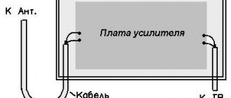
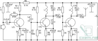
There is no error in this diagram. Below at the end is a diagram without abbreviations, such as “Grounding”, although people are not accustomed to looking at drawn wires intertwined with each other. You will still have to solder the "surface mount". We connect the anode of the lamp through headphones to the plus of the capacitor, which has 200 volts. On headphones at 32 Ohms, the voltage drops to 0.4 Volts, but the current remains 9mA. With such low voltage and low current, the headphones do not burn or heat up. It’s even better to connect high-impedance 50ohm or 70ohm headphones.
At voltages from 12 to 100 volts, the lamps sound the same and are not colorful. Any lamp: 6n6p, 6n2p, 6n23p, 6n8s, 6s3p, 6s19p has not yet given 200 volts - the sound is not the same. I was afraid of burning my headphones with high voltage, but everything works and I listened for several days with 32 ohm headphones. At different volumes, all frequencies are the same - and the bass does not disappear, the high frequencies do not scream, and the mids are not hidden or stick out.
In circuits where the anode is loaded onto a resistor and then transferred through the electrolyte to the headphones, all the power goes to the resistor, leaving the headphones with screaming high and mid frequencies and weak low frequencies. The sound is also distorted by the electrolyte.
And the transformer is the biggest distortion. This option does not work for headphones.
Here all the power goes to the headphones. Nothing spoils the frequency response of beautiful music - not the output transformer, not the electrolyte capacitor, not the anode resistor, which cancels half of the spectrum.
This circuit may seem confusing due to the fixed offset. Fixed bias is a variable resistor with a capacitor, look closely, nothing complicated. Correct power distribution and correct connection of the input signal eliminates the background completely, and the capacitor capacity of 470 microfarads helps to cover all the imperfections with the background. Instead of reading forums, shielding wires, installing kenotrons and chokes in the power supply, figure out this circuit. It is not necessary to ground and connect the negative to the amplifier case, shield the transformer and twist the filament wires into a twisted pair or take the middle point from the filament to the ground.
The bias for the lamp is taken from the 6.3 volt filament winding, rectified and adjusted by a voltage divider minus 2 volts. A 10 kilo-ohm variable resistor acts as a divider. The ends of the resistor from plus to minus of the capacitor are soldered directly, and the middle terminal of the resistor goes to the lamp grid through 470 kilo-ohms. The capacitor responsible for the bias is connected plus or minus the capacitor that powers the lamp anode. Measure the grid voltage between the cathode and the grid. (pins 8 and 5)
The complete circuit is mono. This shows the correct power, input and load connections. The first capacitor (closer to the diode bridge) is common to the two channels; two 500 ohm 1 W resistors go from it to the 470 μF 400 V anode capacitors.
Consider the power supply scheme
All shock currents from the diode bridge are absorbed by capacitor C1.
The ripple filter R1 smoothly transfers current to capacitor C2 without passing shock currents. This is a technique against the network background.
The power supply for the stereo circuit is shown in the figure below.
The power transformer must have a winding voltage of: 6.3V not less than 0.6A 140V not less than 70mA (after rectification it will be 190 volts)
List of radioelements
| Designation | Type | Denomination | Quantity | Note | Shop | My notepad |
| Scheme 1. | ||||||
| Radio tube | 1 | Search in the Otron store | To notepad | |||
| Capacitor | 1 | Search in the Otron store | To notepad | |||
| Electrolytic capacitor | 1 | Search in the Otron store | To notepad | |||
| Resistor | 1 | Search in the Otron store | To notepad | |||
| Speaker | 1 | Search in the Otron store | To notepad | |||
| power unit | 200 V | 1 | Search in the Otron store | To notepad | ||
| Scheme 2. | ||||||
| Radio tube | 1 | Search in the Otron store | To notepad | |||
| Capacitor | 2 | Search in the Otron store | To notepad | |||
| Electrolytic capacitor | 1 | Search in the Otron store | To notepad | |||
| Resistor | 2 | Search in the Otron store | To notepad | |||
| Speaker | 1 | Search in the Otron store | To notepad | |||
| power unit | 200 V | 1 | Search in the Otron store | To notepad | ||
| Scheme 3. | ||||||
| Radio tube | 1 | Search in the Otron store | To notepad | |||
| Capacitor | 1 | Search in the Otron store | To notepad | |||
| Electrolytic capacitor | 1 | Search in the Otron store | To notepad | |||
| Resistor | 2 | Search in the Otron store | To notepad | |||
| Speaker | 1 | Search in the Otron store | To notepad | |||
| power unit | 200 V | 1 | Search in the Otron store | To notepad | ||
| Scheme 4. | ||||||
| Radio tube | 1 | Search in the Otron store | To notepad | |||
| Capacitor | 1 | Search in the Otron store | To notepad | |||
| Electrolytic capacitor | 2 | Search in the Otron store | To notepad | |||
| Resistor | 1 | Search in the Otron store | To notepad | |||
| Variable resistor | 1 | Search in the Otron store | To notepad | |||
| Speaker | 1 | Search in the Otron store | To notepad | |||
| Scheme 5. | ||||||
| Radio tube | 1 | Search in the Otron store | To notepad | |||
| Capacitor | 2.2 µF | 1 | Search in the Otron store | To notepad | ||
| Electrolytic capacitor | 470 µF | 1 | Search in the Otron store | To notepad | ||
| Electrolytic capacitor | 470 µF 400 V | 2 | Search in the Otron store | To notepad | ||
| Resistor | 500 Ohm | 1 | 1 W | Search in the Otron store | To notepad | |
| Variable resistor | 10 kOhm | 1 | Search in the Otron store | To notepad | ||
| Variable resistor | 100 kOhm | 1 | Search in the Otron store | To notepad | ||
| Resistor | 470 kOhm | 1 | Search in the Otron store | To notepad | ||
| Speaker | 1 | Search in the Otron store | To notepad | |||
| power unit | 200 V, 8 V | 1 | Search in the Otron store | To notepad | ||
| Scheme 6. | ||||||
| Radio tube | EF95 | 2 | Search in the Otron store | To notepad | ||
| Electrolytic capacitor | 10 µF | 2 | Search in the Otron store | To notepad | ||
| Resistor | 10 kOhm | 2 | Search in the Otron store | To notepad | ||
| Telephone | 2 | Search in the Otron store | To notepad | |||
| L, R | Input connector | 2 | Search in the Otron store | To notepad | ||
| power unit | 12 V | 1 | Search in the Otron store | To notepad | ||
| Scheme 7. | ||||||
| VL1 | Radio tube | 6N6P | 1 | Search in the Otron store | To notepad | |
| C1 | Capacitor | 4.7 µF | 1 | Search in the Otron store | To notepad | |
| C2 | Capacitor | 4700 µF | 1 | Search in the Otron store | To notepad | |
| C3 | Capacitor | 470 µF | 1 | Search in the Otron store | To notepad | |
| R1 | Resistor | 22 kOhm | 1 | Search in the Otron store | To notepad | |
| R2 | Resistor | 86 Ohm | 1 | Search in the Otron store | To notepad | |
| R3 | Resistor | 3.6 kOhm | 1 | Search in the Otron store | To notepad | |
| Rn | Load resistance | 3G | 1 | Search in the Otron store | To notepad | |
| G1 | Audio source | 1 | Search in the Otron store | To notepad | ||
| E1 | Battery | 220 V | 1 | Search in the Otron store | To notepad | |
| Scheme 8. | ||||||
| Radio tube | 5687WB | 1 | Search in the Otron store | To notepad | ||
| Electrolytic capacitor | 100 µF | 4 | Search in the Otron store | To notepad | ||
| Resistor | 110 Ohm | 2 | Search in the Otron store | To notepad | ||
| Resistor | 3.6 kOhm | 2 | Search in the Otron store | To notepad | ||
| power unit | 12 V | 1 | Search in the Otron store | To notepad | ||
| Scheme 9. | ||||||
| V1, V2 | Radio tube | 6ZH1P | 2 | Search in the Otron store | To notepad | |
| C1 | Electrolytic capacitor | 10 µF | 1 | Search in the Otron store | To notepad | |
| C2, C6 | Capacitor | 0.022 µF | 2 | Search in the Otron store | To notepad | |
| C3 | Capacitor | 0.1 µF | 1 | Search in the Otron store | To notepad | |
| C4 | Electrolytic capacitor | 20 µF | 1 | Search in the Otron store | To notepad | |
| C5 | Capacitor | 1 µF | 1 | Search in the Otron store | To notepad | |
| R1 | Resistor | 240 kOhm | 1 | Search in the Otron store | To notepad | |
| R2 | Resistor | 560 Ohm | 1 | Search in the Otron store | To notepad | |
| R3 | Resistor | 470 kOhm | 1 | Search in the Otron store | To notepad | |
| R4 | Resistor | 3 MOhm | 1 | Search in the Otron store | To notepad | |
| R5 | Variable resistor | 500 kOhm | 1 | Search in the Otron store | To notepad | |
| R6 | Resistor | 1.5 kOhm | 1 | Search in the Otron store | To notepad | |
| Tr1 | Output transformer | 1 | Search in the Otron store | To notepad | ||
| Ls1 | Speaker | 1 | Search in the Otron store | To notepad | ||
| power unit | 125 V | 1 | Search in the Otron store | To notepad | ||
| Scheme 10. | ||||||
| Radio tube | 1 | Search in the Otron store | To notepad | |||
| Diode | 8 | Search in the Otron store | To notepad | |||
| Capacitor | 1 | Search in the Otron store | To notepad | |||
| Electrolytic capacitor | 3 | Search in the Otron store | To notepad | |||
| Resistor | 2 | Search in the Otron store | To notepad | |||
| Variable resistor | 2 | Search in the Otron store | To notepad | |||
| Speaker | 1 | Search in the Otron store | To notepad | |||
| Transformer | 140 V, 6.3 V | 1 | Search in the Otron store | To notepad | ||
| Scheme 11. | ||||||
| Radio tube | 6С2С | 1 | Search in the Otron store | To notepad | ||
| Diode | 8 | Search in the Otron store | To notepad | |||
| Capacitor | 2.2 µF | 1 | Search in the Otron store | To notepad | ||
| Electrolytic capacitor | 470 µF 25 V | 1 | Search in the Otron store | To notepad | ||
| Electrolytic capacitor | 470 µF 400 V | 2 | Search in the Otron store | To notepad | ||
| Resistor | 500 Ohm | 1 | 1 W | Search in the Otron store | To notepad | |
| Variable resistor | 10 kOhm - 50 kOhm | 1 | Search in the Otron store | To notepad | ||
| Variable resistor | 100 kOhm | 1 | Search in the Otron store | To notepad | ||
| Resistor | 470 kOhm | 1 | Search in the Otron store | To notepad | ||
| Terminal clamp | 2 | Search in the Otron store | To notepad | |||
| Speaker | 1 | Search in the Otron store | To notepad | |||
| Transformer | 140 V. 6.3 V | 1 | Search in the Otron store | To notepad | ||
| Scheme 12. | ||||||
| Radio tube | 1 | Search in the Otron store | To notepad | |||
| Diode | 4 | Search in the Otron store | To notepad | |||
| C1, C2 | Capacitor | 2 | Search in the Otron store | To notepad | ||
| R1 | Resistor | 1 | Search in the Otron store | To notepad | ||
| Speaker | 1 | Search in the Otron store | To notepad | |||
| Scheme 13. | ||||||
| Radio tube | 2 | Search in the Otron store | To notepad | |||
| Capacitor | 2.2 µF | 2 | Search in the Otron store | To notepad | ||
| Electrolytic capacitor | 470 µF | 1 | Search in the Otron store | To notepad | ||
| Electrolytic capacitor | 470 µF 400 V | 3 | Search in the Otron store | To notepad | ||
| Resistor | 500 Ohm | 2 | 1 W | Search in the Otron store | To notepad | |
| Variable resistor | 100 kOhm | 2 | Search in the Otron store | To notepad | ||
| Resistor | 470 kOhm | 2 | Search in the Otron store | To notepad | ||
| Variable resistor | 1 | Search in the Otron store | To notepad | |||
| Speaker | 2 | Search in the Otron store | To notepad | |||
| power unit | 200 V, 8 V | 1 | Search in the Otron store | To notepad | ||
| Add all | ||||||
Tags:
- ULF
Let's finalize the scheme
The diagram presented in the document is somewhat incomplete. For normal operation, the circuit should be supplemented with input circuits.
Operational amplifiers are equally good at amplifying both AC and DC voltages. Therefore, despite all sorts of audiophile troubles, it is considered good form to add a capacitor to the input.
In addition to the capacitor that cuts off the DC voltage, you should add a resistor going to ground. Such a resistor will ensure that the non-inverting input of the op-amp is tied to ground. On the other side. together with the capacitor it forms an RC differentiating circuit.
The resulting RC circuit (R5, C1) will cut off both DC voltage and infra-low frequencies. They do not carry useful information, but they significantly load the amplifier with current. At the ratings indicated in the diagram, the cutoff frequency is 16 Hz. When using a 220nF capacitor, the cutoff frequency will drop to approximately 7Hz. Further increase in capacity does not make much sense.
To exclude possible self-excitation of the op-amp, it would not be amiss to limit the upper range. To do this, install a small capacitor in parallel with R2.
Circuit R2 C2 will act as a low pass filter. With the specified part ratings, the cutoff frequency will be about 100 kHz.
Power filter circuit
Here is the filter diagram. Diode - any silicon; instead of the IRFP240 field switch, you can use IRFP450 or similar; those used in the amplifier are also suitable. This is a classic transistor filter whose circuit is part of the ZEN V9 Nelson Pass amplifier.
In principle, 1 x 4700 µF before and 2 x 2200 µF after filters is enough; ideally, instead of 1 x 2200 µF, give 2 x 1000 µF with low ESR. Class A amplifiers draw almost constant current, there is no power fluctuation in music as with other classes of amplifiers, hence there is much less need for large capacitors in the power supply. The presented circuit is correct and soldered without errors should work immediately.