Today we have a useful homemade product for connoisseurs of good sound: a high-quality tube amplifier made by yourself
Hello!
I decided to assemble a push-pull tube amplifier (my hands were really itching) from the parts I had accumulated over a long time: housing, lamps, sockets for them, transformers, etc.
I must say that I got all this stuff for nothing (free of charge), and the cost of my new project will be 0.00 hryvnia, and if I need to buy something in addition, I’ll buy it for rubles (since I started my project in Ukraine, and I’ll finish already in Russia).
I'll start the description with the body.
Once upon a time it was, apparently, a good amplifier from SANYO model DCA 411.
But I didn’t have a chance to listen to it because I got it in a terribly dirty and non-working state, it was dug up beyond repair and the burnt 110 V power supply (Japanese, probably) smoked all the insides. Instead of the original final stage microcircuits, there are some snot from Soviet transistors (this is a photo from the Internet of a good example). In short, I gutted it all out and began to think. So, I couldn’t think of anything better than stuffing a lamp there (there’s quite a lot of space there).
Decision is made . Now we need to decide on the scheme and details. I have a sufficient number of 6p3s and 6n9s lamps.
Due to the fact that I had already assembled a single-cycle amplifier for 6p3s, I wanted more power and, having rummaged through the Internet, I chose this push-pull amplifier circuit for 6p3s.
Unique device
Hi-End tube amplifiers are a special class of household appliances. What is this connected with? Firstly, they have some pretty interesting design and architecture. In this model, a person can see everything he needs. This makes the device truly unique. Secondly, the characteristics of a Hi-End tube amplifier differ from alternative models that use transistor integrated circuits. The difference between Hi-End is that a minimum number of parts are used during installation. Also, when evaluating the sound of this device, people trust their ears more than nonlinear distortion measurements and an oscilloscope.
Powerful tube amplifier
This was developed somewhere in the late 80s. During this time, it has proven itself to be worthy and versatile: it is suitable both for lovers of high-quality sound (I composed for myself) and for musicians who need power.
Brief lyrical introduction. At one time, the amplifier published in the Radio magazine in 1972 was very popular. I also repeated this pattern. Its disadvantages are known to many who repeated it: low linearity, weak stability at low frequency, insufficient stability at high frequency (which is why a corrective air conditioner was introduced into the circuit), a narrow frequency range, and something else that I don’t remember now. And most importantly, the sound left much to be desired.
I couldn’t stand this at home: my ears are not official :) The first thing I started the modernization with was replacing the output trance. The changes made to the output trance suggested themselves - to tighten the connection of the feedback windings (ultralinear) with the rest of the windings, to reduce Kg at higher frequencies, and to improve the frequency and phase characteristics of the output stage. In the version that I used in the new design, it was possible to expand the frequency range, increase HF stability, and lower the output impedance. The sound has improved noticeably, but now the entire circuit design (a clone of the so-called “Williamson circuit”) began to seem far-fetched in Hi-Fi - it was done somehow “head-on”, the weak link remained weak stability with OOS at infra-low frequencies, increased nonlinear and frequency distortions (especially at HF).
Further improvement resulted in the complete abandonment of this scheme. Many different circuit solutions were tried. Attempts to find the best option led to the solution that I propose. At the input, I used a cascode UA with high linearity, then a phase-inverted cascade with a divided load, which has the highest linearity. At the same time, I connected them directly to reduce phase shifts along the signal path. At the output, however, the familiar ultra-linear output stage remained with minor changes (for the purpose of ease of setup and increased stability), and, as already mentioned, with an improved output trance. In the diagram, I conventionally divided the preliminary stages, a bunch of triodes in which is actually my know-how ;), and the output stage, instead of which you can connect any suitable one. With a properly manufactured and adjusted amplifier, the maximum amplitudes on the control grids of the output lamps should be at least 80V at a load of 47k. And this made it possible to fully pump up the 6P45S. And what’s important is that, for all its advantages, the scheme turned out to be even simpler than the one we had to abandon.
The result is an amplifier with a sound that (with proper measures) can easily qualify for hi-end. The amplifier is absolutely stable, so it can be used both with deep OOS and without it at all - the linearity of all stages ensures low distortion even with an open loop OOC.
From two 6P3S, I managed to get >150 watts, from two 6P45S - >220 ;), and in the version with grid currents (especially for musicians) - 400 watts of peak power! But that diagram is already noticeably different from the one given.
I can’t give detailed parameters of the amplifier now - I haven’t measured it for a long time. For those who need sound and not parameters, I have given enough information for repetition, and if it is really necessary, I can (albeit at great cost) re-measure them. I would probably try it on for a magazine. And here it will do :o)
As for setup, it is simple:
- assemble a standard parameter measurement scheme;
- disable OOS;
- turn on the power and warm up the cathodes;
- resistors R10 and R11 set the quiescent currents of the output. lamps 30...60mA (0.06...0.12V at the cathodes), but always identical;
- without supplying a signal to the input, use the R2 regulator to set the cathode of the bass reflex to 105V;
- apply a signal to the input until the load voltage reaches 15 volts (for a 6-ohm variant);
- resistor R9 sets the minimum of the 2nd harmonic at the output;
- restore OOS (optional).
Point 7 can be skipped if you replace R8 and R9 with one with a resistance of 12k (this may not even affect the quality in any way, especially with OOS).
To power the amplifier, additional voltages were needed: 410V (10mA/channel) and stabilized 68V (b/t). The diagram shows one of the options for obtaining them from the available ones. Here you can do it in different ways. For example, I have a stub source. +220V to power the preamplifier, so I got +68 as a divider.
At one time, the scheme was shrouded in trade secrets :). Now please - let anyone who wants to try it. I repeat that the UN-FI combination is universal and can be used to drive various PP output stages (triode, pentode, class A, AB). For each specific case, you may have to recalculate some elements, which is done very easily. This is how I can help those in need.
PS: “Priboy” amplifiers lend themselves well to such modifications – the quality improves noticeably.
List of radioelements
| Designation | Type | Denomination | Quantity | Note | Shop | My notepad |
| Radio lamp | 6N1P | 2 | Search in the Otron store | To notepad | ||
| Radio lamp | 6P45S | 2 | Search in the Otron store | To notepad | ||
| C1, C5, C6 | Capacitor | 1 µF | 3 | Search in the Otron store | To notepad | |
| C2 | Electrolytic capacitor | 47 µF | 1 | Search in the Otron store | To notepad | |
| C3 | Capacitor | 0.1 µF | 1 | Search in the Otron store | To notepad | |
| C4 | Capacitor | 0.047 µF | 1 | Search in the Otron store | To notepad | |
| R1 | Resistor | 220 kOhm | 1 | 0.5 W | Search in the Otron store | To notepad |
| R2, R9 | Trimmer resistor. | 4.7 kOhm | 2 | Search in the Otron store | To notepad | |
| R3 | Resistor | 100 Ohm | 1 | 0.5 W | Search in the Otron store | To notepad |
| R3 | Resistor | 100 kOhm | 1 | 2 W. By mistake in the circuit two resistors are named as R3 | Search in the Otron store | To notepad |
| R4 | Resistor | 2 MOhm | 1 | 0.5 W | Search in the Otron store | To notepad |
| R6 | Resistor | 1 MOhm | 1 | 0.5 W | Search in the Otron store | To notepad |
| R7 | Resistor | 12 kOhm | 1 | 2 W | Search in the Otron store | To notepad |
| R8 | Resistor | 10 kOhm | 1 | 0.5 W | Search in the Otron store | To notepad |
| R10, R11 | Trimmer resistor | 22 kOhm | 2 | Search in the Otron store | To notepad | |
| R12, R13 | Resistor | 47 kOhm | 2 | 0.5 W | Search in the Otron store | To notepad |
| R14, R15 | Resistor | 1 kOhm | 2 | 0.5 W | Search in the Otron store | To notepad |
| R16, R17 | Resistor | 22 kOhm | 2 | 1 W | Search in the Otron store | To notepad |
| R18, R19 | Resistor | 2 ohm | 2 | 2 W | Search in the Otron store | To notepad |
| R20 | Resistor | 2.7 kOhm | 1 | 1 W | Search in the Otron store | To notepad |
| R21, R22 | Resistor | 68 Ohm | 2 | 2 W | Search in the Otron store | To notepad |
| Discharger | 1 | Search in the Otron store | To notepad | |||
| Output transformer | 1 | Search in the Otron store | To notepad | |||
| The given version of the power circuits. | ||||||
| Zener diode | KS568V | 1 | Search in the Otron store | To notepad | ||
| Zener diode | KS680A | 1 | Search in the Otron store | To notepad | ||
| C1 | Electrolytic capacitor | 50 µF 450 V | 1 | Search in the Otron store | To notepad | |
| C2 | Electrolytic capacitor | 100 µF 80 V | 1 | Search in the Otron store | To notepad | |
| Resistor | 12 kOhm | 1 | 2 W. For stereo version 5.6 kOhm 4 W | Search in the Otron store | To notepad | |
| Resistor | 47 kOhm | 1 | 2 W | Search in the Otron store | To notepad | |
| Add all | ||||||
Tags:
- ULF
Selecting circuits for assembly
The preamplifier is quite simple to assemble. For it, you can choose any suitable scheme and start assembling. Another case is the output stage, that is, a power amplifier. As a rule, many different questions arise with it. The output stage has several types of assembly and operating modes.
The first type is a single-cycle model, which is considered a standard cascade. When operating in “A” mode, it has slight nonlinear distortion, but, unfortunately, has rather poor efficiency. Also noteworthy is the average power output. If you need to fully sound a fairly large room, you will need to use a push-pull power amplifier. This model can operate in “AB” mode.
In a single-ended circuit, only two parts are enough for the device to work well: a power amplifier and a pre-amplifier. The push-pull model already uses a phase inverted amplifier or driver.
Of course, for two types of output stage, in order to work comfortably with an acoustic system, it is necessary to match the high interelectrode resistance and the low resistance of the device itself. This can be done using a transformer.
If you are a connoisseur of “tube” sound, then you should understand that you need to use a rectifier, which is produced on a kenotron, to achieve such a sound. In this case, semiconductor parts cannot be used.
When developing a Hi-End tube amplifier, you don't have to use complex circuits. If you need to sound a fairly small room, then you can use a simple single-cycle design, which is easier to make and configure.
PP Push-Pull Tube Amplifiers PP is short for Push-Pull.
- 2.5W. Class B triode amplifier using 6N6P, 6N2P tubes.
- 3.5W. Tube amplifier for 6N6P, 6F1P.
- 7.5W. Push-pull amplifier based on a 6N9S tube.
- 6W. A simple push-pull tube amplifier for 6P14P.
- 6W. Push-pull class A amplifier using 6P6S tubes.
- 10W. Push-pull amplifier on 6F3P.
- 12W. Tube ULF with ultra-linear final stage on 6P14P.
- 12W. Ultralinear tube amplifier for 6P14P, 6N2P.
- 15W. Push-pull ULF on 6P3S, EL34.
- 16W. Miniature ULF on 6P36S.
- 20W. Push-pull tube amplifier based on 6P36S.
- 20W. Push-pull amplifier based on 6P36S and 6N1P tubes.
- 22W. Ultralinear push-pull amplifier based on 6P3S and 6N8P tubes.
- 25W. Push-pull tube amplifier on GU-50
- 80W. Ultralinear push-pull ULF on four 6P3S and 6N8P lamps.
- 200…400W. Powerful push-pull amplifier using 6P3S or 6P45S tubes.
- Push-pull amplifier on 6С4С.
- Entry-level push-pull tube amplifier for 6P18P, 6P43P
- Push-pull ULF channel on 6P45S lamps
- Ultralinear amplifier for 6P14P, 6N1P with microphone input.
DIY Hi-End tube amplifier
Before starting installation, you need to understand some rules for assembling this type of device. We will need to apply the basic principle of installing lamp devices - minimizing fasteners. What does it mean? You will need to discard the mounting wires. Of course, this cannot be done everywhere, but their number must be minimized.
A good Hi-End tube amplifier uses mounting tabs and strips. They are used as additional points. This type of assembly is called hinged. You will also need to solder the resistors and capacitors that are on the lamp panels. It is highly not recommended to use printed circuit boards and assemble conductors so as to create parallel lines. This will make the assembly look chaotic.
Amplifier and power supply circuit board
The entire amplifier was made on a printed circuit board. Of course there are many proponents of surface-mounted components in tube amplifiers, but the advantages of using a printed circuit board include repeatability, especially when the VLF is built by less experienced people, and clean connections. During the design of a printed circuit board, much attention is paid to the operation of grounding, power circuits and maintaining the required distance between lines with different potentials.
In addition to the main amplifier board, two smaller ones were developed. One of them has a headphone jack, the other a volume control potentiometer and additional potentiometers to introduce attenuation if you need to reduce the sensitivity of the amplifier. The elements included in each board were outlined with dotted lines on the diagram. The amplifier board was designed in such a way that resistors with a power of at least 0.5 W could be installed on it. The diagram also shows approximate voltage values at individual points in the circuit.
Removing Interference
Later, you need to eliminate the low-frequency background, if, of course, it is present. Another important point is the choice of grounding point. In this case, you can use one of the options:
- The type of connection is a star, in which all “ground” conductors are connected to one point.
- The second method is to lay a thick copper busbar. It is necessary to solder the corresponding elements onto it.
In general, it is better to find a grounding point yourself. This can be done by determining the level of low-frequency background by ear. To do this, you need to gradually close all the grids of lamps that are located on the ground. If, when the subsequent contact is closed, the low-frequency background level decreases, then you have found a suitable lamp. To achieve the desired result, it is necessary to experimentally eliminate unwanted frequencies. You should also apply the following measures to improve the quality of your build:
- To make filament circuits for radio tubes, you need to use twisted wire.
- Tubes used in the preamplifier must be covered with grounded caps.
- It is also necessary to ground the housings with variable resistors.
If you want to power the preamp tubes, you can use DC current. Unfortunately, this requires connecting an additional unit. The rectifier will violate the standards of a Hi-End tube amplifier, since it is a semiconductor device that we will not use.
Story
Tubes, like other electronic components, have a rich history that has seen significant evolution. It all started in the 2000s of the last century, and the end of the tube era can be considered the sixties, when the last fundamental development saw the light of day - miniature radio tubes, Nuvistors, and transistors had already begun to actively conquer the market. But from the whole history we are interested only in the key stages when the main types of radio tubes were created and the basic circuits for their inclusion were developed.
The world's first triode by inventor Lee de Forest, 1908
The first type of radio tubes developed to create amplifiers were triodes. The number 3 is heard in the name for a reason - this is exactly how many active outputs the triode has. The operating principle of a triode is extremely simple. Between the anode and cathode of the lamp, the power source and the primary winding of the output transformer (to the secondary winding of which the acoustics are connected) are connected in series. The useful signal is supplied to the lamp grid. When voltage is applied to the amplifier circuit, a flow of electrons flows between the cathode and anode, and the grid located between them modulates this flow according to changes in the level of the incoming signal.
As triodes were used in various industries, it was necessary to improve their characteristics. One of these characteristics was the pass-through capacitance, the value of which limited the maximum operating frequency of the lamp. In the process of solving this problem, tetrodes appeared - radio tubes with not three, but four electrodes inside. The fourth was a screening grid installed between the control grid and the anode. This solved the problem of increasing the operating frequency to the fullest extent, which completely satisfied the creators of the technology, who developed tetrodes so that radio stations and radio receivers could operate in the short-wave range, which has higher carrier frequencies than the medium- and long-wave ones.
Triode structure
From the point of view of sound reproduction quality, the tetrode did not fundamentally surpass the triode, so another group of scientists, puzzled by the issues of reproduction of sound frequencies, improved the tetrode, using essentially the same approach - simply adding another additional grid to the lamp design, located between the shielding grid and anode. This was necessary in order to suppress the dynatron effect - the reverse emission of electrons from the anode to the shielding grid. Connecting an additional grid to the cathode prevented this process, making the lamp's output characteristic more linear and increasing power output. Thus a new type of lamp appeared: the pentode.
Transformers
Another important point is the use of different transformers. As a rule, power and output are used, which must be connected perpendicularly. This way you can reduce the level of low-frequency background. Transformers should be located in grounded enclosures. It must be remembered that the cores of each transformer should also be grounded. There is no need to use shielded wire when installing devices to avoid additional problems. Of course, these are not all the features associated with installation. There are quite a lot of them, and it will not be possible to consider them all. When installing a Hi-End (tube amplifier), you cannot use new element bases. They are now used to connect transistors and integrated circuits. But in our case they will not work.
Resistors
A high-quality Hi-End tube amplifier is a retro device. Of course, the parts for its assembly must be appropriate. Instead of a resistor, a carbon and wire element may be suitable. If you spare no expense in developing this device, you should use precision resistors, which are quite expensive. Otherwise, MLT models are applicable. This is a pretty good element, as evidenced by the reviews.
Hi-End tube amplifiers are also suitable for use with BC resistors. They were made about 65 years ago. Finding such an element is quite simple; you just need to walk around the radio market. If you are using a resistor with a power of more than 4 Watts, you need to choose enameled wire elements.
Capacitors
In a tube amplifier setup, you should use different types of capacitors for the system itself and the power supply. They are usually used to adjust the tone. If you want to get high-quality and natural sound, you should use a coupling capacitor. In this case, a small leakage current appears, which allows you to change the operating point of the lamp.
This type of capacitor is connected to the anode circuit, through which a large voltage flows. In this case, it is necessary to connect a capacitor that maintains a voltage greater than 350 volts. If you want to use quality parts, you need to use parts from Jensen. They differ from analogues in that their price exceeds 3,000 rubles, and the price of the highest quality radio elements reaches 10,000 rubles. If you use domestic elements, it is better to choose between the K73-16 and K40U-9 models.
Making a housing for a power amplifier with your own hands
Today we'll talk about how you can make a housing for your DIY power amplifier project. A beautiful and neat body is the face of any project. They greet you by their clothes! The body is a known headache for DIYers. Let's look at some methods for building a do-it-yourself audio power amplifier housing.
Content
- From old equipment
- Sheet metal
- Sheet metal with flexible
- Plywood
- Enclosures for electronic equipment
- Purchased
From old equipment
In particular: VCRs, satellite receivers, DVD players, etc. What was on hand (in the closet) and approximately fits in size. Convenient because the box is already there. We throw away the “offal”, although you can leave low-current power for auxiliary consumers. The appearance of the case can be refreshed with paint or vinyl film. The front and back panels can be cut from metal or plastic, for example by an advertising agency or metal cutting organization. And put it in the trim on the existing case.
The housings of Soviet amplifiers should not be excluded from attention. They used excessively thick metal. For example, you can place a powerful amplifier in the Odyssey U-010 case, which I once did, and put my front panel on top of the old one with screws.
What can I say, I managed to make small amplifiers in CD-rom cases (which have long since been consigned to the dustbin of history). With proper attention it turns out quite well.
Sheet metal
The idea of making a body from sheet parts is on the surface.
Now almost every city has laser or waterjet cutting services for sheet metal. We cut the walls and body sheets to the required size and assemble the box.
The main constructive question in this case is how to connect the sheets together. To connect the body sheets into a box you can use:
- Corners
- Purchased radiators with holes
- Milled racks
- Wooden sides with driven nuts
- Profiles
Let's go through each option.
Before starting work on the body, having the required internal dimensions in mind, you definitely need a sketch/drawing/three-dimensional model of the future body, so as not to make a mistake in the dimensions.
Corners
The frame is assembled from aluminum corners and sheathed with body sheets. It’s quite easy and affordable to do it yourself - there are many examples on the Internet.
Radiators
There are radiator profiles on sale that have threaded holes on all sides. For example 246*84*25 mm with holes.
Assembling the case - the base is radiators, all sheet panels are screwed to them.
In this case, the sheets were made of carbon steel, and were painted with powder paint, which, as it turned out, looks great, is scratch-resistant and is not at all expensive.
Milled racks
Available if you have machines: turning and milling. I made a cylinder from aluminum with a quarter recess (angle 90 degrees), there were threaded holes cut for fastening sheets inside the body.
This housing is assembled in the title picture of the topic. It is assembled from stainless steel sheets, chemically cleaned, sanded and coated with matte varnish.
Wooden sides
It is both beautiful and can be used not only for decorative purposes, but also as a load-bearing part of the body. For wood on the sides, you can use cutting boards (beech, oak). They are quite smooth and look good under varnish. Drive-in nuts or furniture threaded fittings can be used to hold the body panels in place.
Profiles
Construction stores in large cities now offer a large selection of aluminum profiles of various shapes.
The side walls of the housing can also be profiles (channels):
And this DIY case is a combination of three methods:
- Front and rear panels - aluminum profile (channel)
- Wooden sides (beech, cutting board) ensure assembly
- Sheet top and bottom panel of the case
The manufacturing process of such a case can be seen in the video:
Sheet metal with flexible
Available to those who work in factories or, again, for money. There is a subtlety: you need to be able to design sheet metal products in 3D or use someone else’s models.
I made a DIY clone of an interesting Chinese amplifier (P01) from two flexible parts. His review is here.
My clone of the Chinese case looks a little more brutal:
By the way, inside there is an ICE125ASX2 from ICEpower® and volume control and an input selector on the PGA2311.
Bending can be simpler - with one bend, to which the body sheets are mounted:
Plywood
An option for cabinetmakers and simply for those who are comfortable with a jigsaw and a hand router.
Sheets of plywood placed crosswise look unusual under varnish. The front and back panels are aluminum. Such a case, of course, is for an amplifier that does not require good convective cooling, for example, for high-efficiency class D amplifiers.
Enclosures for electronic equipment
There are interesting composite options - metal and plastic. Radio stores in your city may have a suitable option.
For a solid look to the case, again, you can put your front panel in an overlay.
Purchased
And, of course, an online purchase option. When the hands, of course, are golden, but do not grow from the shoulders. But at least you pay for the order with your own hands.
I made a selection of interesting housing options for diy projects from Aliexpress:
Selection of cases from Aliexpress
Thank you for your attention. Creative success and successful designs!
Assembly
Let's start the assembly with the pre-amplifier. Its installation follows a fairly simple scheme. It is also necessary to provide power control and a separator for tone control. It should be tuned to low and high frequencies. To increase shelf life, you need to use a multi-band equalizer.
In the laughter of the preamplifier you can see similarities with the common 6N3P double triode. The element we need can be assembled in a similar way, but use the final cascade. This is also repeated in stereo. Remember that the structure must be assembled on a circuit board. First it needs to be debugged, and then it can be installed on the chassis. If you installed everything correctly, the device should turn on immediately. Next you should move on to configuration. The value of the anode voltage for different types of lamps will differ, so you will need to select it yourself.
Radio tube amplifier circuit
Amplifier and power supply circuit using 6P14P radio tubes
As you can see, this is a typical pentode configuration operating in class A, with element values selected based on datasheet recommendations, so there is no point in describing individual radio elements in the diagram. The switch marked STDBY turns on the anode voltage of the lamps with a delay. Additionally, this switch contains resistor R16, thanks to which, after turning on the power to the amplifier, we limit the surge in the filament current of cold lamps. In addition, resistor R15 introduces filament voltage correction.
Warning: The amplifier contains dangerous high voltage. Always work with caution and if you are not sure about something, you need to seek help from more experienced radio amateurs!
The entire amplifier is covered by a negative feedback loop, which, although it reduces the sensitivity of the amplifier (to approximately 0.5 V rms), but significantly improves its stability.
LUNC output power according to the documentation for EL84: Pa max = 12 W, for 6P14P: Pa max = 14 W. The durability of 6P14P is indicated at a minimum of 3000 working hours, for EL84 about 1000.
A headphone jack has been added. The method is quite primitive, because when switching to headphones, almost all the power is dissipated in resistors R10, which act as an artificial load, but thanks to this, you can connect headphones with any resistance, there is no risk of damage if the headphones are accidentally disconnected when the amplifier is turned on. Resistors R11 were also added to each channel, which provide safety if we accidentally turn off the speakers when the amplifier is turned on.
Components
If you do not want to use a high-quality capacitor, then you can use K73-16. It will be suitable if the operating voltage is more than 350 volts. But the sound quality will be noticeably worse. Electrolytic capacitors are also suitable for this voltage. You need to connect the C1-65 oscilloscope to the amplifier and submit a signal that will pass from the audio frequency generator. During the initial connection, you need to set the input signal to about 10 mV. If you need to know the gain, you will need to use the output voltage. To select the average ratio between low and high frequencies, it is necessary to select the capacitance of the capacitor.
You can see a photo of a Hi-End tube amplifier below. For this model, 2 lamps with an octal base were used. A double triode is connected to the input, which is connected in parallel. The final stage for this model is assembled on a 6P13S beam tetrode. This element has a built-in triode, which allows you to get good sound.
To configure and check the functionality of the assembled device, you must use a multimeter. If you want to get more accurate values, you should use a sound generator with an oscilloscope. When you have taken the appropriate devices, you can proceed to setup. At cathode L1 we indicate a voltage of about 1.4 Volts; this can be done if you use resistor R3. The output lamp current must be specified as 60 mA. To make resistor R8, you need to install a pair of MLT-2 resistors in parallel. You can use other resistors of different types. It should be noted that a rather important component is the isolation capacitor C3. It was not in vain that it was mentioned, since this capacitor has a strong influence on the sound of the device. Therefore, it is better to use a proprietary radio element. Other elements C5 and C6 are film capacitors. They allow you to increase the quality of transmission of various frequencies.
A power supply built on the 5Ts3S kenotron is worth finding. It complies with all the rules for constructing the device. A homemade Hi-End tube power amplifier will have high-quality sound if you find this element. Of course, otherwise it is worth looking for an alternative. In this case you can use 2 diodes.
For a Hi-End tube amplifier, you can use the appropriate transformer, which was used in old tube technology.
Power supply for a homemade tube amplifier.
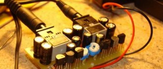
I’ll start the assembly with the power supply and describe it at the same time. The heart of the power supply (and of the entire amplifier, probably) will be the TST-143 toroidal transformer, which I once (4 years ago) tore out of some tube generator right as it was being taken to a landfill. Unfortunately, I didn’t manage to do anything else. It’s a pity for such a generator, but maybe it was still working or could have been repaired... Okay, I digress. Here he is my security officer.
Of course, I found a diagram for it on the Internet.
The rectifier will be on a diode bridge with a filter on the inductor for anode power. And 12 volts to power the backlight and anode voltage delay circuit. This is the throttle I have.
Its inductance was 5 henry (according to the device), which is quite enough for good filtration. And the diode bridge was found like this.
Its name is BR1010. (10 amps 1000 volts). I'm starting to cut out the amplifier. I think it will be something like this.
I mark and cut holes in the PCB for the sockets for the light bulbs.
It's turning out pretty good as long as I like it.
Then I start to figure out how to arrange all the details on this PCB.
This way and that way. drilling sawing
Something began to emerge.
I found a fluoroplastic wire in old supplies and immediately all the alternatives and compromises regarding the wire for installation disappeared without a trace .
This is how the installation turned out. Everything seems to be “kosher”, the incandescence is intertwined, the ground is practically at one point. Should work.
It's time to fence in food. After checking and testing all the output windings of the trans, I soldered all the necessary wires to it and began installing it according to the accepted plan.
As you know, in our difficult amateur radio business, you can’t go anywhere without improvised materials: this is how the Kinder Surprise container came in handy.
And a Nescafe lid and an old CD
Next, I install the rectifier and power filter elements.
I tore out the capacitors from the boards of TVs and monitors. All containers are at least 400 volts (I know that I should have more, but I don’t want to buy them).
I bridge the bridge with containers (whatever were on hand, I’ll probably change them later)
It turns out to be a bit much, but oh well, it will sag under load
I use the standard power switch from the amplifier (clear and soft).
We're done with that. Well done
Backlight for tube amplifier housing.
To implement the backlight, an LED strip was purchased.
And installed in the housing as follows.
Now the glow of the amplifier will be visible during the daytime. To power the backlight, I will make a separate rectifier with a stabilizer on some KRKEN-like microcircuit (which I can find in the trash), from which I plan to power the anode voltage supply delay circuit.
Delay relay.
Having rummaged through the bins of my homeland, I found this completely untouched thing.
This is a radio time relay designer for a photo enlarger.
We collect, check, try on.
I set the response time to about 40 seconds, and replaced the variable resistor with a constant one. The matter is coming to an end. All that remains is to put everything together, install the face, indicators and regulators.
Regulators (input variables)
They say that sound quality can greatly depend on them. In short, I installed these
Dual 100 kOhm. since I have two of them, I decided to parallel the pins, thereby obtaining 50 kOhm and increased resistance to wheezing
Indicators.
I used standard indicators, with standard backlighting
I mercilessly copied the connection diagram from the original board and used it as well.
This is what I ended up with.
When checking the power, the amplifier demonstrated an output voltage of 10 volts of an undistorted sine wave with a frequency of 1000 Hz into a 4 ohm load (25 watts) equally across channels, which was pleasing
When listening, the sound was crystal clear without background and dust, as they say, but too monitory, or what? beautiful, but flat.
I naively believed that he would play without timbres, but...
Using a software equalizer, we managed to get a very beautiful sound that everyone liked. Thank you all very much!!!