It is hardly possible to meet a motorist who has not encountered the problem of a dead battery . In such cases, you cannot do without a reliable power source that uses composite transistors. If you don’t have the necessary device at hand, we’ll tell you how to make a charger from an uninterruptible power supply with your own hands without spending a lot of money. Finding this device is not difficult - it may be a non-working or unnecessary UPS that has long been replaced by a newer model. Why did you choose this product? It's simple - the uninterruptible power supply contains the necessary elements of the electrical circuit. If the UPS is not working, then the most important part for us in it is the transformer.
You can make a charger either from an old and non-working device, or from a working one, if you do not plan to use it further for its main purpose. This operation is relatively simple if you have knowledge related to electronics.
Otherwise, we advise you to familiarize yourself with this issue first.
Safety regulations
Safety precautions in our case are no different from those with other electrical appliances . It is strictly forbidden to disassemble devices connected to the network, as well as to carry out any additional manipulations with them. Do not forget that if a malfunction is detected, electrical equipment must be repaired or replaced as soon as possible.
Also, to assemble the charger, you will need certain knowledge in the field of electronics in order to correctly place certain elements of the circuit.
Inverter from uninterruptible power supply
To convert it into an inverter, we chose the UPS Mustek Power Must 800 USB (board number 098-17615-00-S1), this UPS seemed designed to be converted, especially since a load of 500 W for household purposes is not so small
Converting a UPS for a car battery will be divided into several stages:
- Disabling Green Power
- Installing an active cooling system
- Real tests
Green Power in UPS is some kind of tricky feature that prevents the uninterruptible power supply from working on battery power for a long time. In different devices it manifests itself and is implemented differently, in some it turns off the UPS, which works without load after 5-10 minutes, in other devices Green Power does not allow the UPS to work for more than 25-30 minutes, regardless of its load. Sometimes this function can be disabled using a special resistor, but it happens that the shutdown process is hardwired into the UPS microcontroller, and there is nothing much you can do to help it.
First of all, we open the case and take a photo of its insides for ourselves, this must be done so that in the future there will be no questions about what and where to connect during reassembly.
After that, disconnect all the wires and take out the control board, board number 098-17615-00-S1.
If you take a closer look at the board, you can see that there are tables on it that change the operating modes of the uninterruptible power supply.
We are interested in resistor R15A, which is responsible for the Green Power function. We carefully unsolder the resistor from the board, and for those who like silence, you can still make small manipulations with the buzzer. If you want to completely get rid of the squeaks that the UPS makes, you can unsolder the JP82 jumper or remove the buzzer itself, and for those who want to muffle the sound, just solder in a small 100-300 Ohm resistor instead of this jumper.
The next step will be to install an 80mm fan and minor modifications to the UPS case.
The fan attaches perfectly to the plastic jumpers that are already inside the case.
As you can see, the fan is placed in the center of the case, which makes it possible to blow air not only on the transformer, but also on the transistor radiators located in the upper part of the case.
You can come up with a lot of ways to power the fan in the UPS. But we chose the simplest and easiest to repeat. The fan can be powered from the front panel board, which contains the power button and LEDs. Set the power button to the off position. and use a tester to ring the connector pins, find where the plus and minus from the battery come (for us this is the pin: pin 7 is plus, 5 is minus). Already along the track or using a tester, we trace the plus of the battery to the power button and after the button (it returns through pin 8 to the board). This means that the fan power can be taken from the terminals: 5 – minus; 8 is a plus. With this switch on, the fan will work at full power when the power button is turned on, i.e. both when operating from the network (charging) and when operating from the battery.
The next step will be a minor modification of the body. First of all, we make holes for the flow of fresh air to the fan. If it’s a pity to spoil the front panel, you can make holes in the bottom, the height of the legs will allow a small air flow to pass easily.
I was also a little surprised by the decorative plastic covers, which are perforated for ventilation, but there are no holes in these places in the case itself. This can all be solved with a small drill and drill.
The last step before assembly will be fixing the transformer. When carrying a UPS without a standard battery, the transformer literally walks in its seats; it can easily jump out of them and damage the main board.
Now we connect the wires with terminals, instead of the standard battery. For additional insulation, it is better to wear special silicone caps. The wire for connecting a car battery to the UPS should be taken with a cross-section as large as possible, and the wire itself should be as short as possible.
And so, let's drive a little and test our inverter from an uninterruptible power supply.
As you can see, making an inverter from an uninterruptible power supply is not at all difficult, the time has come for real tests. UPS at idle, current consumption is about 1 A.
We put the laptop on charge, the current consumption rose to 5 A.
The UPS is loaded with a 60 W light bulb, the current consumption is almost 8 A.
By the way, the charging current does not rise above 1 A; as it charges, it gradually decreases.
The charging voltage of this UPS is 13.7 V.
It is not difficult to guess that the more capacious your battery, the longer such an inverter from a UPS will work, but it will also take quite a long time to charge from the network.
These photos and recommendations are given for board 098-17615-00-S1 from UPS Mustek Power Must 800 USB. When remaking other UPSs, it is quite possible that these recommendations will only partially remain relevant because The design and circuits will be different. It is important to familiarize yourself in detail with the labels and tables that are indicated on the board, follow the manufacturer’s recommendations and do not try to conduct experiments without knowledge and skills, because It is possible to damage not only the UPS itself, but also the equipment connected to it. The main thing to remember is that life-threatening voltage is present when the UPS is operating.
Scheme
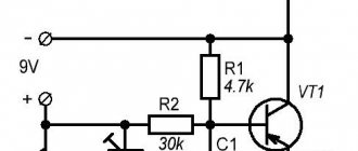
Another option for making a charger yourself. This method differs little from the previous one, but there are diagrams here - this is very convenient for working with electrical devices. Such a device includes powerful composite transistors KT947, KT827. The dotted lines shown in the diagram are additional capacitors. Diodes with transistors can be structurally placed on a common large radiator; insulating gaskets are not required.
If there is no transformer with a 16-volt center tap, you can use a circuit that includes a rectifier bridge. Resistor R1 is needed to protect the composite transistor from short circuits.
If you assemble devices using these circuits, the output voltage will be adjusted from 0 to 15 V, and the maximum charging current will be up to 10 A.
A simple do-it-yourself inverter from an uninterruptible power supply
We all know how unpleasant it is when the lights suddenly go out.
This can happen at any time - at home or in the country. Residents of rural areas cannot be doubly envied, especially if at such moments the incubator or circulation pump is running. A sudden switching off of the lights can lead to the death of the future brood or the stopping of the heating pump. There is an excellent solution to this problem - you just need to buy a car inverter from 12 to 220 V. However, their prices are very high; not every villager can afford to buy such an expensive item.
What to do - where can you inexpensively purchase an uninterruptible power supply for lighting a house, greenhouse, cottage, etc.? Of course, try making it yourself! And the Internet will help us with this.
It turns out that there is a simpler and cheaper solution - you just need to convert the uninterruptible power supply into an inverter.
For this purpose, we will need a working uninterruptible power supply from a computer, which can be bought for literally pennies at flea markets or through advertisements in local newspapers for the sale of used computer equipment. However, the uninterruptible power supply is not entirely suitable for our tasks and requires a little modification. Anyone who knows how to work with a soldering iron can handle this type of work without much difficulty.
How to make a laboratory power supply?
Making a laboratory power supply from an old uninterruptible power supply is a more difficult task. A laboratory power supply is often used by radio amateurs. In addition to the transformer from the old UPS, you will also need :
- powerful transistor;
- diodes for voltage rectification;
- microcircuit (from op-amp);
- relay;
- set of LEDs;
- varistor;
- connectors;
- oxide capacitors;
- ceramic capacitors.
The explanation of the power supply is shown in Figure 2.
The primary winding of the transformer receives voltage from the network through the inserted element FU1 and the power supply switch SA1. RU1 (varistor) connected in parallel serves as protection against voltage surges.
Using R1 (current limiting resistor) and VD1 (diode), the HL1 LED is powered, which acts as an indicator of the presence of mains voltage.
To winding || the voltage rectifier located on VD2-VD5 (diode collections) is connected. The position of the relay contacts K 1.1 determines the operation of the transformer as a full-wave transformer with a voltage of around 10 V or as a bridge with a voltage of approximately 20 V. From the rectifier, the voltage is supplied to the field-effect transistor.
With the help of capacitors C1 and C3, ripples are smoothed out. Using resistor R17, the minimum load of the voltage stabilizer is ensured.
From the rectifier assembled on VD6-VD9 (diodes), with the participation of C2 and C5 (capacitors), the parallel stabilizer is powered to:
- microcircuits (DA1, op-amp DA2);
- relay K1;
- fan M1.
HL2 (LED) emits a signal when there is voltage in this rectifier.
The current limiting threshold is set by resistors :
- R7;
- R8.
The relay (K1) is controlled using a resistor (VT2). The output voltage is set by R19 (trimming resistor). When it is exceeded, the output voltage is switched using a relay. When the maximum temperature value set by R15 (resistor) is exceeded, VT3 (transistor) and RK1 (thermistor) start M1 (fan). Excessive relay and fan voltages are distributed to R13 and R18 (resistors) respectively.
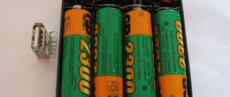
Removing batteries
So, the first thing to do is remove the old, leaking batteries. They can be easily dismantled by removing the bottom cover and disconnecting the power wires. If there are traces of leaked electrolyte, clean the case from oxidation crystals.
This operation will ensure the elimination of further acid leakage and will also significantly lighten the weight of the apparatus.
Communities › Kulibin Club › Blog › Battery charger from an old UPS
It so happened that in winter my car stood outside in the form of a snowdrift for a couple of weeks and its battery died, I didn’t have a charger and I had to quickly get out of the situation. Everything is done very quickly and you just need an old UPS
for aesthetics, you can do everything on the connector so that the cable can be disconnected from the UPS
Here's a budget charger that might come in handy
Comments 93
And if the battery stays on such a charger for a long time, then we get an ideal desulfotator.) Your old AGM 90 a.h. I put it on it to try to make an uninterruptible power supply. I remembered for him a few months later, when in the bitter cold they dropped off a diesel “Vitka” with a completely discharged battery. The box was downhill, there was ice, they couldn’t push it, so they decided to help with the starter. And I was shocked because on my “dead” agm we either pushed the coil into the starter, then started it for another three days)) Since then I have been using these devices to resurrect batteries (of course, if they are not shorted, etc. .) Modern boshes, etc., when they catch a couple of discharges, they quickly sulfate and do not take a charge. Even when new. A month ago, when I arrived at a new job, I saw a toplu top of impressive size (around 100, apparently). It was used as a bench. There are less than 10 on the terminals. In general, with squeaks and screams, but I accepted it as a mustec.)) I have a voltmeter installed so as not to make unnecessary movements. We turn off the electricity in the box at night, so in the morning I check the remaining charge. And in exactly one month, with daily exercises starting from a timid 10.1, in the morning I am already greeted by a pleasant number 12.7)) And I would hang the “boilers” on lamp posts! Because they don’t give a damn about boiling - serviced, unserviced, AGM, gel...
It’s ok for support, but not suitable for full charging - the battery must be charged until it “boils” - Download and read (p. 49):
You can also get 220. A useful thing for the car and garage.
The same uninterruptible device, I also sometimes kill Akum but for 3-5 days, the more it costs the better. And I will say that this is a fact, the most gentle charging is long but high quality, but not for large batteries
Without fish, of course, there is also cancer. You need to measure what it gives at the output, I think there is no more than 13.7, which is quite good for temporary maintenance, but not much like a full charge; you can’t charge it above 70-80%. Well, considering that it most likely does not provide more than 1A, even charging to 70% from 9V will take 3 days. When there is nowhere to rush, this is certainly not bad, but when you need to go faster, it doesn’t work.
A battery that has dropped to 9V is considered deeply discharged. such discharges should be avoided. Not every automatic charger will charge such a battery.
Without fish, of course, there is also cancer. You need to measure what it gives at the output, I think there is no more than 13.7, which is quite good for temporary maintenance, but not much like a full charge; you can’t charge it above 70-80%. Well, considering that it most likely does not provide more than 1A, even charging to 70% from 9V will take 3 days. When there is nowhere to rush, this is certainly not bad, but when you need to go faster, it doesn’t work.
13.9 is the ideal voltage. Used on batteries of solar stations. Eliminates boiling over.
The charging voltage is not 12V, but 15, for some it is 16V. When the required voltage is reached, the current decreases or remains unchanged; does the battery boil at the end of the charge? That there is no faith in such chargers without knowing the characteristics.
Once upon a time, when there was no garage, I used a 220 uninterruptible power supply in a car, and sometimes it helped out a lot. www.drive2.ru/l/466265773896106659/
Also, the charger burned out, the battery went to zero and I had to go, I took a Resant welding machine, connected it to the battery and stood at low current for a while and the starter started turning
For a quick recharge, you can give it 20A. And nothing will happen to the battery. But at the same time, it is strictly important that the charger is able to limit the voltage. 14.4 or 14.7 upper threshold, depends on the type of battery
I once charged it with a Shurik charger for a day, it started up fine)))))
Well, without fish, as they say. And so I have 3 chargers)) Bosch C7, full automatic, Soviet huge transformer up to 63V/12A and small semi-automatic
I burned two