Often, when upgrading a computer, a completely serviceable power supply is left out of use. Its power is not enough to power new components. Those who upgrade hardware may accumulate a lot of such devices. A dilemma arises: to recycle power supplies or find practical use for them. One way to give your computer power supply a second life is to turn it into a lab power supply with adjustable output voltage and adjustable current limiting. You can do this modification yourself.
How to turn on the power supply from a computer without a computer
So, we have in our hands an ATX computer power supply. First of all, let's try to turn it on. But to do this you need to know some of the intricacies of how this device works. Suppose we have a computer in front of us. We plug it into the network, but outwardly nothing happens. This would seem to be clear - the machine is turned off, and to turn it on, you need to press the power button on the front panel of the system unit.
Actually this is not true. As soon as we inserted the plug into the socket, a small part of the circuit in the power supply started working, producing a standby voltage of +5 V. This part is called the standby power module. Voltage is supplied to the motherboard and powers its individual components, one of which is designed to turn on the computer.
Important. Most ATX power supplies have an additional service mechanical switch located on the back of the PC. The mains voltage is supplied to the power supply of these models after turning on this toggle switch.
A mechanical switch is used to supply voltage to this power supply.
By pressing the button on the front panel of the system unit, we thereby send a command to the motherboard (more precisely, its switching unit) to start the power supply. The node sends a Power on signal to the power supply unit, and the power supply unit, and therefore the computer itself, turns on.
Since we don’t have a computer, we will have to send this signal ourselves. This is not difficult to do. To do this, just find the connector on the power supply that powers the motherboard and install a jumper between the green and any of the black wires. So, we install a jumper, connect the power supply to the network, and it starts up immediately - you can hear it even from the noise of the fan.
How to raise 12V line to 13.5V
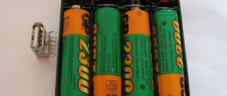
The theory says, and practice flawlessly confirms, that by loading a 5V line with a low-resistance resistor of decent power, the voltage on the 12V line increases. 13.5V on the 12V line occurs only when between the ground wire and the 5V line there is an assembly of 5 series-connected 22Ohm resistors, the total power of which is 50W. If you do not have such resistors, then it is quite possible to load the 5V channel using an assembly of light bulbs connected in series with the corresponding power rating.
Where is 12 volts and where is 5? Understanding color coding
How can you find out which wires produce which voltages? Where, for example, is 12 volts on the computer power supply? You don't need a tester for this, since all the wires coming out of the computer power supply have a strictly defined, generally accepted color. Therefore, instead of a tester, we arm ourselves with the sign below.
Colors and assignment of ATX power supply wires
| Color | Purpose | Note |
| black | GND | wire common minus |
| red | +5 V | main power bus |
| yellow | +12 V | main power bus |
| blue | -12 V | main power bus (may be missing) |
| orange | +3.3 V | main power bus |
| white | -5 V | main power bus |
| violet | +5 VSB | standby food |
| grey | Power good | nutrition is normal |
| green | Power on | command to start power supply |
The plate does not require any special explanation. We got acquainted with the green wire (Power on) in the previous section - the motherboard sends a low-level signal to it (short to common) to turn on the power supply. The blue wire may be missing in new power supply models, since motherboard manufacturers have abandoned the RS-232C interface (COM port), which requires -12 V.
The purple wire (+5 VSB) is just the standby +5 V that powers the standby nodes of the motherboard. Via the gray wire (Power good), the power supply reports that all voltages are normal and the computer can be turned on. If any of the voltages during operation goes beyond the permissible limits or disappears, the signal is removed. Moreover, this happens before the storage capacitors of the power supply have time to discharge, giving the processor time to take emergency measures to stop the system in an emergency. The remaining wires are power wires for the motherboard and peripheral devices - disk drives, external video cards, etc.
Checking functionality and voltage compliance
After this, you should check that the output voltage is correct. To do this, take a known-accurate voltmeter, connect it in parallel with the main one, connect a load (for example, a soldering iron or a 12-36 volt lamp) and begin to smoothly increase the voltage.
If the readings of the device under test are greater, then a 1-10 kOhm variable resistor is soldered in series with 22 kOhm and, by rotating its handle, the voltages are identical. Then measure its resistance and replace it with a part of the same rating.
When the readings are lower, instead of 22 kOhm, a resistor with lower resistance is installed. And they continue to act according to the same principle.
Converting an ATX power supply into a regulated or laboratory power supply
Now is the time to make a switching laboratory power supply from a computer power supply with your own hands. We will be modifying the power supply, the PWM controller of which is assembled on a specialized TL494 microcircuit (aka: μA494, μPC494, M5T494P, KIA494, UTC51494, AZ494AP, KA7500, IR3M02, AZ7500BP, KR1114EU4, MV3759 and similar analogues).
Expert opinion
Alexey Bartosh
Specialist in repair and maintenance of electrical equipment and industrial electronics.
Ask a Question
Let's make a reservation right away - although the typical connection circuits for these microcircuits are the same, there are still some differences depending on the power supply model. Therefore, there is no universal solution for remaking all power supplies.
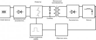
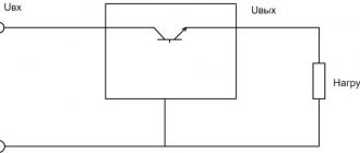
For example, we will modify the power supply, the diagram of which is shown below. Having understood the idea of the changes being made, choosing an algorithm for remaking any other block will not be difficult.
We disassemble the power supply and remove the board. Immediately unsolder all unnecessary wires of the power cables, leaving one yellow, one black and green.
We also solder smoothing electrolytic capacitors along all power lines. In the diagram they are designated as C30, C27, C29, C28, C35. We are going to significantly (up to 25 V on the +12 V bus) increase the output voltage, for which these capacitors are not designed. In place of the one that stood on the +12 V bus, we install a capacitor of the same or larger capacity for a voltage of at least 35 V. We leave the remaining places empty. We solder the green wire in place where any black wire was to allow the power supply to start. Now you can start modifying the controller.
Let's take a look at the pin assignments of the TL494 chip. We are interested in two nodes - error amplifier 1 and error amplifier 2. The first contains a voltage stabilizer, and the second contains a current controller. That is, we are interested in the wiring of pins 1, 2, 3, 4, 13, 14, 15, 16.
Let's change the wiring diagram so that error amplifier 1 is responsible for adjusting the output voltage, and amplifier 2 is responsible for adjusting the current. First of all, we will cut the paths indicated by crosses in the diagram below.
Now we find resistors R17 and R18. The first has a resistance of 2.15 kOhm, the second 27 kOhm. We change them to nominal values of 1.2 kOhm and 47 kOhm, respectively. We add two variable resistors to the circuit, one constant at 10 kOhm (marked in green), terminals for connecting an external consumer, an ammeter and a voltmeter. As a result, we will get a diagram like this.
As can be seen from the diagram, a 22 kOhm resistor allows you to smoothly regulate the voltage within 3-24 V, a 330 Ohm resistor allows the current to vary from 0 to 8 A. Cl1 and Cl2 are used to connect the load. A voltmeter has a measurement limit of 25-30 V, an ammeter - 10 A. The devices can be either pointer or with digital scales, most importantly, small-sized - after all, they must fit into the power supply housing. You can begin checking and calibrating.
Expert opinion
Alexey Bartosh
Specialist in repair and maintenance of electrical equipment and industrial electronics.
Ask a Question
We first turn on our laboratory power supply through a 220 V incandescent lamp with a power of 60 W. This will help avoid problems if we made mistakes in installation. If the lamp does not glow or glows at full intensity, and the power supply starts up, then everything is in order. If the lamp is on at full intensity and the power supply is silent, then you will have to look for errors.
Everything is fine? We connect the power supply directly to the network, and move the resistor sliders to the lowest position according to the diagram. We connect a load to terminals KL1, KL2 - 2 high beam lamps connected in series. We rotate the voltage adjustment resistor and check with the built-in voltmeter that the voltage changes smoothly from 3 to 24 volts. To be sure, we connect a control voltmeter, for example, a tester, to the terminals. We calibrate the voltage regulator knob, guided by instrument readings.
We return the engine to the bottom position according to the diagram, turn off the power supply, and connect the lamps in parallel. Turn on the power supply, set the current regulator to the middle position, and the voltage regulator to 12 V. Rotate the current regulator knob. In this case, the ammeter readings should smoothly change from 0 to 8 A, and the lamps should smoothly change brightness. We calibrate the current regulator based on the ammeter readings.
Disconnect the device and assemble it. Our laboratory power supply is ready. With its help, we can get any voltage from 3 to 24 volts and set the current limit through the load in the range of 0-10 A.
PSU assembly instructions
The network wires of the converted module are soldered to the power supply located on the PC unit case. Reinstall the fan and tighten the board.
Holes are cut out on one of the side faces of the lid:
- at the top - for a voltmeter and ammeter;
- just below - for variable resistors and a switch.
If it is difficult to process iron, it is better to remove one of the sidewalls, cut it out of plastic and secure it using any method. Moreover, many devices are prohibited from being installed on a metal surface.
How to make a charger
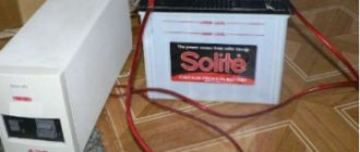
Now let's convert the computer power supply into a car charger.
Constant voltage charger
This device charges the battery with a constant fixed voltage of 14 V. As the battery charges, the charging current will drop. As soon as the voltage at the battery terminals reaches 14 V, the current will become zero and charging will stop.
Thanks to this algorithm, the battery cannot be recharged, even if it is left on charge for a week. This is useful when servicing AGM and GEL car batteries that do not like to be recharged.
And now let’s get down to business, especially since the modification scheme is simple. We will modify the ATX power supply on the TL494 controller or its analogues (see the section above). Our task is to increase the output voltage on the +12 V bus to 14 volts. This is not difficult to do. We open the power supply, take out the board and unsolder all the power wires, leaving only yellow, black and green.
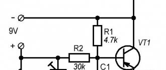
We solder the green wire in place of any black one - we issue a command to the power supply unit to unconditionally turn on when connected to the network (see the section above). We unsolder electrolytic smoothing capacitors from all power lines. In the place where the capacitor stood on the +12 V bus, we install a capacitor of the same capacity, but with an operating voltage of 35 V. We proceed to finalizing the controller. We find a resistor that connects the first pin of the microcircuit to the +12 V bus. In the diagram below it is indicated by an arrow.
We need to change its denomination. But which one? We solder it and measure its resistance. In our case, its nominal value is 27 kOhm, but depending on the power supply model, the value may vary. In place of the soldered one, install a variable resistor with a nominal value approximately twice as large. We set the resistor slider to the middle position.
We turn on the power supply and, measuring the voltage on the +12 V bus (yellow wire relative to black), rotate the slider. The voltage is easily reduced, but it cannot be increased - the overvoltage protection interferes. In order to raise the voltage to the 14 V we need, it needs to be turned off. We find a resistor and a diode in the diagram, indicated by arrows in the figure below, and unsolder them.
We turn on the power supply again, set the voltage between the black and yellow wires to 14 V. Turn it off, unsolder the resistor without touching its slider, and measure the resistance. In place of the variable we install a constant of the same denomination. We install two terminals on the case, solder the black and yellow wires to them, mark where the plus and minus are (yellow is plus, black is minus).
We turn on the power supply again, now a device converted into a battery charger. We connect the load to the terminals - the high beam lamp of the car. We measure the voltage at the terminals: if it has not decreased by more than 0.2 V, then the modification is complete. We assemble the device and use it.
Important! The final charging voltage for AGM and GEL batteries is 13.8 V, so it makes sense to reduce the output voltage from 14 V to 13.8 V.
Perhaps the only drawback of this homemade design is that it does not have protection against short circuits and reverse polarity (we turned it off). Therefore, you need to use the device carefully.
Advanced ways to change the voltage along the 12V line
The above method of raising the voltage along the 12V line by loading the 5V line is simple, but not the most correct way. There is certainly advantage. Ease of assembly, repeatability, availability of the element base - these are the main advantages of the above design. However, the surest way is not to load the 5V channel, but to simply adjust the variable resistor inside the power supply. As a rule, the voltage value on the 12V channel is determined using a resistive divider. By changing the position of the trimmer resistor, we get an increase or decrease in voltage along the 12V line. The exact location, rating, and method of adjustment depend on the specific model of the power supply. This method, although the most correct, requires you to know the circuit, as well as an understanding of the operation of the power supply. Some power supplies do not have such interlinear elements in principle; they have to change one of the constant resistors in order to somehow affect the operation of the PWM microcircuit.