In everyday life, a powerful power source with a fixed voltage is often needed. It can be used as a charger, to power audio equipment (amplifiers), etc. It is advisable to make such power supplies using a pulse circuit. This circuitry allows you to create lightweight and powerful DC voltage sources. The complexity of the circuit begins to fade into the background compared to its advantages already at load currents of more than 2A. You can make a switching power supply with your own hands if you have the equipment and certain qualifications.
Types and principle of operation of switching power supplies
The basic operating principle of a switching power supply (SMPS) is that direct voltage (rectified mains voltage or from a third-party source) is converted into pulsed voltage with a frequency of up to hundreds of kilohertz. Due to this, the winding parts (transformers, chokes) are light and compact.
Fundamentally, IIPs are divided into two categories:
- with pulse transformer;
- with storage inductance (it can also have secondary windings)
The former are similar to conventional transformer mains power supplies; their output voltage is regulated by changing the average current through the transformer winding. The latter work on a different principle - they are regulated by changing the amount of accumulated energy.
Based on other characteristics, IIP can be divided into unstabilized and stabilized, unipolar and bipolar, etc. These features are not of such a fundamental nature.
Breakdowns
Like any radio component, line transformers also break. Since the prices for some models are quite high, it is necessary to make an accurate diagnosis of the breakdown so as not to throw money away. The main malfunctions of TDKS are:
- breakdown of the housing;
- winding breakage;
- interturn short circuits;
- screen potentiometer break.
With a breakdown of the housing insulation and a break, everything is more or less clear, but an interturn short circuit is quite difficult to identify. For example, TDKS beeps; this can be caused both by the load in the secondary circuits of the transformer and by an interturn short circuit. The best thing is to use a device to check TDKS, but if there is none, look for alternative options. You can read about how to check the TDKS of a TV in the article on the website “How to check a transformer.”
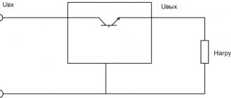
Structural and schematic diagram of the main parts of the block
Generalized block diagram of a pulse power supply.
A surge filter is installed at the input of the power supply. In principle, it does not affect the operation of a homemade or industrial switching power supply - everything will function without it. But you cannot abandon the filtering circuit - due to the extremely nonlinear shape of the consumed current, pulsed sources intensively “sprinkle” interference into a 220-volt household network. For this reason, devices running on the same network on microprocessors and microcontrollers - from electronic watches to computers - will malfunction.
Network filter circuit.
The purpose of the input device is to protect against two types of interference:
- common-mode (asymmetrical) – occurs between any wire and the ground (case) of the power supply unit;
- differential (symmetrical) – between the power wires (poles).
The filter, like the entire power supply, is protected at the input by fuse F (fuseable or self-recovering). After the fuse there is a varistor - a resistor whose resistance depends on the applied voltage. As long as the input voltage is normal, the resistance of the varistor is high and it has no effect on the operation of the circuit. If the voltage increases, the resistance of the varistor drops sharply, which causes an increase in current and the fuse burns.
Capacitors Cx block differential noise at the input and output of the filter in the range up to 30 MHz. At a frequency of 50 Hz their resistance is high, so they do not affect the mains voltage. Their capacitance can be selected from 10 to 330 nF. Resistor Rd is installed for safety - the capacitors are discharged through it after the power is turned off.
Common-mode interference is suppressed by a filter on Cy and L. Their values for the cutoff frequency f are related by the Thompson formula:
f=1/(2*π*√L*C) , where:
- f – cutoff frequency in kHz (the conversion frequency of the pulse generator is taken);
- L – inductance of the inductor, μH;
- C – capacitance Cy, µF.
The common mode choke is wound on a ferrite ring. The windings are identical, winding on opposite sides.
Common mode choke design.
Unlike the output filter, the rated current of the power supply unit does not affect the calculation of the noise protection filter elements, with the exception of the wire with which the inductor is wound.
After the filter, the mains voltage is rectified. In most cases, a standard full-wave bridge rectifier is used.
Recovery
A breakdown is usually a crack in the housing; in this case, repairing the TDKS will be quite simple. We clean the crack with coarse sandpaper, clean it, degrease it and fill it with epoxy resin. We make the layer thick enough, at least 2 mm, to prevent repeated breakdown.
Restoring the TDKS in the event of a break or short circuit of the turns is extremely problematic. Only rewinding the transformer can help. I have never performed such an operation, since it is very labor-intensive, but if desired, of course, everything is possible.
If the filament winding breaks, it is better not to restore it, but to form it from another place. To do this, we wind a couple of turns of insulated wire around the TDKS core. The direction of winding is not important, but if the filament does not light up, swap the wires. After winding, you need to set the filament voltage using a limiting resistor.
If the accelerating voltage (screen) is not regulated, then in this case it can be formed. To do this, you need to create a constant voltage of about 1kV with the possibility of adjusting it. This voltage is present at the collector of the horizontal transistor; the pulses on it can be up to 1.5 kV.
The circuit is simple, the voltage is rectified by a high-voltage diode and regulated by a potentiometer, which can be taken from the kinescope board of an old domestic TV 2 or 3USTST.
views
Inverter circuits
The resulting rectified voltage is supplied to the converter (inverter). It is performed on bipolar or field-effect transistors, as well as on IGBT elements that combine the properties of field-effect and bipolar ones. In recent years, high-power, low-cost insulated gate field-effect transistors (MOSFETs) have become widespread. It is convenient to build key inverter circuits on such elements. Switching power supply circuits use various options for connecting MOSFETs, but push-pull circuits are mainly used due to their simplicity and the ability to increase power without significant modifications.
Push-pull scheme
Push-pull converter circuit.
A push-pull inverter (push - push, pull - pull) is an example of a push-pull converter. Transistor switches operate on the primary winding of the transformer, consisting of two half-windings I and II. The transistors open alternately for a given period of time. When the top transistor in the circuit is open, current flows through half-winding I (red arrow), when the second one flows through half-winding II (green). To avoid a situation where both switches are open (due to the finite speed of the transistors), the control circuit creates a pause called Dead time.
Transistor control taking into account Dead time.
This circuit works well at low supply voltage (up to +12 volts). The downside is the presence of surges with an amplitude equal to twice the supply voltage. This entails the use of transistors designed for twice the voltage.
Bridge circuit
The push-pull bridge is free from the main drawback of the previous scheme.
Push-pull bridge inverter circuit.
Here, a pair of transistors T1 and T4 , then T2 and T3 (the key control signal is generated taking into account Dead time). In this case, the primary winding is connected to the power source first on one side, then on the other. The pulse amplitude is equal to the full supply voltage, and there are no voltage surges. The disadvantages include the use of four transistors instead of two. In addition to increasing the size of the power supply, this leads to doubled voltage losses.
Half bridge circuit
In practice, a half-bridge inverter circuit is often used - to a certain extent, a compromise between the previous two circuits.
Half-bridge circuit.
In this case, one side of the winding is switched by alternately opening transistors T1 and T2, and the other is connected to the midpoint of the capacitive divider C1, C2. Advantages of the scheme:
- unlike push-pull, there are no voltage surges;
- unlike bridge, only two transistors are used.
On the other side of the scale, the transformer winding is powered by only half the supply voltage.
Single-ended circuits
In the circuitry of converters, single-cycle circuits are also used - forward and flyback. Their fundamental difference from push-pull ones is that the transformer (more precisely, its primary winding) simultaneously serves as a storage inductance. In flyback circuits, energy is accumulated in the primary winding during the open state of the transistor, and is transferred to the load through the secondary winding during the closed state. In direct thrusters, energy accumulation and release to the consumer occur simultaneously.
Two phases of operation of a flyback single-cycle inverter.
Restoring the device
Independent replacement and repair of TDKS is quite possible. Having determined the malfunction, you can restore the system. When considering how to connect a line transformer to televisions, it is necessary to study the procedure for resuming its operation. In the event of a complete replacement of a transformer device, it will be necessary to select new equipment with an appropriate terminal system. Only in this case will the technique work correctly.
If the equipment does not work due to a breakdown, it means that a crack has appeared in the housing. You can find it upon inspection. The crack will need to be cleaned, degreased, and then filled with epoxy glue. In this case, the resin layer must be at least 2 mm. This will prevent breakdown in the future.
Repairing the TDKS when the circuit breaks is problematic. You will need to rewind the reel. This is a labor-intensive process that requires high concentration from the master throughout the entire procedure. Replacing the winding is possible, but this requires some experience.
If the filament winding is broken, the line is formed from another place. In this case, insulated wire is used. The cable is wound around the core. The voltage is set by using a resistor.
Power transformer
The power transformer operates at high frequencies (up to several tens of kilohertz), so it can be made on a core made of ferrite rather than transformer iron. Also, due to the increased frequency, its dimensions will be smaller than that of a network one, designed for conversion at a frequency of 50 Hz. The calculation of a pulse transformer is quite extensive. You can understand it for general development, but for practical purposes it is better to use some program, including online services.
Interface of the Lite-CalcIT program.
The Lite-CalcIT program is popular. She can calculate a transformer for an existing core, or she can select the optimal one based on the entered data.
High voltage pocket generator
Various high-voltage generators are very popular among radio amateurs.
Most often this is a blocking generator, a line transformer from an old TV and a voltage multiplier from the same place. However, all such designs are quite powerful, which sometimes brings more inconvenience than benefit. In the article I will describe the process of assembling a high-voltage pocket generator (up to 10 kV), powered by 1 AA battery. It can be useful, for example, for checking a car's spark plugs, the quality of insulation, or to simply play with sparks (which in this case will be completely safe, since the output power of the generator is milliWatts). So, let's begin. The figure below shows a diagram of the device. In fact, this is a diagram of a regular lighter for a gas stove.
- GB1 – AA, AAA (1.5v)
- TV1 – Further in the article
- VT1 – 2n4403
- R2 – 2.4 kOhm
- C1 – 0.01 µF
- R1 – 220 Ohm
- VT2 – 2n4401
- VD1 – FR107
- R3 – 500 kOhm (Variable)
- R4 – 1 mOhm
- R5 – 10 kOhm
- VS1 – mcr100-6
- C2 – 470-1000 nF
- TV2 – Further in the article
Details of the first converter
Details of the second converter (1.8 mOhm replaced by 1 mOhm + 500 kOhm variable)
The part numbers are not critical. For example, instead of the 2n4401 transistor, you can safely install KT315, and replacing 2n4403 will be KT361. It is better to take pulse capacitors as C2 (for example, CBB21).
Now you need to wind the transformers. TV1 is wound on a core from a phone charger or an LDS ballast choke. First we wind the secondary winding. To do this you will need a 0.06 mm wire. You need to make 500 turns. It is not necessary to wind turn to turn with interlayer insulation (although it is preferable), since the voltage here will not exceed 190 volts. Then we make 2-3 turns of tape and wind the primary winding IN THE SAME DIRECTION AS THE SECONDARY. It consists of 10 turns of wire 0.32-0.56 mm.
After this, you can assemble the first part of the circuit (up to the diode VD1) and connect an indicator neon light bulb (like those installed in switches) to the output of the converter and connect the power. If everything is assembled correctly, the “neon” will light up, and quite brightly. If this does not happen, then try swapping the leads of the secondary winding and check the correctness of the installation as a whole.
TV2 swings on a rod from the magnetic antenna of an old radio. As in the first transformer, we first wind the secondary winding with 0.06 wire, but now strictly turn to turn, making high-quality interlayer insulation (2-3 layers of tape). There are 1500 turns in total. Then we put 4-5 layers of tape and wind the primary winding - 10 turns of 0.56 mm wire (in the same direction!). Now we assemble the circuit to the end (remembering to turn off the neon!), place the TV2 high-voltage terminals at a distance of 3-4 mm from each other and start the circuit.
To achieve maximum output voltage, we change the resistance of resistor R3. As soon as the discharges become the brightest and longest, the circuit can be considered tuned.
If you assemble the circuit onto a printed circuit board and make a housing for it, you will get an excellent kitchen gas lighter. I did not make a board, since I plan to assemble an electronic Ruhmkorff coil based on this circuit.
Source
Snubber
To compensate for current and voltage surges that inevitably arise when switching the primary winding of a transformer, damper circuits are used, called snubbers in English technical literature. Such circuits can be installed along the power supply (parallel to the primary winding of the transformer) or separately on each switch. The design of snubbers can be different, but the most widespread are dampers in the form of a sequential RC chain (diagram b in the figure).
Various damper schemes.
There is no substantiated method for calculating a snubber. To do this, it is necessary to take into account all parasitic inductances (windings, tracks, capacitors) at many frequencies and for unknown wave impedances. Therefore, all existing calculations are empirical in nature.
The main (and only) active element of the damper is the capacitor. It “absorbs” impulse emissions. The resistor only worsens the damping properties, but limits the current through the capacitor, which can reach significant values, albeit for a short time. This scheme is more relevant in thyristor converters.
You can find out what a snubber or damper is by watching the video.
The RCD snubber circuits (c and d in the figure) contain diodes. They can be useful for limiting reverse polarity pulses in thyristor and bipolar transistor circuits. If the switches are assembled on field-effect or IGBT transistors, then there is no point in installing valves - they duplicate the diodes present inside these transistors.
The capacitance of the capacitor is selected in the range of 0.1–0.33 μF. In 90+ percent of cases this is enough. An increase or decrease in value is used for keys operating under non-standard conditions (increased conversion frequency, etc.)
Peculiarities
Transformers of the TDKS type are today included in the TV circuit to provide the anode (second) kinescope with electric current with the required parameters. Outgoing voltage is 25-30 kV. During operation of the equipment, an electrical flow is generated. This accelerating voltage is 300-800 V.
Depending on the category of TDKS transformers, pinout, a secondary voltage is generated, which is additional to ensure frame-type scanning. Equipment devices pick up a signal from a kinescope beam at an automatically adjusted horizontal scan frequency in TV transformers.
The connection diagram and pinout in the presented transformer characterize the device. The device has a primary winding. An electric current is supplied to it for further development. The primary circuit supplies power for the operation of video signal amplifiers. The winding transmits electricity to the secondary coil. From here the power is supplied to the corresponding circuits.
Video: Line transformer
The line transformer is responsible for powering the second anode, accelerating voltage, and focusing. These processes are carried out in TDKS. Adjustment occurs using potentiometers. Transformers of the presented category are provided with a certain pinout. The pin arrangement can be in the form of the letter O or U.
Rectifier
The voltage of the secondary winding must be rectified. For levels up to 12 volts, it is advisable to use a full-wave, midpoint circuit.
Diagram of a rectifier with a midpoint and the passage of current through it.
The advantage of this circuit is that the current flows in each direction through only one diode, and the voltage drop across the valves, in contrast to the classic bridge circuit, is half as much. This can significantly reduce the required number of turns of the secondary winding. The same purpose is served by the use of Schottky diodes and assemblies of them.
Bridge rectifier circuit and current flow through it.
If the output voltage of the power supply is higher than +12 volts, then saving 0.6 volts becomes insignificant, and you can make a rectifier according to the standard circuit and use a transformer without a tap.
If the output of a switching power supply must be bipolar, tapping from the midpoint again becomes rational. In this case, 4 diodes and radiators for them are saved at once - the gain in size can be significant.
Bipolar rectifier with midpoint.
Breaking
Line devices may fail. In this case, the operation of the TV and monitor will be impossible. There are many varieties of row aggregate models. Replacement is difficult. The cost of analog devices is high. Some TVs and monitors require large repair costs. The necessary parts are sometimes difficult to find.
In order to purchase only that part of the circuit that has failed and quickly replace it, you need to check the line transformer. It will be easier for the TV to undergo adequate repairs. First of all, check for the following faults:
- Circuit break.
- Breakdown of the sealed housing.
- Short circuit between turns.
- Potentiometer break.
The first two breakdowns are quite easy to identify. This is determined visually. To replace faulty elements, material can be purchased at almost any radio equipment store.
It is more difficult to determine a short circuit in the winding circuits. In this case, the transformer produces a sound resembling a squeak. But repairs are not always required when such a signal appears. TDKS sometimes beeps due to high voltage on the secondary circuit. Check what is causing the sound using a special device. If there is no equipment, you need to look for other options.
Checking with an oscilloscope
If the TV needs to be checked in the TDKS system, the check is performed using an oscilloscope.
To repair the TV, you will need to cut off the power supply to the device. Next you need to find the secondary circuit. Its operation is examined when connected to the cut-off power supply terminal of the TDKS through R-10 Ohm. Replacement or repair of the device will be required if the connection to the oscilloscope reveals abnormalities. The following deviations are possible:
- The interturn short circuit shows a “rectangle” with large noise at R=10 Ohm. Almost all the tension remains here. If there is no fault in this area, the deviation will be determined by fractions of a volt.
- If there is no secondary voltage, the circuit needs to be replaced. There was a break.
- When R=10 Ohm is removed and a load of 0.2-1 kOhm is created on the secondary circuit, the load at the output is estimated. It should repeat the incoming indicators. If there is a deviation, the TDKS must be repaired or completely replaced.
There are other breakdowns as well. You can identify them yourself.
Filter
The output voltage must be filtered - it contains a large number of conversion products. Since the inverter operates at a fairly high frequency, filters containing not only capacitors, but also small-sized chokes with relatively low inductance become effective.
L- and U-shaped LC filters.
To calculate the filter elements, it is necessary to specify the pulsation coefficient Kp. It is selected from the expected load:
- sensitive equipment for radio reception, preliminary stages of audio equipment, microphone amplifiers - Kp = 10-5..10-4 ;
- audio frequency amplifiers – Кп=10-4..10-3 ;
- middle and low class receiving and sound reproducing equipment – Kp=10-2..10-3 .
For an L-shaped filter installed after a full-wave rectifier, the following relations apply:
- L*C=25000/(f2+Kp);
- L/C=1000/R2н.
In these formulas:
- L – inductance of the inductor in µH;
- C is the capacitance of the capacitor in microfarads;
- f – conversion frequency in Hz;
- Rн – load resistance in Ohms.
For U-shaped filter:
- С1=С2=С;
- L/C=1176/R2н.
The dimension of the values is the same as for the previous filter.
Improving Models
There are many similar inventions, but their power is not high enough. To charge a phone, you need at least 2 W at the output of such a motor for an old model of a mobile device and at least 5 W for a modern smartphone.
Where can I get a high-voltage module with good power? Let's try to do it ourselves. We will select a convenient rotation handle for the stepper, and connect all the wire leads according to the diagram. The resulting DC outputs will go to the wattmeter and to the load, which is selected for this engine and the speed according to the optimal parameters.
What kind of power can be developed on a large stepper motor at a speed of 120 per minute? Let's start the experiment. The wattmeter shows 0.8 W at a voltage of 6 volts and a current of 0.11–0.12 amperes. At faster rotations, the peak figure reaches 1 ampere, but this is at very fast speeds.
Therefore, such a device requires improvement. You need a converter that increases the speed by 3-4 times so that you can successfully charge your phone while traveling.
For this, a commutator motor is used. You can make a belt drive for this engine to increase its speed by 3 times. The result is an installation with a pulley diameter that is 3 times larger than that installed on the stepper motor. Now such a device will rotate 3 times faster, which will allow it to reach 2–2.2 W. In this case, the voltage is 17 volts, the current is 0.12-0.13 amperes. This power is already more significant. If the device is mounted on a table, turning the handle is quite simple.
The higher the rpm, the more useful power the generator can produce.
Circuits and manufacturing of switching power supplies
Switching power supplies are assembled on various element bases. Typically, specialized microcircuits specially designed for creating such devices are used to build SMPS. Except for the simplest blocks.
Powerful pulse unit on ir2153
Simple power supplies can be built on the IR2153 chip. It is a powerful integrated driver with a timer similar to the NE555. The generation frequency is set by external elements. The microcircuit does not have inputs for organizing feedback, so current and voltage stabilization cannot be obtained using the PWM method.
Pin layout of the IR2153 chip.
The assignment of the pins is given in the table.
| № | Designation | Purpose | Purpose | Designation | № |
| 1 | Vcc | Power supply for logic and drivers | Power output switches | Vb | 8 |
| 2 | Rt | Frequency setting resistor | Top Driver Output | HO | 7 |
| 3 | Ct | Frequency setting capacitor | Top Driver Power Return | Vs | 6 |
| 4 | COM | General | Bottom Driver Output | L.O. | 5 |
Internal circuit of IR2153.
To better understand the operation and pin assignments, it is best to study the internal circuitry. The main point that you need to pay attention to is that the output switches are assembled using a half-bridge circuit.
Using this chip you can assemble a simple power supply.
Scheme of a simple power supply based on IR2153.
The IR2153 is powered by 220 volts through a quenching resistor R1, a diode rectifier VD3, and a filter on C4. The generation frequency is set by elements C5, R2 (with the values indicated in the diagram, it turns out to be about 47 kHz). A transformer can be considered a program. The author's version used a power transformer from a computer power supply. The standard windings have been removed, the primary is wound into two cores with enamel insulated wire with a diameter of 0.6 mm.
Universal converter type
In order to make a step-up voltage converter with your own hands combined with a step-down voltage converter with your own hands, you will need to make some improvements and elements such as:
- high-voltage converter device up to 400 kiloVolt;
- module for enhancement;
- low-voltage conversion device 5Volt to 1.5Amp;
- 500W boost converter;
- voltage regulation kit.
The compact device produces high power with a single-cycle operating mode. Typically, such standard devices are capable of performing only one function. Increase or raise the voltage. A universal proprietary solution can combine these two features.
To test self-made devices, a variety of power supplies are used. The devices can be charged and used for various tasks.