One day on Instructables I saw a project that formed the basis of my idea, the implementation of which I want to talk about today. The author of this project, a user with the nickname Ananords, created an RFID-controlled player designed for children and people who, for some reason, cannot use regular MP3 players. That project was called Juuke. Ananords created it for his beloved grandmother. This is a device that is perfect for people with Alzheimer's syndrome or dementia. This feature of the project caught my attention, since something similar happened to my grandmother, an illness took her from us, and I knew that she would like the player that will be discussed.
It works like this: there is a player with two buttons. One allows you to play music or pause playback, and the second allows you to shuffle songs. In addition, you can select an RFID card and present it to the reader, which allows you to turn on a specific song. This, in essence, reproduces the process of listening to music in ancient times, when to turn on the desired recording you had to insert an ordinary CD or an ordinary cassette into the player. But here the old approach is complemented by new technologies, which makes it easier for people with certain disabilities to listen to music. Even though my grandmother is no longer with us, I still wanted to do this project. When my parents were cleaning out the house, I came across my mother's old cassette recorder. “Eureka!” I thought. As a result, this tape recorder formed the basis of my version of Juuke. I basically did everything the same way as Ananords and everything worked as expected, but I also expanded the project with some of my own ideas. Namely, we are talking about the following:
- Ability to play an entire album using one RFID card.
- Possibility to skip a recording and go to the next recording.
- The ability to play music “recorded” on different “sides” of the card (A and B), which is reminiscent of playing regular cassettes.
- Using the same number of buttons, but using short and long presses on them.
Now let's get down to business.
Materials and tools
When selecting materials for my project, I deviated a little from the set of components that was used in Juuke. This is what my player is made of:
- Arduino Nano board (instead of the Arduino Uno board used in Juuke).
- DFPlayer Mini audio file player module.
- MicroSD card.
- RFID module RC522. (They say that you should buy a couple of these at once, since some of them arrive already in non-working condition. But I only ordered one. It turned out to be in perfect order. Maybe I was just lucky.)
- RFID cards (I ordered 100 pieces).
- Momentary push buttons, 2 pieces.
- Wires.
- 1 kOhm resistor.
- Covers for connectors.
- An old cassette recorder (that still works).
- Colored LEDs.
- External battery with USB support.
- Prototyping board.
Here is a list of optional materials:
- A 10 kOhm variable resistor (I did not use this one, since the tape recorder has a knob for adjusting the volume).
- Stereo jack (AUX) (I used tape recorder speakers).
- Bread board.
- Connecting wires.
- 5V power supply.
- Power connector.
Tools:
- Soldering equipment.
- Wire stripping tool.
- Computer and color printer.
We'll also need a Canva account.
Schematic diagram
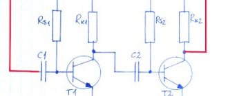
The tape recorder circuit is shown in Fig. 1. The preamplifier is built on transistors VT1 and VT2 [1].
Transistors have a significant gain and low noise level (the latter indicator is very important). The bias of the transistors is set by resistors R1 and R4.
Capacitor C1, together with the playback head BS1, forms an oscillating circuit tuned to a frequency of 12500 Hz (for film with a working layer Fezft) or at a frequency of 14000 Hz (for film with a working layer C). This capacitor is selected for a specific head.
Isolation filters C3R3 and C5R6 prevent self-excitation of the amplifier. Chain C7C8R8 reduces the background level from a running engine. The power amplifier is made using transistors VT3, VT4, VT5 and VT6 in a push-pull circuit.
The amplifier has an output power of 0.5 W. The engine speed stabilizer (ERS) in imported microelectric motors is most often installed directly in the motor housing. If you use a domestic electric motor, then you can take a ready-made SOD on the KR198NT1B microcircuit.
Rice. 1. Schematic diagram of a homemade tape recorder.
The power supply for the tape recorder is normal, without stabilization. It is soldered onto transformer T1 and diode bridge VD1-VD4. Capacitor C11 smoothes out alternating current ripples. The power switch S1 is combined with the volume control R7. The switch is included in the DC circuit so that there is no background interference at the amplifier input.
Contacts S2 are placed directly on the tape drive mechanism (TFM). They are closed during rewind and playback mode. The VD6 LED is very interesting. If the contacts S2 are open, that is, the engine is turned off, it shines dimly, and if they are connected (the engine is running), it lights up brightly.
ULF on K174UN14 or TDA2003
The tape recorder amplifier has a low output power. It can be increased by using a second amplifier with higher output power. For example, such an amplifier can be made on the fairly common TDA2003 microcircuit (the domestic analogue is K174UN14).
Rice. 3. ULF circuit on the K174UN14 or TDA2003 chip.
Its diagram is shown in Fig. 3. The amplifier has good characteristics and produces an output power of 4-6 W. The scheme has no special features. When self-excitation of the microcircuit, a chain Cdop Idop is added (Cdop = 39 pf, Idop = 43 Ohm).
When using this amplifier, diodes VD1-VD4 are replaced with more powerful KD202, and transformer T1 is used with a power of at least 15 W (for example, TVK-110).
Homemade cassette recorder
I admit right away that there was no practical need for the manufacture of this device. It’s just that, one fine day, I came across an indication unit (2.7.46.009), which was gathering dust in my collection of electronic spare parts, a use that I had been wanting to find for a long time (I really liked how such indicators used to work in Soviet tape recorders) and an empty case from a faulty computer power supply, black.
The thought of assembling a simple tape recorder, not even a tape recorder, but a cassette player, has occurred to me more than once - I have accumulated at least a hundred cassettes in my home collection during the peak of their popularity as a carrier of audio recordings, and now I can’t bring myself to throw them in the trash. Although all the recordings that are present on them are not difficult to find on the Internet in more decent quality. But that's how it happened. Initially, it was planned that the tape recorder (that’s what I will continue to call my design) would be a simple device, without a power amplifier, that could be connected to the linear input of the sound card of any computer (laptop) and listen to recordings using its amplifier and speakers. The tape drive mechanism (TFM) from a faulty Chinese double-cassette player has been on the radar for a long time. In general, I did not experience a shortage of various spare parts during the assembly process, since during my passion for electronics, I (like probably any radio amateur) had accumulated a fair amount of all kinds of electronic devices that could not be repaired.
A lyrical digression - the reader of this text may immediately have a question - “what the hell, sorry, there’s an indicator, a housing from a power supply and, in general, it wouldn’t be easier to find (buy, repair) a ready-made player (tape recorder) and adapt it to your goals. What is this whole structure for? I answer - solely for my own pleasure! As they say, I remembered my childhood, inspiration struck))). I can’t count how many different designs I’ve remade! But, gradually, there was less and less time for hobby, and the need to make something with your own hands practically disappeared - stores were filled with all kinds of electronic devices, and it really became easier to buy them than to do it yourself. But here it is, “it’s over,” as they say, so all questions like “what the hell” have one answer in this case – “for my own pleasure.” Therefore, one should not look for special logic in the entire structure.
That's it, enough "water" - I'll move on to describing the assembly process.
The main conditions for the manufacture of a tape recorder were the lowest possible financial costs and the use in the design of as many ready-made components and parts as possible. The prospect of inventing, drilling and etching printed circuit boards no longer inspired me. Although, undoubtedly, the design would have been more attractive.
I started by looking for a power supply unit (PSU). Since the indicator required a bipolar voltage of 15 V and an alternating voltage of 5 V, switching power supplies (UPS) from Chinese DVD players (of which I have accumulated 6 of them - with dead lasers and beyond repair) almost ideally met these parameters. I chose the one that suited the dimensions better.
The LPM motor (with a built-in rotation stabilizer) was powered by 9V, so the +15V arm of the UPS was suitable for it (we had to additionally solder a 9V stabilizer).
I used the playback amplifier from the Zvezda 204 RM SA car radio, which I once regulated at the factory in my native Sergiev Posad, where the radio was produced. Power supply for the shock wave also required +9V.
During the assembly process, I decided that in addition to the line output, the tape recorder should still have a headphone amplifier, so that even if there was no computer, it could be used.
As a telephone amplifier, I used an amplifier from an old CD-ROM that had expired. Fortunately, they were produced for a long time with a volume control. All that remained was to cut it out from the common CD-ROM board and find out how to connect the power (+5V) and the input signal, which was not difficult.
A second similar amplifier was subsequently used as a linear amplifier for a radio receiver.
After the whole structure was successfully working “on the knee”, I didn’t want to give up the idea at all, I decided that the tape recorder would definitely be assembled. And the process itself brought a lot of pleasure!
The next stage of assembly was the placement of the components in the empty case of the computer power supply, which was supposed to serve as the case of the future tape recorder.
But a difficulty arose - the very close location of the switching power supply and the tape head of the CVL (it was planned that the CVL would be placed horizontally and mounted on the top cover) created strong interference in the form of an unpleasant high-frequency squeak. The indicator also added its contribution to the general source of interference. It became clear that it would not be possible to place the structure in the case of a computer power supply and still obtain an acceptable level of interference - there is too little space, and shielding the UPS does not help.
Therefore, I decided not to limit myself to the size of just one power supply unit, but to use it as the base of the case. I placed the LPM vertically, placed the UPS on the opposite wall of the case, as far as possible from the magnetic head, and since there is now much more space, I added a power amplifier (PA) so that it would be possible to connect loudspeakers. But to power the PA, a separate power supply was required. The power of the UPS was barely enough to power the remaining units.
An external UPS from the printer was found that produces +24V output at a current of 1A.
Which, alas, burned out during the process of adjusting the design (the tester’s probe jumped off and unsuccessfully closed some circuit in its circuit - it was clearly not my day))) and it was no longer possible to restore the circuit. I had to place a transformer and a diode rectifier on its board, removing parts. By the way, in my designs, as circuit boards, I often use boards from unnecessary devices (of course, having first removed standard radio components from them, connecting existing tracks with jumpers where necessary, or cutting them with a scalpel). The designs on such boards look very good. Therefore, in the photo at different times there is a pulse unit and later one made using a transformer.
But, since the MIND has already appeared, there must also be a volume control, and therefore tone controls - “Ostap got carried away...”)))).
The PA was assembled on a TDA2005 chip according to a standard circuit, and the tone and volume control was on an A1524 (the domestic analogue is K174XA48). As boards I used universal circuit boards purchased at a radio parts store.
The design of the tape recorder became more and more complicated, and the assembly process became more and more delayed. As a result, it was decided to add a radio receiver to the circuit, thus turning the tape recorder into a radio tape recorder. A suitable radio module board was found in yet another time-worn Chinese tape recorder. The tuner, made on a single KA2292 chip, included FM, MF, DV, HF stages, a stereo decoder and indicators for fine tuning and the presence of a stereo signal. To power it, another “+4V” voltage stabilizer was manufactured.
After debugging the electronics, the question arose of the final design of the entire structure. A second power supply from a computer with a cut off side wall was used as the top cover of the case.
The connection of both housings is made using a metal plate and two vertical posts. After preliminary assembly of the case components, it turned out that there was enough space in it to accommodate two more speakers)))).
The side walls with holes for them were 4 mm plywood plates. The top cover was also made from plywood.
I covered the plywood parts with self-adhesive black film, and painted the power supply housings with black acrylic enamel - a spray sold in spray cans at paint stores. Later I covered the film on plywood with the same enamel.
After the tape recorder was assembled and work on it was almost completed, an FM transmitter was picked up on the street, apparently lost by some absent-minded car enthusiast. I couldn't resist adding the ability to play MP3 files to my design.
Work has resumed. In the front panel, I strengthened the USB connector for connecting flash drives, and placed the transmitter board under the top cover of the tape recorder, having previously cut holes in it for the indicator and control buttons. I connected the transmitter to the +15V circuit of the UPS.
At this point, work with the electronic part was completed. All that was required was the external design of the tape recorder. You can see the results of the work in the photographs.
The total financial costs ultimately did not exceed 500 rubles.
The pleasure received from creativity cannot be counted at all))).
ps…..if someone managed to read this text to the end, please accept my sincere gratitude!
Everything described above was posted here for the sole purpose of sharing the results of my work, perhaps someone will be interested. (And the case from the computer power supply is black, still awaiting use)))!
4.2 / 5 ( 43 voices)
Details
Transistors VT1 and VT2 can be taken type KT3102E (V, G, D) with a gain of at least 400; transistors VT3 and VT4 type KT315, KT3102 with any index.
The following pairs can be used in the output stage: MP38 and MP39, KT503 and KT502, GT404 and GT402, KT815 and KT814. They do not require radiators.
The SOD is ready-made at the factory; if it is not available, you can solder a homemade one according to the diagram in Fig. 2 [1, 2]. Transistor VT2 of any type KT with the appropriate structure and with a gain of at least 200. VT1 type KT816, KT814.
Rice. 2. Engine speed stabilizer circuit.
Resistor R3 regulates the engine speed. Debugging the tape recorder is almost not required.
You just need to set the film speed (4.76 cm/s) and adjust the head. It is also necessary to select capacitor C1 (Fig. 1) for a specific head. How to do this is described in detail in [1].
In case of unstable operation, it is necessary to select the resistances of resistors R1, R4, R11 and R13. The voltage at the connection point of the emitters of transistors VT5, VT6 should be equal to half the supply voltage (it is selected by resistor R11).