The accuracy of processing parts on metal-cutting equipment is monitored using optoelectronic sensors of an optical ruler installed on the machine bed. The analog signal from the sensor is sent to a digital display device (DRO), converted to digital and visualized in the form of numerical values for the movement of a tool or part along the feed axes.
The design of the optical ruler is quite simple, but reliable, providing high accuracy (up to fractions of microns) of measurements. Its main elements are: a transparent ruler with microscopic shading applied and an optical reading head moving along the ruler. As the reader moves, it reacts to a series of marks and gaps; the analog signal is transmitted via cable to the digital display device. The DRO converts the number of passed lines into digital information and displays it on its display. The ruler has from one to several reference points for setting the origin of the movement (zero coordinates).
Optical meters (rulers) are widely used both in new equipment and when re-equipping and modernizing old machine tools. The economic effect of using linear optical sensors is directly related to increased metalworking productivity and simplified operator work.
All digital display devices (DROs) on sale from can be viewed at the link - /katalog-stankov/tokarnye/misc/.
Electronic ruler - homemade
Sometimes determining the distance between two objects is a long and troublesome task due to their distance from each other.
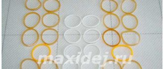
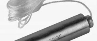
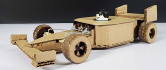
You can make this work stress-free and quick by using an electronic ruler, which you can make with your own hands in the evening using a calculator and a couple of spare parts. By the way, the principle that underlies this idea may be useful for developing other crafts. To create a homemade electronic ruler we need: – a toy machine; – reed sensor with magnet; - calculator.
Let us first explain how the author of this useful homemade product came to his plan. From geometry we know that the circumference of a wheel has a certain length. Knowing it and the number of revolutions of the wheel, it is not difficult to determine the distance that the wheel and, along with it, the machine, will cover from one object to the second.
To quickly calculate the number of revolutions of the car wheel and, accordingly, the distance from A to B, we use a calculator, or rather, its addition function. To close the contacts that will count the summation units, we will use a reed switch.
Discussion
The machine is, of course, nonsense, but the essence is clear; besides, with this device you can subtract distances and measure the area, but a scooter or bicycle for measuring long distances is already a thing! Question to enemies with comments like “smart people use roulette”, etc., etc., have you ever come up with something, invented something? No? Well, use the roulette that was invented long ago before you and don’t stink - it’s not your prerogative to think - that’s the job of the inventors.
You can use thread, for example. Fortunately, a skein of thread is not expensive. We measure the length of the thread and fold the thread in two, again in two, again and so on until the length becomes suitable for measurement with a tape measure or ruler. Then we simply multiply the length by two the number of times we folded the thread.
This method is convenient for measuring curved distances. It would be more correct to even call the video ELECTRONIC CURVIMETER with your own hands. It is convenient to measure the path you travel on foot, or for example, a curvimeter is widely used in road work, to measure distances along the road to control markings, dividing into sections (pickets), etc. And by design, for example, you can increase accuracy by placing several magnets at equal intervals in the wheel and summing up not the circumference and the length of the arcs between the magnets.
Listen, your blue screwdriver comes with 16 different bits, right? It looks like I have the same one, how did you deal with the fact that there is no magnetic holder? I inserted a small neodymium magnet from old headphones inside))) It would be cool if you made lessons with a few of these little modifications)
kakpravilno @Dan Brown yes, 16 nozzles. There is a magnet there, maybe someone took it out of you or didn’t put it in at all. This is a Chinese screwdriver).
Alexander Markov A year ago Author, does the frequency at which the wheel rotates greatly affect the accuracy of the calculations? For example, does it make sense to attach such a structure to a bicycle in order to measure the kilometers traveled if you ride quite fast?
Alexander [DF]Dips[C4Tm] And the position of the magnet at the beginning and at the end? no matter what you make the wheel from, it won’t be accurate, and the larger the wheel, the more jambs)) the hat is full.
Eargon @Alexander Nezvets you can put more magnets. There are 10 magnets on one wheel - then the error is smaller... Think with your head...
Making an inductive sensor
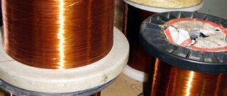
A cross-shaped reamer of the box is cut out of the press, four holes are pierced in its bottom, into which flexible stranded wires for the coil terminals are threaded, the ends of the coils are soldered to them, the reamer is bent to form a box, wrapped with adhesive tape or electrical tape, another plastic pin is threaded through (plastic after the hole for fastening is removed and a hole for fastening is obtained), the pin with the coils is also centered and fastened and, finally, filled with epoxy. The coils are soldered into place with flexible leads, each in its place, phased to obtain generation, the sensor is attached to its place, next to it is the generator board.
Nowadays, such coils or similar ones can be found in many no longer needed, broken or outdated devices, for example in floppy drives. There are ready-made coils and sensors, but they can’t always be purchased, and it’s not always cheap. Well, doing it yourself is also a pleasure for someone, especially if it works no worse, and in some cases better than finished products.
Source
Optical ruler: principle of operation, types, how to choose
The accuracy of processing parts on metal-cutting equipment is monitored using optoelectronic sensors of an optical ruler installed on the machine bed. The analog signal from the sensor is sent to a digital display device (DRO), converted to digital and visualized in the form of numerical values for the movement of a tool or part along the feed axes.
The design of the optical ruler is quite simple, but reliable, providing high accuracy (up to fractions of microns) of measurements. Its main elements are: a transparent ruler with microscopic shading applied and an optical reading head moving along the ruler. As the reader moves, it reacts to a series of marks and gaps; the analog signal is transmitted via cable to the digital display device. The DRO converts the number of passed lines into digital information and displays it on its display. The ruler has from one to several reference points for setting the origin of the movement (zero coordinates).
Optical meters (rulers) are widely used both in new equipment and when re-equipping and modernizing old machine tools. The economic effect of using linear optical sensors is directly related to increased metalworking productivity and simplified operator work.
All digital display devices (DROs) on sale from can be viewed at the link - /katalog-stankov/tokarnye/misc/.
Recommendations for choosing a DRO
When choosing a device, you must consider the following:
- screen - it is better to take one with an LCD display, all parameters will be accurately displayed, in some models the calculations are corrected;
- price - the DRO device is not cheap (from 10,000 to 50,000 rubles), if it is not absolutely necessary, then you can purchase a magnetic or optical ruler;
- number of axles for equipment;
- determination of measured values.
DRO and optical rulers on a lathe allow you to control the execution of the machine. Equipping a lathe or router with new measuring instruments will allow the operator to work with much higher accuracy and a reduced likelihood of making mistakes.
Basic parameters of the optical line
- Working length.
- Accuracy.
- Signal type.
- Measurement discreteness.
| Optical ruler KA600 |
Working length
The length of the optical ruler must be greater than the nominal stroke of the machine. It is not the magnitude of the stroke that should be taken into account, but the distance between the rigid stops along the measured axis. This will prevent failure of the reading sensor (head) due to the fault of the operator or in case of malfunction of the equipment limit switches. The recommended working length of the electronic digital ruler is based on the maximum amount of movement along the axis +100 mm
The longer the measured length, the larger the cross-section and size of the reading head. It is necessary to ensure minimal deformation of the measuring glass installed inside the housing. The opposite statement is also true - the smaller the measured axis stroke, the smaller the optical ruler and reading head can be
Accuracy
You should not purchase a ruler based on its high accuracy class (fractions of microns). The higher the measurement resolution, the higher the price of the meter. An optical ruler will not increase the accuracy of the machine; this technical characteristic depends on the rated accuracy and the actual state of the mechanics and backlash of the supporting surfaces. External factors are also important: the level of vibration during equipment operation, temperature, etc. Without eliminating all negative conditions, without modernization and compliance with the rules of normal operation of machines, it is impossible to achieve even the passport parameters. And a precision measuring system in the form of a high-precision optical ruler will not help in this case.
Signal type
The increased speed of the transmitted signal is provided by TTL logic (signal type - rectangular pulses of phases A, B, Z with an amplitude of 5V). Pulse resolution of several microns (from 0.5 to 5) minimizes measurement error.
It is possible to use a reading head with an RS-422 signal (phases /A, /B, /Z are also present).
Measurement resolution
The sensitivity value of the optical ruler. For example, the designation of a resolution of 5 µm means that the electronic ruler will transmit a signal to the DRO or CNC (1 pulse of phases A or B) when moving equal to or greater than 5 µm. Inside this zone it is difficult to track the position of the axis. Reducing the measurement discreteness (increasing accuracy or narrowing the dead zone) requires increasing the accuracy of glass manufacturing and marking, which leads to an increase in cost. A large number of pulses can ultimately also become a limiter for the maximum speed of movement along the axis, i.e. the device receiving the signals may not perceive all the pulses, and the position will be lost
If we compare optical and magnetic meters (both of them are used quite actively today), then the latter do not have a standardization of the accuracy class of the readings; as a rule, the measuring error of magnetic rulers lies in the range from ±20 to ±40 microns per meter.
Design and Application
An oscilloscope is a complex electrical device. A block diagram will help you understand the principle of its operation.
There are two scanning beams : vertically - Y and horizontally - X. Time values are plotted along the X axis, and the signal amplitude is displayed along the Y axis.
Y receives a signal from the device . It then passes through an attenuator, which changes the sensitivity of the circuit. Then, after passing through the pre-amplifier, it enters the delay line , which “holds” the signal until the sweep generator operates. The final amplifier outputs the signal to the oscilloscope screen. The higher the input voltage, the greater the amplitude of the signal.
A sawtooth voltage is applied to X from the sweep generator, due to which the signal on the oscilloscope is “stretched” in time. By changing the generator dimension, you can obtain an image with a scan time of up to thousandths of a second.
To ensure that the sweep starts simultaneously with the arrival of the signal, the device has a synchronization system . There are 3 possible clock sources:
- Measured signal . The most commonly used option, especially when the incoming source frequency is constant.
- Electrical network . The network frequency is maintained with high accuracy, so synchronization is possible through it.
- External source . It is used both as a laboratory signal generator and as a smartphone with an application that generates clock pulses of a certain frequency.
The oscilloscope visualizes the waveform , which helps to understand the cause of the malfunction. Using the device, the frequency response of the device is measured, it is possible to find out the rate of rise of the pulse in digital devices.
Oscilloscopes are used to configure and repair electronic devices, be it household appliances, vehicle repairs, or orbital stations.
What to choose: magnetic or optical ruler
With the required high accuracy (up to 2-3 microns for every meter of movement), optoelectronic meters (rulers) are used on metal-cutting equipment of almost any type. Focusing on financial benefits, equipment is often equipped with magnetic rulers that have lower measurement accuracy. But the price of a magnetic meter begins to outperform the cost of an optical ruler only for models with a working length of half a meter or more.
Magnetic rulers:
- Used primarily on grinding and boring machines; it is economically feasible to use when measuring lengths from 3 m
- Not used on machines with an error of less than 10 µm/m. In this case, turning, milling, grinding and other types of metal-cutting equipment are equipped with optical sensors.
| Magnetic ruler KA800M |
KA-800 is a series of rulers with magnetic tape. It is used on machines with moving units of more than 3 meters. The SDS6 display system can simultaneously work with both optical and magnetic rulers
Optical rulers
The KA series of optical lines from Guangzhou Lokshun CNC Equipment ltd takes into account almost all requests from both manufacturers of metal-cutting equipment and end consumers. The series is characterized by high measurement resolution (a signal is transmitted every 1 or 5 µm of movement depending on the resolution of the ruler), which minimizes positional error. Optical rulers are equipped with housings that protect working surfaces from metal shavings, sludge, and coolant.
- KA-200 - linear displacement sensors, have a small overall cross-section (16x16 mm), are installed in narrow places, and are used for specific measurements.
- KA-300 is an optical ruler with a working length of 70-1020 mm, characterized by a simple and rational design and sufficient rigidity. The most popular product.
- KA-500 is a special ruler with an optical head for movements from 70 to 470 mm. It is compact and can be installed in confined spaces.
- KA-600 - despite the considerable length of the meter, it is characterized by sufficient rigidity, achieved by installing additional supports and clamps in any accessible places along the length of the ruler. Thanks to this, with a working length of 1000 to 3000 mm, it has significant vibration resistance.
To take into account all the parameters and characteristics when choosing an optical line, consult a specialist.
Review of popular models
The most popular models among lathe operators are the following:
| Optical rulers | • KA (800, 600, 500, 400, 200). • DRO. • Ditron. |
| DRO | • JMD is a DRO system for the JET JMD-3T machine, but is suitable for many options. • DRO (DRO) - universal option. • Ditron is a universal option. • JET - designed for installation on vertical milling and drilling machines. |
Vampire-M6 › Blog › DRO on the Corvette 414 and why optical rulers are simply necessary
We are gradually moving towards CNC control on a milling machine and are trying to solve in advance all possible problems that may later arise on the way to CNC control.
The first thing that scares you is the need to turn the handles while the motors are connected. They say that intense torsion can cause electronics to burn out. And if I want to install a ball screw, then the readings of the dials will go far and for a long time, because the thread pitch will change. And if the motors are running, the spindles will begin to rotate and there may be an imbalance.
The most logical thing would be to switch to completely electronic control, but this would require movement control, because there would be no dials. And here, the most logical solution is not to get attached to the screw or dials, but to install optical rulers and a digital display unit (DRO). This will allow you to control movements directly on the “calculator” screen, ignore backlash and, if necessary, make simple calculations.
We go to Ali, find the cheapest one, similar in appearance to the more expensive one, see that there are positive reviews in Russian and order with delivery from the Russian Federation (secretly hoping that the package will not go like my new chair, which traveled from Ussuriysk for almost a month and a half). A special coupon from Ali also helped here, which saved me 500 rubles.
After payment, I corresponded with the seller for another day to clarify the length and accuracy of the rulers. There was a little trick there. The total length of the ruler is usually 142mm longer than the working stroke. I took the lengths almost at random, estimating the moves and measuring the installation dimensions on the machine, and as it turned out, all the calculations were close to reality. Those. 150 - 400 - 500 - these were the moves, and the lengths of the rulers were 292 mm, 542 mm and 642 mm. Of course, instead of 292mm, it is better to take the next size, i.e. 350mm, but more on that later.
As for accuracy, I didn’t really choose what was offered in the kit, so I bought it. Those. 5u = 0.005mm. As it turned out, the accuracy is more than enough and it simply blows your mind when you see three digits after the decimal point. The indicator itself can also show 1u - 0.001mm with rulers, and this is probably even more fun, trying to hit such precision on a Chinese milling machine, with its backlash dials. (When I manage to knock out all 000, I consider myself very cool). The dials on my Corvette, by the way, are only 0.01 vertically and 0.02 horizontally. (The latter are generally very interesting, they show 2 times more than needed, and I realized this only after installing the rulers. Fortunately, I didn’t manage to screw up anything on this machine).
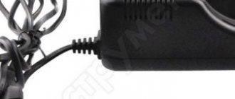
The parcel arrived quite quickly, like just two weeks from the date of purchase. I unpacked it, there were rulers with five-meter hoses (they probably thought that the machine was in my basement, and I would control it from the attic), the DRO display unit turned on only after a strong blow from the side, like an old TV.
(Inside there was a wire dangling around the power connector, which I crimped and put in place). In the box with the DRO there was a bag of bolts and instructions in English, which did not describe how to attach all this junk. But they put several brackets with holes, like a construction set, “assemble it yourself as best you can from what you have.”
I had to go online and look for photos of the DRO installation on Russian forums and DRO on English-language forums. I haven't seen enough. People have golden hands, although they grow from the wrong place. But it’s okay, I more or less understood that you can fix it however you want, the main thing is that the head is located below or on the back side from splashes of oil or flying chips. Fortunately, the kit included protective covers, so I began to figure out how to install all this junk.
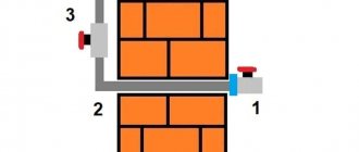
I started with the X axis. Everything turned out to be simpler there than with the other axes. First, we estimate the moves of the table and the place where the moving and stationary parts are secured so that the stationary part is located exactly in the center between the extreme positions of the table. When this place is available, we attach the protection, level with the table, and place the fixed part of the ruler under it, so that it is slightly below the protection and can be slightly moved up and down for adjustment.
Then we roll the table to its extreme positions and mark on the fixed part of the table the installation location of the moving part of the ruler so that it does not reach the edge by 5-10mm. If everything worked out well and there is room for installation, then we simply press the movable part of the ruler against the stationary one and mark points for attaching the movable part of the ruler and the movable part of the table. And then we drill a 4.2-4.3mm drill (you can start with 2mm and gradually expand) and cut an M5 thread there to 15-20mm. The distance between the centers of the holes is approximately 60mm, so you can mark one and mark the second using a ruler.
We should have it so that the stationary part of the ruler, pressed against the moving one, has moves up and down, so that we can more accurately adjust its position after fixing the moving part.
Now we take M5 screws with any head and try to screw them into the thread of the moving part of the ruler so that, after entering the moving part of the table, both of these parts are rigidly fixed to each other and parallel. You can play with the distance, add spacers, or even cut off the threads on the screw like this. so that it just scrolls in the ruler. In general, it's up to you. The main thing is that both parts of the ruler are secured parallel to the movement of the table and to each other. And so that the stroke of the ruler does not end before the stroke of the table, otherwise the table may break the ruler, driving the moving part beyond its stroke.
So, the movable part of the ruler is rigidly screwed to the stationary part of the table; now we adjust the long stationary part of the ruler in the mount so that it is maximally pressed against the movable one and at the same time strictly parallel to the table itself. To do this, you can run the table in both directions and make sure that the distance between the parts of the ruler does not change. In this form, we fix the ruler with screws and attach the protective casing on top.
We attach a ruler to the DRO and watch for changes in the readings on the screen when moving the table. This was the simplest thing.
The other two rulers will have to be secured using brackets, because we have to adhere to the basic rule. The moving part of the ruler should be on the opposite side of the spindle so that splashes from the coolant do not fall on it. Protection must be installed between the ruler and the spindle.
Next, I put a ruler on the Y axis and first made a prototype from angles and 3mm aluminum, which allowed me to quickly twist it all together, so to speak, model it. After connecting, it turned out that the bracket bends a lot and even a small force when moving the ruler is enough for it to warp by 2-3mm.
As a result, I replaced one of the parts of the bracket with a 6mm plate and it became much better.
I struggled with the Z axis already as a scientist and made the entire bracket from 6 and 10 mm plates, so it turned out to be more rigid than on the Y axis.
In both cases, I attached the movable part of the ruler to the bracket with M5 screws, adjusting the distance between them using a thread. In theory, it was also possible to tighten the locking nuts, but I haven’t started doing this yet.
The wires were placed using standard clamps, and the DRO itself was screwed to the machine casing.
Having assembled this miracle, I was happy and remembered that while I was sawing pieces of aluminum plates, some of the chips flew into my face, so I decided to restore the plastic protection.
I was afraid that the “calculator” would get in the way, but in the end everything worked out more than decently.
The time had come to test all this at work and I began to turn the knobs of the dials, zeroing the readings to check the accuracy of the rulers. As it turned out, the accuracy of the rulers was more than good and there 2 decimal places were caught perfectly, and the third was either 0 or 5. And although this was a little annoying, it was a revelation that the horizontal dials not only had large backlashes (which you can try to fix by tightening the nuts and thrust bearings) but also displayed twice the readings. Those. instead of 10 acres, they showed 5. The manufacturer wrote that the accuracy of the dials is 0.02 mm, but at what cost! It turns out that you need to constantly multiply x2?
And I decided to transfer feeds to motors and completely get rid of dials, using electronic ones, which I will try to configure in the driver so that their readings compete with each other. Fortunately, it will be possible to work based on the DRO readings. You just need to deal with the non-rigidity of the Y-axis bracket.
After playing around with the machine, I watched several videos on this topic and was fascinated by this. It turns out that these red plastic guides on the rulers need to be removed, they are for adjustment and transportation. They adjust the distance between the parts of the ruler and after fixing the ruler on the machine, the plastic inserts are removed.
I removed my inserts and immediately the rulers began to move more smoothly, which is especially noticeable on the Y axis and now I’m not sure whether this bracket needs to be redone or whether it will work the way it is for the first time.
While I was climbing inside the DRO I saw a place under the COM port where some kind of chip with wiring should be located.
It would be interesting to see the board with a working COM port, maybe you can configure it yourself in order to then attach the rulers to the CNC as feedback.
Now it's up to automatic feeds and CNC. I hope optical rulers will help me in this matter.