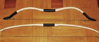
Hello to all DIY lovers! Sometimes during repairs or construction there are such moments that it is necessary to accurately mark the center in one of the workpieces for further cutting or something else. Of course, you can use a regular ruler, calculate everything and measure it out, but if there are a lot of such blanks and each marking takes quite a lot of time, then the repair may take a long time. Actually, I had a similar situation when I made a small decorative fence for a front garden from a picket fence. The picket fence itself was non-standard and 8 cm wide. For a small fence this is too wide and it was decided to saw it lengthwise and make each piece 4 cm long. At first I made the markings with a ruler, which took a lot of time, but then I decided to make a fairly simple one a device for marking the center, with which further work has become much easier and faster.
To make a tool for marking the center of workpieces you will need:
- block (select the length of the block individually to suit your needs);
- pencil (can be replaced with round sticks);
- a simple pencil or felt-tip pen for drawing a line;
- self-tapping screw or bolt.
Read the abstract on everything else: “Marking in plumbing” Page 1
(Back)
The “read” function is used to familiarize yourself with the operation. The markup, tables and pictures of the document may be displayed incorrectly or not in full! “Marking in plumbing”Contents
§ 1. Purpose and technical requirements of markings
§ 2. Geometric constructions when marking § 3. Tools, devices and marking techniques
§ 1. Purpose and technical requirements of markings
Marking is the operation of applying marking marks to the surface of a part or workpiece to be processed, defining the contours of the part profile and the places to be processed. The main purpose of marking is to indicate the boundaries to which the workpiece must be processed. Depending on the shape of the blanks being marked, markings for parts are divided into planar and spatial (volumetric).
Planar marking is carried out on the surface of flat parts, on the surface of flat parts on strip or table material and consists of applying contour and parallel perpendicular lines, circles, arcs, geometric figures according to zonal dimensions or contours of various holes to the workpiece.
Spatial marking is in progress. To mark individual spatial parts located at different angles to each other in different planes, the markings of these individual surfaces are linked to each other.
Devices for planar marking are marking plates, pads, rotating devices, jacks. Tools for spatial marking: scriber, farmers, compasses, marking rod - compass, ruler, squares.
Before marking, you need to do the following: clean the workpiece from dirt, traces of corrosion, carefully inspect the workpiece to identify holes and cracks. Study the drawing and mentally place the marking plan, determine the bases (surface) of the workpiece from which dimensions should be set aside, prepare the surfaces for painting. For painting, various compositions of chalk diluted in water, a solution of copper sulfate (CuSO4), alcohol varnish, and quick-drying varnishes and paints are used.
To save time, simple workpieces are often processed without preliminary marking. For example, in order for a toolmaker to make an ordinary key with flat ends, it is enough to cut off a piece of square steel from a bar of a certain size, and then saw it to the dimensions indicated on the drawing.
Blanks are received for processing in the form of castings (produced from metal poured into pre-prepared molds - earthen, metal, etc.), forgings (produced by forging or stamping), or in the form of rolled material - sheets, rods, etc. (obtained by passing metal between rollers rotating in different directions, having a profile corresponding to the resulting rolled product).
During processing, a certain layer of metal (allowance) is removed from the surface of the workpiece, as a result of which its size and weight are reduced. When manufacturing a part, its dimensions are laid down on the workpiece exactly according to the drawing and marked with lines (marks) indicating the processing boundaries to which the metal layer should be removed.
Marking is used mainly in single and small-scale production.
At large-scale factories and... mass production, the need for markings disappears due to the use of special jigs, stops, etc. Three main groups of markings are used:
What is a marking operation?
It should be immediately clear that marking does not necessarily mean fixing the distance from one point to another when constructing a particular structure. As production and construction standards become more complex, the manufacturability of marking processes also increases. During this action, a foreman at a construction site or an operator on a production line can determine the parameters of the workpiece, the characteristics of its location relative to other objects, etc. A modern marking tool allows you to record indicators such as length, width, height and angle. Some models such as squares are also focused on initially determining how well an object, its parameters or location meet the requirements. As for the marking process, it mainly involves manual handling of measuring and marking devices. The user, in turn, is required to be attentive, accurate and thorough in removing and recording data.
Spatial marking tool
Categories
If it is necessary to punch the center holes at the ends of the shafts, it is convenient to use a special device for punching - a bell (Fig. 2.6, o). This device allows you to apply core recesses on the centers of the end surfaces of shafts without preliminary marking them.
For the same purposes, you can use a center finder square (Fig. 2.6, b, c), consisting of a square 1 with a ruler 2 attached to it, the edge of which divides the right angle in half. To determine the center, the tool is placed on the end of the part so that the internal flanges of the square touch its cylindrical surface and a line is drawn along the ruler with a scriber. Then the center finder is turned to an arbitrary angle and a second mark is made. The intersection of the lines marked on the end of the part will determine the position of its center.
Quite often, to find centers at the ends of cylindrical parts, a center finder-protractor is used (Fig. 2.6, d), which consists of a ruler 2 attached to a square 3. The protractor 4 can be moved along the ruler 2 and fixed in the desired position using a locking screw 1. The protractor is placed on the end surface of the shaft so that the side flanges of the square touch the cylindrical surface of the shaft. The ruler passes through the center of the shaft end. By installing the protractor in two positions at the intersection of the marks, the center of the shaft end is determined. If you need to make a hole located at a certain distance from the center of the shaft and at a certain angle, use a protractor, moving it relative to the ruler by a given amount and turning it to the required angle. At the point of intersection of the ruler and the base of the protractor, the center of the future hole is punched, which is offset relative to the axis of the shaft.
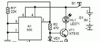
The punching process can be simplified by using an automatic mechanical punch (Fig. 2.7), consisting of a body assembled from three parts: 3, 5, 6. The body contains two springs 7 and 11, a rod 2 with a punch 1, a hammer 8 with a shifting block 10 and a flat spring 4. Punching is carried out by pressing the tip of the punch on the workpiece, while the inner end of the rod 2 rests against the block, as a result of which the striker moves upward and compresses the spring 7. Resting against the edge of the shoulder 9, the block moves to the side and its edge comes off the rod 2. At this moment, the striker, under the force of a compressed spring, delivers a strong blow to the end of the rod with the center punch, after which spring 11 restores the normal position of the center punch. The use of such a core punch does not require the use of a special impact tool - a hammer, which greatly simplifies the work of applying core recesses.
How to mark a parking lot
In open and closed parking lots, there must be strict designation of parking spaces, pedestrian crossings, and navigation arrows. Additionally, columns are painted and parking spaces are numbered. All marking principles are standardized by GOST 52289-2004, especially places for people with disabilities.
Standard parameters of a parking space: length - 5 m, width - 2.5 m, 3.6 m - for disabled people . The width of the passage is taken into account - 6 m, the width of the marking lines - 10 cm.
For such work, it is recommended to use road paints, cold or hot plastic, epoxy, and polyurethane paints. Preliminary preparation, measurements and calculation of parking spaces are carried out, taking into account the total area, number of parking spaces, fences and the capabilities of the territory. The coating must be thoroughly cleaned of debris and dirt.
The selected material is applied using special equipment, in rare cases manually . A mandatory condition is to fence the locations of fire extinguishers, exits, and fire hydrants with reflective paints and tapes.
Spatial marking
For spatial marking of cylindrical workpieces, a special prism has been developed, in which the arc of the clamp does not protrude beyond the edges of the prism. This makes it possible to periodically rotate the prism with the workpiece and simultaneously mark horizontal and vertical marks or check cylindrical and square surfaces.
There are planar and spatial markings. The permissible deviations from the perpendicularity of the side surfaces are also standardized.
There are flat and spatial markings.
In spatial marking, horizontal lines are conventionally called marks (for example, a and b) formed by the intersection of planes a and P, parallel to the marking plate, when the part is first installed.
When marking in space, treated surfaces are taken as bases, and if they are absent, the surface that will not be processed is taken as bases.
When marking spatially, work begins with drawing the main center and axial lines, and from them all other lines are drawn in accordance with the dimensions indicated on the drawing. First, all the horizontal lines are drawn, then all the vertical ones, after which the inclined lines are drawn and, finally, circles and roundings. In this case, the dimensions must be taken according to the scale ruler in accordance with the dimensional numbers in the drawing. You cannot take the size directly from the drawing, since the image of the part in the drawing can be made to scale.
| Vertical measuring ruler. |
For spatial marking, a surface planer is widely used. They apply horizontal marks, and after re-edging the parts, vertical marks are applied, and the correct installation of the part on the slab is checked with a thicknesser.
When marking spatially, the correct relative position of the surfaces must be ensured.
When marking in space, treated surfaces are taken as bases, and if they are absent, the surface that will not be processed is taken as bases.
| Marking the hole. |
When spatially marking workpieces, it is necessary to apply horizontal, vertical and inclined marks. These mark names are retained even when the workpiece is rotated during the marking process. If, for example, the marks in the initial position of the workpiece were drawn horizontally, then, although they became vertical when the workpiece was turned by 90, so as to avoid confusion, they continue to be called horizontal.
When spatially marking workpieces, it is necessary to apply horizontal, vertical and inclined marks. These mark names are retained even after the workpiece is rotated during the marking process. If, for example, the marks were drawn horizontally when the workpiece was initially laid out, then although they became vertical after turning the workpiece by 90 degrees, so as to avoid confusion, they continue to be called horizontal.
For precise spatial markings, the method of rotating the part and installing it in several positions is often used. To be sure that the rotation of the part by 90 will be done correctly, the two mutually perpendicular sides of the marked part are carefully processed and adjusted to precise markings using a straight edge and a square. These two sides further serve as the basis for precise marking and all further processing. Designers designing a part select such surfaces in advance and set all dimensions (coordinates) from them. These surfaces must be treated especially carefully.
When marking spatially, parts are usually marked in several positions, and they are installed on the marking plate not in an arbitrary position, but so that most of the marks that need to be marked on the part, and, in particular, one of the main axes of symmetry of the part (if any) ), was parallel to the plane of the marking plate.
How to use the tool
We attach the homemade product to the workpiece (for example, it will be a 40x40 mm professional pipe). We place the marker in the hole we need and draw a quarter circle.
We move the tool in accordance with the arrow, and put a point in the right place. We move the tool and draw a straight line.
After this, mark the area that needs to be cut with a cross and cut it out with a grinder.
Similar markings must be made on the opposite side of the workpiece.
After this, we simply bend the profile pipe and weld the seams. As you can see, there is nothing difficult if you make markings with this tool.
Stage 6. Chopping
Chopping is a roughing step for preparing a part for processing.
This process is used for metalworking work where precision processing is not required, for example, for cutting off protrusions, grooves or rough alignment. Metal chopping is performed using a tool steel chisel, a cross-cutting tool for notching, and a hand or pneumatic hammer.
The part is clamped in a vice so that the cutting line is level with the clamping jaws. The chisel is tilted at an angle of 30–35° and hit with a hammer. If it is necessary to cut down a thick layer of metal, the cutting is carried out in several passes.
If the workpiece is copper or aluminum, apply soapy water or oil to the chisel blade. Brittle metals such as cast iron and bronze are chipped when chopping, so first chamfers are applied to the edges of the part to facilitate the passage of the chisel.
Main stages of work
From a metal strip (or from sheet metal) we cut two blanks of the same length. Then we cut off a piece of the corner. We weld the support “legs” to it.
Next, we cut off a ring from a round steel pipe and cut out part of the wall in it to the width of the corner. We weld this part to the corner, as shown in the photo below.
In the center of the welded part, we drill a hole for the diameter of the threaded rod, which will act as a clamp. A guide nut must be welded over the hole.
At the next stage, screw the threaded rod into the guide nut and screw on the wing nut. We weld a piece of metal strip at the end of the corner.
Micrometer
A measuring instrument of this type is designed to make fairly accurate measurements of small linear dimensions. The maximum measurement limit of modern micrometers reaches 600 millimeters, and the accuracy is 0.01 millimeters.
Micrometers (as, indeed, all micrometric instruments) are equipped with special reading units based on a screw pair with a thread pitch of 0.5 millimeters. With its help, the longitudinal movement of the measuring screw is converted into circumferential movements made by the drum scale. It is on the basis of the angle of its rotation that the value of the measured size is determined.
Spatial marking
Spatial marking is the marking of workpiece (part) surfaces located in different planes and at different angles, carried out from any initial surface or marking line chosen as the base.
Spatial marking, the most common in mechanical engineering, differs significantly in its techniques from planar marking. The difficulty of spatial marking lies in the fact that you have to not just mark the individual surfaces of the part. Spatial marking, as a rule, is carried out on a marking plate, which is an artificial plane with the help of which the specified alignment is achieved.
Spatial marking, the most common in mechanical engineering, differs significantly in its techniques from planar marking. The difficulty of spatial marking lies in the fact that it is necessary not only to mark individual surfaces of a part located in different planes and at different angles to each other, but to link the markings of these individual surfaces with each other. Spatial marking, as a rule, is carried out on a marking plate, which is an artificial plane with the help of which the specified alignment is achieved.
| Spatial marking (the blank of the corner lever is marked. |
Spatial marking (Fig. 22) is the marking of workpiece surfaces located in different planes at different angles to each other (see Ch.
Spatial marking is the marking of workpiece surfaces (Fig. 174, b), located in different planes and at different angles to each other.
Spatial marking is used for graphic constructions carried out on the surface of volumetric workpieces located in different planes at different angles to each other. When marking spatially, it is necessary not only to mark individual elements on one surface (side) of a part, but to link the markings of these surfaces (planes, axes of holes in their alignment, angles of inclination) with each other.
Spatial marking is used for graphic constructions carried out using spatial kinematic chains.
Spatial marking is sometimes called volumetric marking.
| Scheme of markings on the floor of a press column forging. |
Spatial marking errors are caused by the simultaneous action of the following reasons: an error in the angular installation of the marked installation; error in setting the height gauge and its deviations when moving along the marking plate; the use of imperfect marking methods; inaccuracy of geometric constructions; inaccuracy of marking tools and devices.
Spatial marking techniques differ significantly from planar marking techniques. The peculiarity of spatial marking is that it is necessary not only to mark individual surfaces of the workpiece located in different planes and at different angles to one another, but to link the markings of these surfaces to each other. Spatial marking is usually done on a marking plate. By properly placing the part on the plate and linking the markings of each plane of the part with the common plane of the marking plate, the markings of the individual planes are thereby linked to each other.
| Devices used for installing and securing workpieces on a marking plate. a – prisms. b – square ] c – marking box d – cli. woven linings. d – jack |
For spatial marking, the following tools are used: a metal measuring ruler, a vertical measuring ruler with a stand, checking and marking squares, a scriber, a surface gauge, a height gauge, a compass, center punches and a hammer. These tools are described in Chap.
The difference between spatial marking and planar marking is that the marking of individual workpiece surfaces is linked to previously marked surfaces by orienting the marking tool and the workpiece relative to each other using a marking plate.
How to mark in a warehouse
In warehouse complexes and other industrial premises, markings serve to prevent any actions and draw attention to dangerous areas. The main types of markings are arrows, lines, signs, shading.
In order to improve logistics processes and ensure safety in warehouses, the following is used:
- marking areas of movement of equipment and personnel. In this case, pedestrian zebra crossings, arrows, signs, boundary lines are actively used, and shelving is outlined;
- marking of floor storage cells with codes, shading, alphanumeric numbering.
Stage 5. Chamfering
Chamfering is necessary if the edge of a part needs to be prepared for a strong and reliable connection, for example for welding.
A chamfer is a bevel of the end of a part. Sliced in two ways:
- Thermal. Using gas or plasma cutters. The chamfer turns out clean and even.
- Mechanical. The chamfer is removed using edge milling machines or chamfer removers.
The first method is fast and inexpensive, but when processing chamfers, the metal heats up, which can lead to its deformation and destruction of the structure. The second method does not have a temperature effect on the metal, however, mechanical chamfering is a more labor-intensive and time-consuming process.
We cut the pipe at an angle of 90 degrees
To mark the cut [of water and gas pipes] at a right angle, you can use a sheet of standard A4 paper, wide electrical tape or construction tape. If you wrap a wide enough material around the pipe so that the edges line up exactly when applied, you will get a perfect cutting line. If the tape or tape is firmly stuck to the metal, you can go right along the edge.
It is important to be able to use the grinder correctly, hold it with a certain force and follow safety rules. The technique described is the simplest; it is also suitable for cutting a large diameter pipe.
Hole marking
Marking center holes is one of the most difficult operations in metalworking, which is associated with high precision. Several tools are used for these purposes. Most often this is a marking compass and a center finder.
Compasses are used in cases where there is no need to maintain high accuracy.
The techniques and their sequence are as follows:
- The legs of the compass are moved apart to a distance equal to the radius of the workpiece.
- then, resting one leg against the edges of the workpiece, a stroke is applied;
- repeat this at least 4 times from different sides so that a quadrangle is formed in the center, the center of which is the center of the workpiece, and is marked by eye;
- then a hole is made using a center punch.
A center finder is a simple but highly accurate tool. With its help, only two perpendicular lines are drawn, the transfer of which is the center of the workpiece.
When using, it is important to hold the center punch vertically; even the slightest deviation from the axis will affect the accuracy of the mark. In some cases, the surface of the workpiece can be covered with chalk in order to better see the inscribed marks on these surfaces
In some cases, the surface of the workpiece can be covered with chalk in order to better see the inscribed marks on these surfaces.
How the homemade product works
Install the device on a flat surface. Place the workpiece inside the corner and press it with a threaded rod.
Using a marker, place two marks on the end of the pipe (bottom and top).
After this, all that remains is to attach something even (a square or a piece of corner) to the marked marks and draw lines.
Marriage during marking
First of all, when marking, defects that were made at previous stages of production emerge. Products from procurement sites or workshops, as well as materials purchased from other enterprises, reveal:
- violation of dimensions
- shape distortion
- warping.
Such castings or rentals are not subject to further marking operations, but are returned to the department or organization that caused the defect to correct it.
At the marking stage itself, defects can be caused by the following factors:
- Inaccurate drawing. The mechanic, without hesitation, displays incorrect dimensions on the part, and during further processing, defective products come out.
- Inaccuracy or malfunction of instruments. All marking tools are subject to mandatory periodic verification by the metrological service of the enterprise or an authorized metrological center.
- Incorrect use of tools or marking accessories. There are known cases when instead of calibrated measuring pads, ordinary pads were used to set the level. In this case, erroneous application of angles and slopes is also possible.
- Inaccurate placement of the workpiece on the marking table or plaza. They lead to distortions when setting aside dimensions, violation of parallelism and coaxiality.
- Wrong choice of reference planes. It is also possible that some of the dimensions were applied from the base planes, and some from the rough surfaces of the workpiece.
Marriage during marking
Separately among the reasons for defects are the marker's errors. These include:
- Incorrectly read drawing. It is possible to apply a radius instead of a diameter and vice versa, inaccurate application of the centers of holes relative to the center marks, etc. If any difficulties arise, the mechanic must seek clarification from the foreman or foreman.
- Carelessness and inattention when punching and drawing lines.
Negligence can be committed by both the mechanic himself and his supervisors, who did not check the tool on time or issued inappropriate marking devices.
Typically, marking operations are entrusted to the most experienced and responsible workers, counting on the fact that they will not mechanically transfer dimensions from the drawing to the workpiece, but will treat the matter thoughtfully and promptly notice and eliminate the reasons for possible defects on their own or by contacting their managers.
If you find an error, please select a piece of text and press Ctrl+Enter.
Marking devices
One of the different types of devices for marking parts is scribers. These are pointed rods used for applying marks. This bench marking tool is used with guide tools. There are several types of scribers, among which the following three are the most common. Round options are represented by rods with one hardened and pointed end and the other bent into a ring. Tools with a bent end are sharpened on both sides, and one of the ends is bent perpendicular to the rod. In addition, the middle part is thickened. These scribers are designed for marking hard-to-reach areas. Models with an insert needle are similar in design to watch screwdrivers.
Gauge gauges are designed for drawing parallel lines and checking the installation of the workpiece during spatial marking. This device is represented by a scriber mounted on a stand with a base. The latter can be placed on the rack in any way. For precision work, use a height gauge with a scale. For conventional options, scale rulers or gauge blocks are used to increase accuracy.
Marking compasses are designed to transfer linear dimensions to a workpiece, create circles for curved parts such as propellers, divide angles and segments, and measure. These products, used for marking, are presented in regular and spring versions. The former have the ability to fix the legs to size, while the latter allow for precise installation. In any case, they are equipped with an arc and a screw for fixing the legs. The latter are sharpened and their ends touch, and the needles are hardened over 15-25 mm. Like scribers, compasses are tools for planar marking.
A marking caliper is designed for particularly precise marking and drawing of large circles. It differs from the usual one by the presence of a micrometric screw. Includes a ruler with two legs equipped with hardened, replaceable needles. The movable leg is equipped with a vernier, and its needle moves along the scale, providing the ability to draw circles in various vertical planes.
Tools for marking metal were discussed above.
The drawbar is designed for marking wooden parts by applying marks to their edges. It is represented by a wooden block 40x5 cm. At one end of it, 1/5 in size, there is a movable scriber in the form of a needle, a sharp pin or a nail. The remaining part of the bar has a thickness of 5-7 mm less.
The bracket is designed for marking when creating eyes and tenons. This is a wooden block with a recess of 1/4 at a distance of 1/3 from the edge with nails located at a mutual distance equal to the thickness of the eyes or tenons.
Marking devices
Based on the difficulties of performing spatial markings, many tools and devices have been developed for its application. Moreover, most of these tools are suitable for application and planar marking.
Among the most common devices for spatial marking are:
- A scriber is the simplest and most versatile tool that does not require special training and allows you to apply markings in the field. Most often, it is a metal rod, one end of which is pointed. Typically, carbon steels of various grades are used for their manufacture. Either one or two ends can be sharpened, depending on the purpose of the tool. Their length is usually about 10 cm. Often, in order to prevent the end from becoming dull, it can be additionally hardened. Sketchers are usually used with rulers or templates.
- Reismas - the basis of the reismas is the devil, but it has a more complex design, as it is used for applying strokes on a vertical surface. It usually consists of a vertical post with metric markings applied, and a parallel post with a fixed scriber. This tool is used when it is necessary to apply high-precision markings.
- A compass is an indispensable tool necessary for drawing circles, arcs, as well as dividing segments into separate equal parts. There are two types: simple and spring. Simple ones will allow you to fix the legs in a certain position, measuring and selecting segments of the required length. Spring compasses are less common, but more accurate. Also highlight such a variety as marking calipers.
- A center punch is a metalworking tool in the form of a rod. It is used to make core recesses necessary for dividing circles into equal parts. One of its sides is pointed, a hole is made with it, and the other is flat, on which a blow is made with a hammer. The resulting hole makes working with the drill easier; it does not slip and is located exactly in the center.
The punch is usually made of partially hardened high-strength steel. The sharpened rod is subjected to hardening. Such a tool usually has a size from 10 to 18 cm.
There is also an automatic model of such a tool, which greatly simplifies working with it.
You don't need to hit it with a hammer to make a hole. The most common of these is electric. It is based on a coil with a rod inside. When you press the tip, the circuit closes, a magnetic field appears in the coil, under the influence of which the rod hits the surface, creating a depression.
- A marking plate is a cast iron surface on which parts and tools for marking are installed. It should not lose shape, bend or bend during operation. Grooves can be made on the slab, forming equal squares. These grooves make it easier to install tools. Can be produced together with a stand or installed on a desktop.
- Prism – is a stand with a prismatic recess. It consists of two prism-shaped cheeks, between which the workpiece is installed. Can be installed on a screw support. With its help, you can adjust the position of the cheeks, increasing or decreasing the distance between them.
- Square with a shelf - most often used for planar markings, but can also be used for spatial markings. It is used in cases where there is a need for a precise positioning of the workpiece in the marking device.
- Marking wedges - used to adjust the installation height of an object with minimal deviations.
- Jacks are analogues of wedges, and also allow you to accurately adjust the height. The jack must be used in cases where the work involves massive workpieces.
Paint is used as an additional device for marking work. The surface is covered with it so that the marking strokes are clearly visible. It is selected in such a way that it contrasts well with the natural surface, even in dim lighting.