At the end of the USSR, domestic semiconductor televisions of the USCT series appeared and were very popular, some of them are still in service. TVs with a screen size of 51 cm diagonally were especially durable (the kinescope was very reliable). Of course, they no longer meet modern requirements at all, but as a “dacha option” they are still quite suitable.
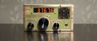
Somehow, out of nothing to do, a desire arose to improve the old, already “dacha” “Raduga-51ТЦ315”, adding a remote control system to it. Now it is impossible to purchase a “native” module, so it was decided to make a simplified single-command system that allows at least switching programs “in a ring”. Microcontrollers and special microcircuits were immediately rejected due to unprofitability, and the system was made from what was available.
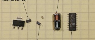
Namely, integrated timer 555, IR LED LD271, integrated photodetector TSOP4838, counter K561IE9 and plus some other little things.
Control panel diagram
The remote control is a pulse generator with a frequency of 38 kHz, at the output of which an infrared LED is switched on via a key. The generator is built on the basis of the “555” microcircuit, the so-called “integrated timer”. The generation frequency depends on the C1-R1 circuit; when setting up, by selecting resistor R1, you need to set the frequency at the output of the microcircuit (pin 3) to 38 kHz.
Fig.1. Schematic diagram of an IR transmitter for remote control of a TV.
Rectangular pulses with a frequency of 38 kHz are supplied to the base of transistor VT1 through resistor R2. Diodes VD1 and VD2 together with resistor R3 form a current control circuit through the IR LED HL1.
With increased current, the voltage on R3 increases, and the voltage on the emitter VT1 increases accordingly. And when the voltage at the emitter approaches the drop voltage across the diodes VD1 and VD2, the voltage at the base of VT1 decreases relative to the emitter, and the transistor closes.
Pulses of IR light, following with a frequency of 38 kHz, are emitted by the HL1 infrared LED.
Control is by one button S1, which supplies power to the remote control circuit. While the button is pressed by the remote control, infrared pulses are emitted.
What you need to know about the infrared spectrum?
The infrared spectrum is a small part of electromagnetic radiation that, unfortunately, our eyes cannot see. The wavelength of infrared radiation is longer than the wavelength of red light, i.e., it has a lower frequency.
| Hence the name - infrared means to be under the red. |
Electromagnetic spectrum - division by wavelength
Infrared waves are between microwaves and visible light, and this is a very wide range. For this reason they have been divided into three main groups:
- near infrared - from 700 nm to 1 micron,
- short or medium infrared - from 1 micron to 15 microns,
- far infrared - from 15 microns to 1 mm.
Division into visible light and infrared
In the near and mid-infrared region, optical fibers are used to transmit data over long distances. Long infrared radiation and its far part are used for “heat transfer” - such light is used, for example, in infrared heaters.
Receiving block diagram
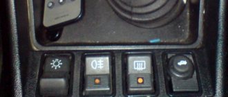
The receiver is installed inside the TV, it is supplied with + 12V power from the TV's power supply, and the cathodes of the VD2-VD9 diodes are connected to the contacts of the buttons of the USU-1-10 program selection module.
Fig.2. Schematic diagram of an IR receiver for remote control of a TV.
IR pulses emitted by the remote control are received by an integrated photodetector HF1 type TSOP4838. This photodetector is widely used in remote control systems for various household electronic equipment. When a signal is received, there is a logical zero at its pin 1, and a logical one when there is no received signal.
Thus, when the remote control button is pressed, its output is zero, and when not pressed, its output is one.
TSOP4838 should be powered by a voltage of 4.5-5.5V, and no more. But, to control the TV program selection module, you need to apply 12V voltage to the buttons of the transistor 8-phase trigger. Therefore, a voltage of 12V is supplied to the D1 chip, and a voltage of 4.7-5V is supplied to the photodetector HF1 through a parametric stabilizer on the zener diode VD10 and resistor R4.
Transistor VT1 serves as a cascade matching the levels of logical units. In doing so, it inverts the logic levels. The voltage from the collector VT1 through the circuit R3-C2 is supplied to the counting input of the counter D1, designed to receive positive pulses. The R3-C2 circuit is used to suppress errors from bouncing contacts of the S1 button on the control panel.
Counter D1 K561IE9 is a three-digit binary counter, with a decimal decoder circuit at the output. It can be in one of eight states from 0 to 7, while a logical one is present at only one output corresponding to its state. The remaining outputs are zeros.
Each time you press or release the remote control button, the counter moves one state up, and the logical unit of its outputs switches. If the countdown started from zero, then after eight presses of the button, on the ninth, the counter will return to the zero position. And then, the process of switching the logical unit along its outputs will be repeated.
The LD271 IR LED can be replaced with any IR LED suitable for household appliance remote controls. The TSOP4838 photodetector can be replaced with any complete or functional analogue.
Useful tips
In infrared devices with beam transmission and reception, the receiver and transmitter are usually performed as autonomous units, although in most cases they at least have a common power source, or are even located next to each other.
Therefore, if you add just one synchronization wire to the two wires going to the receiver from a common power source with the transmitter, you can get a wonderful device. It will operate on the principle of a synchronous detector and have such properties as: selectivity; noise immunity; possibility of obtaining large gain.
And this is without the use of multistage amplifiers with complex filters.
Indoors, even without the use of additional optics and powerful emitters, the device can be used as a security alarm, triggered when an infrared beam crosses at a distance from the emitter to the receiver of 3-7 m.
Moreover, the device does not respond to external illumination from extraneous sources, both constant (sun, incandescent lamps) and modulated (fluorescent lighting, flashlight).
By equipping the receiver's LED with a collecting lens, you can cover several tens of meters of distance in open space, having excellent noise immunity even when there is light snow. By using lenses on the receiver and transmitter simultaneously, it is possible to cover even greater distances, but there is the problem of accurately aiming the narrow transmitter beam at the receiver lens.
What is the 1N4148 diode used for?
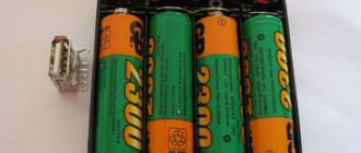
A 1N4148 diode connected in series with the power supply reduces the battery voltage by approximately 0.7 V. This was necessary because the manufacturer does not allow the receiver to be powered with a voltage higher than 5.5 V. In the block, four new 1.5 V batteries provide voltage 6 V or slightly higher). So we had to somehow “reduce” the tension. One rectifier diode (actually the voltage drop that it creates) is enough. Thanks to this procedure, we did not have to use a voltage stabilizer or a switching converter.
What can serve as an IR transmitter?
Most often, special LEDs or lasers are used for transmission. For our tasks, that is, transmission over short distances through the air, IR LEDs are used, that is, those that emit infrared light . They are cheap, compact and easy to use.
Transmitting (IR) diodes work in the same way as the regular LEDs we covered in our earlier articles. The only difference is the “crystal” that emits light. Of course, all this is done to ensure that it has the correct wavelength. In addition, thanks to the properties of the human eye, the operation of this diode is invisible to us.
IR LEDs most often come in two versions: with a clear or dark (black / dark blue) lens. The color of the lens does not matter at all; a dark lens is not an obstacle to infrared radiation. In addition, like regular LEDs, they are available in packages of different diameters, for example 3 and 5 mm.
Various colors of IR LED lenses
Specific information about the IR diode is contained in the manufacturer's documentation, which can be found by looking at the diode symbol - unfortunately, it is not marked anywhere on the case. It is worth looking for the designation on the seller's website, although it is not always indicated.
In the case of LEDs of this type, it is worth checking such parameters as:
- emitted wavelength,
- maximum continuous power,
- maximum continuous current (of the order of several tens of milliamps),
- maximum current per pulse (even more than 2 amperes),
- operating voltage,
- lighting angle,
- case size.
The practical use of transmission diodes differs from LEDs in that they are usually pulse powered. Transmission occurs by blinking at a frequency of several tens of kilohertz pulses with a filling of only a few percent. Simply put, instead of constantly lighting, we flash the diode very quickly - so that the glow time is much shorter than when the diode is off.
| Of course, we're talking about an automatically generated signal that "blinks" the LED very, very quickly (e.g. 36,000 times per second) - we'll get into that later in this article. |
Thanks to this, this element will not have time to overheat when powered by a higher current. In practice, we receive short but very strong light pulses, which are enough to transmit data over a distance. This is why the TV remote has such a good range - a strong beam of light is easily reflected, for example, from walls and ceilings and hits the receiver.
Example of IR diode control
The parameters of an example IR diode might look like this:
- wavelength: 940 nm,
- maximum continuous power: 100 mW,
- maximum continuous current: 20 mA,
- forward voltage: 1.6 V,
- beam angle: 20°,
- case size: 5 mm.
Read also: Operation of chokes and their use
Based on the information in the article describing what power is, you can quickly calculate that connecting a diode to a constant power source will allow current to pass through it no more than:
I max = P max / U f = 100 mW / 1.6 V = 62.5 mA
However, these are theoretical values because in this case 100 mW is the maximum power that can be emitted from this diode (taking into account, for example, the strength of the legs, the structure of the diode and its connections). It does not have to coincide with other maximum diode parameters. You should always carefully study the catalog notes for a particular item.
As we already mentioned, transmission diodes are designed for pulsed operation, unlike the previously discussed diodes, which usually operate in continuous mode. Let's assume the duty cycle is 10%, which is a typical value.
| This means the LED is on 10% of the time and off 90% of the time. |
Then the permissible current in the pulse will be:
I max_imp = P max / (U f ⋅ kf ) = 100 mW / (1.6 V 10%) = 625 mA
Higher current means higher light intensity. We want our TV remote to work from almost anywhere in the room.
Such calculations should be considered approximate, since accurate calculations require a current-voltage characteristic, which few manufacturers provide in their documentation. However, in practice, such an assessment is often sufficient.
Conclusion
The infrared port, despite its ease of use and low cost of transceiver components, has a serious drawback: it requires the transmitter and receiver to be visible (it is impossible to transmit information, for example, through a wall). This is one of the reasons for abandoning the IrDA infrared data transmission scheme. It has been replaced by technologies that use radio waves (including Bluetooth and Wi-Fi).
However, when there are no obstacles, infrared still has many uses, so know that! Moreover, one of its advantages is the ability to bounce off walls. Thanks to this property, the infrared port can be used, for example, to build an obstacle sensor.
Sincerely, MonitorBank
Integrated infrared receivers
There are two main groups of infrared-sensitive elements on the market: photodiodes and phototransistors . The interesting thing is that both of these elements usually look the same as regular LEDs. So be careful not to confuse them, as it is almost impossible to distinguish them visually.
However, the use of these basic elements when implementing the transmission path is quite difficult due to interference from the environment. Therefore, manufacturers of electronic components have created so-called integrated infrared receivers. The TSOP family of receivers are items that almost every electronics engineer has encountered. One of them is located in the TSOP31236 .
TSOP31236 - infrared receiver
Integrated infrared receivers have special, completely enclosed, opaque housings, but infrared radiation penetrates without problems through such a housing. This is one of the treatments that makes this element resistant to interference.
Inside this infrared receiver is a rather complex circuitry responsible for receiving, filtering and decoding the signal. Below is a block diagram from the technical documentation showing (more or less) what is contained in this element.
Block diagram of TSOP31236
Fortunately, we don't need to go into the details of its structure—the curious will find a description of these blocks later in this article. Now, it's worth noting that on the inside we have a receiving diode (which is indicated by arrows leading to the diode, not on the outside as with light-emitting diodes), a transistor, and a series of "circuits" that decode the signal and check that it is correct.