My friend asked me to build a simple radio for him with his own hands in a certain theme. He looked at several options I suggested, and we agreed on the theme of Guinness beer.
Guinness is an Irish draft beer, its emblem is a golden harp. We decided that the central place in the design of the radio would be given to this harp, and we decided to omit the text.
After drawing several sketches, we came to the conclusion that the most successful shape was the “tombstone” shape. Having chosen a shape, we began to design and assemble a vintage MP3 radio.
One of the main tasks was the built-in subwoofer. I used the speakers from 2.1 computer speakers, I ordered the MP3 module on eBay.
List of materials used for a homemade radio:
- computer speakers 2.1
- power supply 12V 1A AC-DC (for MP3 module) - step-down converter
- mp3 decoder
- rotary switch (for lamps)
- FM antenna (built into the MP3 module)
- gold caps for volume, bass and power switches
- gold foil and glue
- double-sided foam adhesive tape, wires and various auxiliary materials
Files
- Guinness Radio - Simplicity.mp4
How to make a radio receiver with your own hands?
A do-it-yourself radio receiver includes an antenna, a radio board and a device for reproducing the received signal - a loudspeaker or headphones. The power supply can be either external or built-in. The scale of the received range is in kilohertz or megahertz. Radio broadcasting uses only kilohertz and megahertz frequencies.
Basic manufacturing rules
A home-made receiver must be mobile or portable. Soviet VEF Sigma and Ural-Auto radios, and the more modern Manbo S-202 are examples of this.
The receiver contains a minimum of radio elements. These are several transistors or one microcircuit, without taking into account the attached parts in the circuit. They don't have to be expensive. A broadcast receiver that costs a million rubles is almost a fantasy: this is not a professional walkie-talkie for the military and special services. The quality of reception should be acceptable - without unnecessary noise, with the ability to listen to the whole world on the HF band while traveling across countries, and on VHF - to move tens of kilometers away from the transmitter.
You need a scale (or at least a marking on the tuning knob) that allows you to estimate which range and frequency you are listening to. Many radio stations remind listeners what frequency they are broadcasting on. But repeating 100 times a day, for example, “Europe Plus”, “Moscow 106.2” is no longer in fashion.
The receiver must be dust- and moisture-proof. This will provide a housing, for example, from a powerful speaker that has rubber inserts. You can also make such a case yourself, but it is hermetically sealed on almost all sides.
Construction of the building
To make the body, several planks were cut from a sheet of treated fiberboard 3mm thick with the following dimensions: - front panel measuring 210mm by 160mm; - two side walls measuring 154mm by 130mm; — upper and lower walls measuring 210mm by 130mm; — rear wall measuring 214mm by 154mm; — boards for attaching the receiver scale measuring 200mm by 150mm and 200mm by 100mm.
The box is glued together using wooden blocks using PVA glue. After the glue has completely dried, the edges and corners of the box are sanded to a semicircular state. Irregularities and flaws are puttied. The walls of the box are sanded and the edges and corners are sanded again. If necessary, putty again and sand the box until a smooth surface is obtained. We cut out the scale window marked on the front panel with a finishing jigsaw file. Using an electric drill, holes were drilled for the volume control, tuning knob and range switching. We also grind the edges of the resulting hole. We cover the finished box with primer (automotive primer in aerosol packaging) in several layers until completely dry and smooth out the unevenness with emery cloth. We also paint the receiver box with automotive enamel. We cut out the scale window glass from thin plexiglass and carefully glue it to the inside of the front panel. Finally, we try on the back wall and install the necessary connectors on it. We attach plastic legs to the bottom using double tape. Operating experience has shown that for reliability, the legs must either be firmly glued or fastened with screws to the bottom.
Holes for handles
Tools and materials
Will be required as consumables.
- A set of radio components - the list is compiled according to the selected scheme. You need resistors, capacitors, high-frequency diodes, homemade inductors (or inductors instead), low- and medium-power RF transistors. Assembly on microcircuits will make the device small-sized - smaller than a smartphone, which cannot be said about the transistor model. In the latter case, you will need a standard 3.5 mm headphone jack.
- A dielectric plate for a printed circuit board is made from scrap materials that do not conduct current.
- Screws with nuts and lock washers.
- The case is from an old speaker, for example. The wooden case is made of plywood - it will also require furniture corners.
- Antenna. Telescopic (it’s better to use a ready-made one), but a piece of insulated wire will do. Magnetic - wound on a ferrite core independently.
- Winding wire of two different sections. The magnetic antenna is wound with a thin wire, and the coils of the oscillating circuits are wound with a thick wire.
- Power cord.
- Transformer, diode bridge and stabilizer on a microcircuit - when powered from mains voltage. To be powered by batteries the size of a regular battery, a built-in power adapter is not needed.
- Wires for indoor installation.
Tools:
- pliers;
- side cutters;
- a set of screwdrivers for minor repairs;
- wood hacksaw;
- hand jigsaw.
You will also need a soldering iron, as well as a stand for it, solder, rosin and soldering flux.
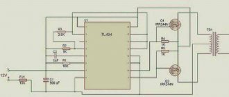
Electrical circuit of the radio receiver
prototyping did not work for me. During the debugging process, I abandoned the reflex circuit. With one HF transistor and a ULF circuit repeated as in the original, the receiver started working 10 km from the transmitting center. Experiments with powering the receiver with a low voltage, like an earth battery (0.5 Volts), showed that the amplifiers were insufficiently powerful for loudspeaker reception. It was decided to increase the voltage to 0.8-2.0 Volts. The result was positive. This receiver circuit was soldered and, in a two-band version, installed at a dacha 150 km from the transmitting center. With a connected external stationary antenna 12 meters long, the receiver installed on the veranda completely sounded the room. But when the air temperature dropped with the onset of autumn and frost, the receiver went into self-excitation mode, which forced the device to be adjusted depending on the air temperature in the room. I had to study the theory and make changes to the scheme. Now the receiver worked stably down to a temperature of -15C. The price for stable operation is a reduction in efficiency by almost half, due to an increase in the quiescent currents of transistors. Due to the lack of constant broadcasting, I abandoned the DV band. This single-band version of the circuit is shown in the photograph.
How to assemble a simple radio receiver?
There are several radio receiver circuits:
- detector;
- direct amplification;
- (super) heterodyne;
- on a frequency synthesizer.
Receivers with double and triple conversion (2 or 3 local oscillators in a circuit) are used for professional work at the maximum permissible, ultra-long distances.
The downside of the detector receiver is low selectivity: signals from several radio stations can be heard simultaneously. The advantage is that there is no separate power supply: the energy of the incoming radio waves is enough to listen to the air without powering the entire circuit. At least one repeater must be broadcasting in your area - in the range of long (148-375 kilohertz) or medium (530-1710 kHz) frequencies. When you are 300 km or more away from it, you are unlikely to hear anything. It should be quiet around - it is better to listen to the program using headphones with high (hundreds and thousands of ohms) impedance. The sound will be barely audible, but both speech and music will be understandable.
The detector receiver is assembled as follows. The oscillating circuit consists of a variable capacitor and a coil. One end of it is connected to an external antenna. Grounding is supplied through the building circuit, and the heating network pipes are supplied to the other end of the circuit. Any RF diode is connected in series with the circuit - it will isolate the audio component from the RF signal. A capacitor is connected to the resulting assembly in parallel - it will smooth out the ripples. To extract sound information, a capsule is used - the resistance of its winding is at least 600 Ohms.
If you disconnect the earphone from the DP and send a signal to a simple audio amplifier, then the detector receiver will become a direct amplification receiver. By connecting a MF or LW radio frequency amplifier to the input - to the circuit - you will increase the sensitivity. You can move up to 1000 km from the AM repeater. A receiver with a simple diode detector does not work on the (U) HF band.
To improve adjacent channel selectivity, replace the detector diode with a more efficient circuit.
To ensure selectivity in the adjacent channel, a local oscillator, a mixer and an additional amplifier are needed. A local oscillator is a local oscillator with a variable circuit. The heterodyne receiver circuit works as follows.
- The signal comes from the antenna to a radio frequency amplifier (RFA).
- The amplified RF signal passes through a mixer. The local oscillator signal is superimposed on it. A mixer is a frequency subtractor: the local oscillator value is subtracted from the input signal value. For example, to receive a station on 106.2 MHz in the FM band, the local oscillator frequency must be 95.5 MHz (10.7 remains for further processing). The value 10.7 is constant - the mixer and local oscillator are adjusted synchronously. Mismatch of this functional unit will immediately lead to the inoperability of the entire circuit.
- The resulting intermediate frequency (IF) of 10.7 MHz enters the IF unit. The amplifier itself performs the function of a selector: its bandpass filter cuts the spectrum of the radio signal to a band of only 50-100 kHz. This ensures selectivity on the adjacent channel: in the densely packed FM range of a large city, radio stations are located every 300-500 kHz.
- Amplified IF is a signal that is ready to be transferred from the radio frequency region to the audio frequency region. The amplitude detector converts the AM signal into audio, highlighting the low-frequency envelope of the radio signal.
- The resulting sound signal is sent to a low-frequency amplifier (LF) - and then to a speaker (or headphones).
The advantage of the (super) heterodyne receiver circuit is satisfactory sensitivity. You can move tens of kilometers away from the FM transmitter. Selectivity on the adjacent channel will allow you to listen to the radio station you like, and not to the simultaneous cacophony of several radio broadcasts. The disadvantage is that the entire circuit requires power - several volts and up to tens of milliamps of DC.
There is also selectivity along the mirror channel. For AM receivers (LW, MW, HF bands) the IF is 465 kHz. If in the CB range the receiver is tuned to a frequency of 1551 kHz, then it will “catch” the same frequency at 621 kHz. The mirror frequency is equal to twice the IF value subtracted from the transmitter frequency. For FM (FM) receivers operating in the VHF band (66-108 MHz), the IF is 10.7 MHz.
Thus, a signal from an aviation radio (“mosquito”) operating at 121.5 megahertz will be received when the receiver is tuned to 100.1 MHz (minus 21.4 MHz). To eliminate the reception of interference in the form of a “mirror” frequency, an input circuit is connected between the RF amplifier and the antenna - one or more oscillating circuits (a coil and a capacitor connected in parallel). The disadvantage of a multi-circuit input circuit is a decrease in sensitivity, and with it the reception range, which requires connecting an antenna with an additional amplifier.
The FM receiver is equipped with a special cascade that converts FM into AM waves.
The disadvantage of heterodyne receivers is that the signal from the local oscillator without an input circuit and in the presence of RF feedback enters the antenna and is re-radiated into the air. If you turn on two such receivers, tune them to the same radio station, and place them side by side, close together, a slight whistling of a changing tone will appear in the speakers of both. In a circuit based on a frequency synthesizer, a local oscillator is not used.
In FM stereo receivers, after the amplifier and detector, there is a stereo decoder. Stereo signal encoding at the transmitter and decoding at the receiver is carried out using pilot-tone technology. After the stereo decoder, a stereo amplifier and two speakers are installed (one for each channel).
Receivers that do not have stereo decoding function receive stereo broadcasts in monaural mode.
To assemble the receiver electronics, do the following.
- Drill holes in the workpiece for the radio board, checking the drawings (topology, arrangement of elements).
- Place radio elements.
- Wind the loop coils and magnetic antenna. Place them according to the diagram.
- Draw the tracks on the board, checking the topology from the drawing. Paths are made both by cutting and etching.
- Solder the parts onto the board. Check the correct installation.
- Solder wires to the antenna input, power supply and speaker output.
- Install controls and switches. A multi-range model will require a multi-position switch.
- Connect the speaker and antenna. Turn on the power supply.
- The noise of an untuned receiver will appear in the speaker. Turn the tuning knob. Tune to one of the available stations. The sound of the radio signal should be free of wheezing and noise. Connect an external antenna. You need to adjust the coils and shift the range. Choke coils are adjusted by rotating the core, frameless coils are adjusted by stretching and compressing the turns. They require a dielectric screwdriver.
- Select an extreme frequency on the FM modulator (for example, 108 MHz) and move the turns of the local dyne coil (it is located next to the variable capacitor) so that the upper end of the receiver range stably receives the modulator signal.
Assemble the body:
- Mark and cut plywood or plastic into 6 edges of the future body.
- Mark and drill holes for the corners.
- Cut out a large round gap for the speaker.
- From the top and/or side, cut out slots for the volume control, power switch, band switch, antenna and frequency control knob, guided by the assembly drawing.
- Install the radio board on one of the walls using “pile” type screw racks. Align the controls with the technological holes on the adjacent sides of the housing.
- Mount the power supply - or USB board with lithium-ion battery (for the mini radio) - away from the main board.
- Connect the radio board to the power supply board (or to the USB controller and battery).
- Connect and secure the magnetic antenna for AM and the telescopic antenna for FM. Securely insulate all wire connections.
- If a loudspeaker model is being manufactured, install the speaker on the front edge of the case.
- Using the corners, connect all the edges of the body to each other.
For the scale, calibrate the adjustment knob and place a mark in the form of an arrow next to it on the body. Install an LED for illumination.
Radio installation
The homemade receiver circuit board is made to match the original circuit and has already been modified in the field to prevent self-excitation. The board is installed on the chassis using hot melt adhesive. To shield the L3 inductor, an aluminum shield connected to a common wire is used. The magnetic antenna in the first versions of the chassis was installed in the upper part of the receiver. But periodically, metal objects and cell phones were placed on the receiver, which disrupted the operation of the device, so I placed the magnetic antenna in the basement of the chassis, simply gluing it to the panel. The KPI with an air dielectric is installed using screws on the scale panel, and the volume control is also fixed there. The output transformer is used ready-made from a tube tape recorder; I assume that any transformer from a Chinese power supply will be suitable for replacement. There is no power switch on the receiver. Volume control is required. At night and with “fresh batteries,” the receiver begins to sound loud, but due to the primitive design of the ULF, distortion begins during playback, which is eliminated by lowering the volume. The receiver scale was made spontaneously. The appearance of the scale was compiled using the VISIO program, followed by converting the image into a negative form. The finished scale was printed on thick paper using a laser printer. The scale must be printed on thick paper; if there is a change in temperature and humidity, the office paper will go in waves and will not restore its previous appearance. The scale is completely glued to the panel. Copper winding wire is used as an arrow. In my version, this is a beautiful winding wire from a burnt-out Chinese transformer. The arrow is fixed on the axis with glue. The tuning knobs are made from soda caps. The handle of the required diameter is simply glued to the lid using hot glue.
Board with elements Container with batteries
As mentioned above, the “earthen” power option did not work. It was decided to use dead “A” and “AA” format batteries as alternative sources. The household constantly accumulates dead batteries from flashlights and various gadgets. Dead batteries with a voltage below one volt became power sources. The first version of the receiver worked for 8 months on one “A” format battery from September to May. A container is specially glued to the back wall for power supply from AA batteries. Low current consumption requires powering the receiver from solar panels of garden lights, but for now this issue is irrelevant due to the abundance of “AA” format power supplies. The organization of power supply with waste batteries led to the name “Recycler-1”.
What types of antennas are there?
Radio antennas are divided by purpose:
- for home detector receivers and music centers;
- automobile;
- aviation;
- special (satellite communications, military).
Trapping devices vary in range - from ELF (extremely low frequencies) with a wavelength of 10,000 km or more) to HHF (hyperhigh frequencies) with an oscillation size of 0.1-1 mm.
Frequencies used for broadcasting are 148.5 kHz - 108 MHz.
FM radio stations cover 88-108 MHz (ultra-short 3-meter waves).
The following designs are used in everyday life:
- devices with a reversal - aperture antenna;
- products with traveling wave;
- linear devices.
Antennas are classified according to shape and material into:
- telescopic;
- frame;
- pin;
- wire;
- rod;
- foil;
- coaxial.
Features of radio wave propagation
Ultrashort waves with frequency modulation (FM) do not bend around obstacles larger than several meters in size. The earth's ionosphere is transparent to them. Therefore, it is believed that VHF propagates only within the line of sight. Indoors, the radio receiver in most cases picks up a signal repeatedly reflected from different objects.
The quality of information transmission is affected by precipitation in the form of snow and rain, as well as sources of electromagnetic interference:
- distribution substations;
- power lines;
- large vehicles operating near the house.
For example, a monotonous low-frequency sound in a radio is a consequence of the operation of a nearby alternating current generator.
The range of wave propagation depends on the power of the radio station.
The pattern of wave distribution for the selected location determines the radiation pattern of the antenna, which is needed to ensure high-quality reception.
Creating an antenna
For stable operation of the receiving device, the following parameters must be provided:
- minimum permissible height;
- linear polarization;
- low electrical resistance;
- frequency range - 88-108 MHz;
- directional pattern - most often conditionally circular;
- maximum gain;
- acceptable weight and size.
The simplest circuit is for a half-wave vibrator, which is suitable for mobile devices, but does not differ in directionality and noise immunity.
If you need an antenna for a stationary radio, and the location of the transmitting station is precisely coordinated, it is better to choose a product based on the type of wave channel. This narrow beam design provides selective reception with minimal pickup of extraneous noise and interference.
When you need to expand the range of an existing antenna, you can add several vibrators in parallel, recalculating the length using a special table.
Tube antenna
To make a device for receiving radio waves using the heating or water supply circuit in the house, you must first prepare the remaining elements of the homemade device:
- Ferrite core. For example, you can take a part from a transformer for a black-and-white TV, assembled using lamps, from a horizontal scan circuit.
- 2 m of copper wire with a diameter of 0.25 sq. mm for installation.
- Good quality brass or copper foil.
- Electrical tape and glue. PVA will do.
- Connector for connecting the finished product to a radio receiver.
Antenna assembly procedure:
- An inductor is wound around one half of the ferrite core. To do this, paper is laid in 2 layers on the core and secured with electrical tape.
- 1 cm of overlap is left, one layer of foil is laid. The sides of the coil are insulated with adhesive tape.
- A coil of 25 rings of wire is wound onto a metallized surface.
- At the 25th, 12th and 7th orbits, conclusions are drawn.
- The entire structure is again covered with a metallized screen.
- Pins 25 and 12 of the circuit are connected to the input of the receiver, and pin 7 is grounded. If additional adjustment of the signal quality is needed, then select the windings in the connected circuit.
Foil antenna
For the VHF range, you can make an antenna from metal foil.
You will need the following tools and materials:
- solder, flux, soldering iron;
- connector for connecting to a radio receiver;
- a piece of shielded cable with R = 50-75 Ohm;
- a square piece of metallized material (preferably copper);
- dielectric - textolite, fiberboard, dry board according to the size of the product.
- You need to cut a frame from foil in the shape of an open square 1.5 cm wide with sides 13-15.5 cm.
- A 1-1.5 cm slot is made at the bottom of the frame.
- A previously made frame is glued onto a flat, rigid dielectric.
- Strip 3-4 cm of wire and solder the core and screen to the lower sides of the frame near the cut.
- At the other end, connect the connector so that the metal is connected to the “ground” of the receiver, and the core is connected to the antenna input.
The device can be placed indoors or outdoors. To improve the signal quality, select the height and angle of rotation of the homemade antenna.
Omnidirectional FM antenna made from coaxial cable
An almost circular radiation pattern is obtained from a device for receiving radio waves made from a coaxial cable.
To assemble the device yourself, you will need:
- Mast (made of wood or other dielectric).
- PVC pipe with a diameter of 20-24 mm and a length of 1.5-2 m.
- At least 1.5 m RK (for TV).
The product, designed to operate in the 87.5-108 MHz range, is assembled in the following order:
- On one side of a 75 cm long coaxial cable, the insulation is carefully removed without damaging the shielding braid.
- The screen is slightly compressed, like a spring. When he becomes more free to move, turn him inside out into an isolated area. The inverted part matches the antenna with the RC in terms of wave impedance and at the same time serves as a counterweight.
- The resulting pin is placed in a PVC pipe and attached to the mast.
- The central core is connected to the receiver input. If it is missing, then to a metal telescopic antenna, for example, on a radio.
- The screen is connected to ground or battery negative.
Shielded cable works well in noisy environments. To adjust the signal quality, change the height and location of the structure. Since the length of the antenna is 75 cm, it is considered a quarter wave - 1/4 of 3 m (approximate length of the received wave).
Wire antenna
A simple formula to calculate wavelength: 300/frequency (MHz). For FM radio stations - 2.7-3.4 m.
Based on this information, you can make a wire antenna for your home.
You will need to make a frame in a ratio of 1.01-1.02 to the wave size:
- If the material has a diameter of 3 mm or thicker, then choose a proportion of 1.01. The sides of the rectangle should have a ratio of 2.02:1 to each other.
- The radiation pattern of the wire frame receiving device is figure eight. In the case where a window can be used in the room, which is located in the direction of the radio station, the frame is secured with tape to the glass.
- The ends of the frame are connected to the radio receiver with a shielded cable with a resistance of 50-75 Ohms. The central core is connected to the radio input, and the screen is connected to the common wire.
A homemade product often works better than purchased dipole devices.
It is better to solder all connections to ensure good signal quality.
If the structure is located on a traverse or mast, then the middle of the frame - the point with zero potential - can be grounded. This will protect the operation of the device during a thunderstorm and improve the electrostatic characteristics of the antenna.
Bottom line
I would like to say that the assembled receiver, having low sensitivity, is not susceptible to radio interference
from TVs and switching power supplies, and the sound quality from industrial AM receivers is
clear
and rich. During any power failures, the receiver remains the only source for listening to programs. Of course, the receiver circuit is primitive, there are circuits of better devices with economical power supply, but this homemade receiver works and copes with its “responsibilities”. Spent batteries are properly burned out. The receiver scale is made with humor and gags - for some reason no one notices this!
Final video
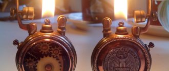
DIY steampunk radio. Let's continue the topic of the second life of outdated gadgets. At one time, FM radios with simple electronic settings consisting of two buttons “Scan” and “Reset” were popular. Such a receiver can become the basis for an interesting design of a loud-speaking receiver, very suitable for use in the workplace, thanks to its compact size and local voice-over of the workplace. The most difficult thing in the work of a radio amateur is not always the manufacture of electronic filling, but the manufacture of a strong and successful case for housing the soldered item. To give the receiver a second life, an attempt was made to make a case in the steampunk style. See what came out of this below.
Antenna connection
Even a properly designed and well-made antenna will perform poorly if there are errors in the connection.
The following conditions must be met:
- Use shielded cable.
- Securely solder contacts and connectors.
- Make sure that the core and screen are tightly connected to the radio input group.
- Ground the antenna.
- If there is interference when powering the radio from the network, when there is no ground wire in the socket, it is better to connect the radio or transistor to ground. For this purpose, most devices have a special socket or terminal.
If the reception quality is not satisfactory, and changing the location and direction of the antenna does not help, you will have to install an amplifier.
A simple and low-cost circuit of such a device is assembled, for example, on an RFMD SPF5043Z microcircuit. The advantage of the design is that the board can be made without chemicals on a 2-sided PCB measuring 15-20 mm and placed in a shielded case.
Causes of signal attenuation
Digital and analog signals gradually attenuate as they move through the transmission medium. The amplitude reduction is indicated in dB - decibels. Attenuation of electromagnetic waves by 2 times corresponds to a loss of 6 dB.
The amount of attenuation depends on:
- the distance traveled by an electromagnetic wave;
- transmitter carrier frequency (the higher, the greater the loss) or wavelength;
- state and material of the conducting medium;
- presence of interference in the path of electromagnetic waves propagation;
- quality of regeneration and correction;
- waveforms.
A digital discrete radio signal, passing through a repeater, is most often completely restored without loss of information.
Analog messages, when amplified, retain all acquired distortion and noise. The signal to noise ratio gradually deteriorates, and at some point the amplification becomes meaningless, since it is impossible to recover the information.
The most common form of interference on transmission lines is crosstalk. The cause of distortion may be equipment malfunctions or insulation cracks. When transmitting signals through wires, pairs are intertwined to eliminate interference.
The shielding properties of wall materials and building decoration can also weaken the radio signal. Strong screen - metal siding, aluminum sandwich panels, corrugated sheet roofs, metal tiles, etc.
(votes: 5 , average rating: 2.00 out of 5)
Radio receiver circuit
I don’t know how to do digital tuning, so it will just be a variable resistor; for this VHF unit, 4.6 volts is enough to completely cover 87-108 MHz. Initially I wanted to insert an ULF on P213 transistors, since I had assembled and rebuilt the “retro” one, but it turned out to be too bulky, so I decided not to show off.
Well, a surge filter is installed, of course it won’t hurt.
There was no suitable dial indicator, or rather there was one, but it was a pity to install it - there were only 2 left, so I decided to remake one of the unnecessary M476s (as in Ocean-209) - I straightened the needle and made a scale.
Backlight - LED strip. The vernier is assembled from parts of various radios, from tube radios to China. The entire scale with the mechanism is removed, its body is glued together from many wooden parts, the rigidity is given by the textolite on which the scale is glued and all this is pulled to the receiver body, simultaneously additionally pressing the front panels (those with a mesh), which are also removed if desired.
Scale under glass. The tuning knobs are from some radio from a junkyard, tinted.
Overall, a flight of fancy. I have long wanted to try out the curvature of my hands by building something similar. And here there was absolutely nothing to do, and scraps of plywood from the renovation remained, and the mesh turned up.
Radio receiver housing, decorative and protective elements
The acoustic characteristics of a radio receiver are determined not only by the frequency characteristics of the low-frequency path and loudspeaker, but also largely depend on the volume and shape of the housing itself. The body of the radio receiver is one of the links in the acoustic path. No matter how good the electroacoustic parameters of the low-frequency amplifier and loudspeaker are, all their advantages will be reduced if the radio receiver housing is poorly designed. It should be borne in mind that the body of the broadcast receiver is at the same time a decorative structural element. For this purpose, the front part of the case is covered with radio fabric or a decorative grille. Finally, to protect the radio listener from accidental damage when touching live parts, the chassis of the radio receiver in the housing is protected by a rear wall on which the power circuit is interlocked. Consequently, decorative and protective structural elements, which are elements of the acoustic path, as well as methods of their mechanical fastening, can have a significant impact on the quality of reproduction of sound programs. Therefore, we will consider each element of the design of the broadcast receiver housing separately.
Radio receiver housing
must satisfy the following basic requirements: its design must not limit the frequency range regulated by GOST 5651-64; the manufacturing and assembly process must meet the requirements of mechanized production; manufacturing costs should be low; External design is highly artistic.
To satisfy the first requirement, the housing must provide good reproduction of the low and high frequencies of the radio audio range. For this purpose, it is necessary to make preliminary calculations of the shape of the hull. The final determination of its dimensions and volume is verified by the results of tests in an acoustic chamber.
In acoustic calculations, a loudspeaker diffuser is considered as a piston oscillating in the air, creating areas of high and low atmospheric pressure during forward and reverse movement. Therefore, it is far from indifferent in which housing the loudspeaker is placed: with an open or closed back wall. In a housing with an open rear wall, the condensation and rarefaction of air arising from the movement of the rear and front surfaces of the diffuser, bending around the walls of the housing, overlap each other. In the case when the phase difference of these oscillations is equal to n, the sound pressure in the plane of the diffuser is reduced to zero.
Increasing the depth of the housing according to design requirements is quite acceptable. The housing dimensions of radio receivers that have several loudspeakers cannot be calculated using the above formulas. In practice, the dimensions of multi-loudspeaker enclosures are determined experimentally based on the results of acoustic tests.
Tabletop broadcast receiver housing designs with a closed back wall are usually not used. This is explained by the fact that it is very difficult and impractical to design radio receiver housings with a closed volume, since the heat exchange mode of radio components deteriorates. On the other hand, enclosures with a tightly sealed back wall cause the speaker's resonant frequency to increase and cause unevenness in the frequency response at higher frequencies. To reduce the unevenness of the frequency response at high frequencies, the inner side of the housing is lined with sound-absorbing material. Naturally, such a complication of design can only be allowed in high-class radios, in furniture with external speaker systems.
To fulfill the second requirement for enclosures, it is necessary to be guided by the following considerations: when choosing a material for the enclosure, it is advisable to take into account the standards recommended by GOST 5651-64 for sound pressure amplification paths, given in Table. 3.
Table 3
| Standards by class | |||||||||
| Options | |||||||||
| Higher | |||||||||
| Frequency characteristics | KV, | 60-6 LLC | 80-4000 | 100-4 LLC | |||||
| Stick of the entire tract | NE, | ||||||||
| Sound Gains | Dv | ||||||||
| Vomu pressure | VHF | 60-15 LLC | 80-12 000 | 200-10000 | |||||
| Options | Range | Standards by class | |||||||
| Frequency characteristics | KV, | 150-3500 | 200-3000 | ||||||
| Stick of the entire tract | NE, | ||||||||
| Sound Gains | Dv | ||||||||
| Vomu pressure | VHF | 150-7000 | 400-6000 | ||||||
As can be seen from table. 3, depending on the class of the radio receiver, the frequency range standards of the entire amplification path for sound pressure also change. Therefore, it is not always advisable to choose high-quality materials with good acoustic properties for all classes of radio receivers. In some cases, this does not lead to an improvement in the acoustic characteristics of the receivers, but increases their cost, since the loudspeaker is selected in accordance with GOST standards, which determines the range of reproduced frequencies. For these reasons, there is no need to improve the acoustic characteristics of the housing when the sound source itself does not provide the possibility of their implementation. On the other hand, the low-frequency path, which has a narrower frequency range, makes it possible to reduce the cost of the design of the low-frequency amplifier.
According to statistics, the cost of a wooden case ranges from 30-50% of the total cost of the main components of the receiver. The relatively high cost of the housing requires the designer to pay careful attention to the choice of its design. What is acceptable when designing high-class radio receivers is completely inapplicable for class IV receivers, designed for a wide range of consumers. For example, in radios of the highest and first classes, in some cases, the case walls, to improve sound reproduction, are made of separate pine boards laid between two thin sheets of plywood. The front sides of the case are covered with valuable wood veneer, varnished and polished. At the same time, cheap plywood, abundant wood veneer, textured paper or plastics are used to make radio cases of classes III and IV. Metal cases are currently not used due to
satisfactory acoustic qualities and the appearance of overtones that are unpleasant to the ear.
To analyze the design, it is advisable to use the so-called unit cost, i.e. the cost per unit volume or weight of the material. In each specific case, knowing the cost of the housing and the amount of material used, it is possible to determine the unit cost. Regardless of the volume of material spent on the manufacture of the body for a certain technological process of its external finishing, the unit cost has a constant specific value. For example, when producing receiver housings at a specialized enterprise or in workshops, the specific cost is 0.11 kopecks. This unit cost value also takes into account overhead costs: the cost of the material, its processing, finishing, wages. It should be borne in mind that the value of the unit cost of the housing corresponds to very specific materials and technological processes. Value 0.11 kopecks. refers to cases made of plywood, covered with cheap veneer (oak, beech, etc.) and varnished without subsequent polishing. For cases carefully polished and covered with more valuable types of wood, the specific cost increases by approximately 60%. Thus, to determine the cost of a wooden radio case, it is necessary to multiply the specific cost by the volume of material used (plywood).
The process of gluing the body of a radio receiver with valuable wood and subsequent polishing is quite labor-intensive, as it contains many manual operations, requires large areas for its processing and tunnel ovens for drying the treated surfaces. In order to save veneer, which is in short supply for a number of enterprises, it is replaced with textured paper, on which a pattern of wood fibers is applied. However, pasting radio receiver cases with textured paper does not improve the situation, since to create a good presentation, multiple varnish coatings (5-6 times) are required, followed by drying in tunnel ovens. In addition, an additional operation is introduced - painting the corners of the body where the sheets of textured paper meet. The cost of buildings finished in this way does not decrease due to the high labor intensity of the work.
The choice of material thickness for the walls of the housing should be made taking into account the technical requirements for the acoustic system of the radio receiver. Unfortunately, in the technical literature there is no detailed information about the choice of material grade and its effect on the acoustic parameters of receivers. Therefore, when designing cases, you can only be guided by the brief information presented in the work. For example, in high-end radio receivers to reproduce low frequencies of 40-50 Hz with a sound pressure of 2.0-2.5 n!m2, the thickness of the walls made of plywood or wood boards must be at least 10-20 mm. For radio receivers of classes I and II, when reproducing low frequencies of 80-100 Hz and a sound pressure of about 0.8-1.5 n/m2, a plywood thickness of 8-10 mm is allowed. Housings for acoustic systems of radio receivers of classes III and IV, having a cutoff frequency of 150-200 Hz and sound pressure of up to 0.6 n/m2, can have a wall thickness of 5-6 mm. Naturally, it is very difficult to make wooden cases with a wall thickness of 5-6 mm, since it is impossible to ensure sufficient structural strength. Housings with thin walls are usually made of plastic, however, even in this case, stiffening ribs must be provided to eliminate vibrations of the housing walls.
For economic reasons, manufacturing plastic radio housings is more profitable than wooden ones. Despite the technological and economic advantages of plastics for the manufacture of housings, their use is limited to broadcast receivers with large dimensions and high acoustic characteristics.
It is well known that wood has good acoustic properties, so radios
the higher classes tend to have wooden bodies. For these reasons, plastic housings are made only for class IV radios and very rarely for class III devices.
The radio receiver housing must have sufficient structural strength and withstand mechanical tests for impact strength, vibration resistance and durability during transportation. The use of methods adopted in the furniture industry, i.e., the implementation of butt connections using tenon joints, is not justified by economic considerations, since the manufacturing process becomes more complicated, and therefore the standard time for processing and assembly operations increases. Typically, angular connections of the walls of broadcast receiver housings are performed using simpler methods that do not cause technological production difficulties. For example, the walls of the body are connected with bars or squares, glued into the corner joints, or with the help of wooden strips, inserted with glue into the slots of the parts to be joined. Wooden walls can be connected with metal angles, brackets, strips, etc. And yet, despite measures taken to simplify the technological processes for manufacturing wooden cases, their cost remains relatively high.
The most labor-intensive technological processes are wood veneering, varnishing and polishing of body surfaces. The process of polishing the assembled body is especially difficult in corner joints, since in these cases manual operations cannot be avoided. It is natural, therefore, that the efforts of designers and technologists should be aimed at creating such a hull design, the manufacture of parts of which and assembly processes could be mechanized as much as possible. The most rational in this regard is the prefabricated design of the body, when individual parts of a simple shape undergo final processing and finishing, and then
mechanically combined into a common structure.
Rice. 37. Design of a prefabricated body.
There are other designs of collapsible housings. One of the domestic radio factories has developed a design in which the side walls are connected by metal panels using bolted connections. In this case, the radio receiver chassis is an independent unit, independent of the housing design.
Naturally, the examples given do not exhaust all the possibilities for developing design designs for split housings. One thing is obvious - such designs are the simplest and cheapest.
Necessary first steps before opening
The first thing to start with is completing the necessary documentation. First of all, you need to open a legal entity, for example, a company, the charter of which will indicate the following types of activities:
- creation of television and radio projects;
- advertising of a commercial and political nature;
- television and radio broadcasting;
- activities related to the media;
- the possibility of purchasing studio space for radio stations and various facilities used for radio broadcasting.
Preparation for activities
In this paragraph we will tell you how to create your own radio. When the necessary documents are completed, it’s time to register the media and begin developing the frequency. To do this, you will need to write an application for its provision. At all these stages, it is advisable to consult with a lawyer in order to make the best decision.
Before attempting to obtain a frequency, it is necessary to prepare information regarding what power the transmitter will be used, where it is intended to be located, and where the radio station itself will be located.
When calculating possible prospects, it is worth taking into account the fact that you cannot buy a radio frequency, since it is a state resource. It is not sold as a product, but is played out in a competition between applicants. In this regard, it may happen that someone else receives the frequency.
If this happens, don't despair. Sometimes the competition is won by the one who currently does not plan to carry out his own broadcasting on the received frequency. In this case, the conversation about renting it will be relevant.
Supply and demand
You need to understand that a radio station is an information product, and you can make money on it only if listeners like it. If this does not happen, then there is no need to talk about any future.
Before you create your own radio, you need to think about what the radio station will be like (style, air content, the notorious highlight). How will it differ from competitors? The more unique elements a new radio station has, the greater its chances of becoming one of the most popular or at least profitable.
It's impossible to please everyone!
Modern radio stations, as a rule, choose a specific format aimed at a specific target audience: young people, those over 40, progressive people a little over thirty, fans of club music, etc. You won’t be able to please everyone, so you need to understand what the the target audience of the new station - for whom the presenters will broadcast on its waves and what genre of music will be a priority.
The moment of demand is quite important, the technical side is related. To understand which direction is best to broadcast, you need to ask yourself what people want but aren’t getting. By answering it, you need to turn the radio station into satisfying the desires of the target group of radio listeners.
Necessary equipment costs
Let's move on to the most important question of how much it costs to create a radio station. One of the main costs will be those associated with obtaining frequencies and registering media.
In order for the station to start broadcasting, it will be necessary to purchase or rent premises in which it will be possible to set up a studio, a place for a DJ and guests (interesting personalities should periodically appear on air).
You also cannot do without an equipment room, where all conditions will be created for the sound engineer to work comfortably. In this case, you will also need a candidate for the position of secretary and manager, whose responsibilities will include some administrative issues and promotion of the station (necessary contacts, negotiations regarding the sale of advertising time, etc.).
As for equipment, for normal operation of the station you need to purchase a computer, the necessary software for quickly working with music, a transmitter, antennas, a good headset and microphones.
On average, it will take about 500 thousand rubles to create your own radio. However, much will depend on the city in which it was decided to start its activities. The larger the settlement, the higher the amount of initial capital will be.
Original do-it-yourself retro amplifier
Original do-it-yourself retro amplifier
Somehow, at one fine moment, I finally got tired of the wheezing, grunting and wild distortion from not serious computer speakers.
Brief description of the amplifier and its characteristics: Amplifier power 2x25W, made on TDA 7265 chips - this is the main amplifier, TDA 1517 is a headphone amplifier 2x5W, these are the main ones.
Its superiorities are of course obvious, at least in terms of output power. But I made it not only for the ears, similar copies that are on sale do not meet my needs at all... and including ease of use. For example, to connect headphones with a thick 6.3 mm Jack plug, this is finally a whole epic with adapters and other nonsense, not to mention the fact that they cannot fully pump up such headphones with decent quality. The appearance of purchased products leaves much to be desired, and you want to put such boxes under the table so that you never see them, where it is inconvenient to turn them on; this amplifier is free of this drawback, because it turns on and off synchronously with the computer. All backlighting is turned off with a button on the back wall so as not to interfere with using the computer in the dark; after the next turn on, it automatically turns on again. Buttons on the front panel “NETWORK” and turning off and turning on the speakers. I wanted to make the indicator similar to the indicators of the famous amplifiers of my youth. Inspired by memories of turbulent times, he began to work. The stylish indicator that I would have liked was not possible to purchase. It was decided to perform it myself, using specially purchased Chinese testers. Milliammeters were removed from them, the red arrows were repainted black. The scale was drawn in the Front Designer program, with subsequent modification in Corel Drav, because the first one sucks at handling different fonts, but it was necessary to write it in a more interesting way. Trying on indicators. Then they are put away until the final assembly of the device (very delicate parts, they can easily be damaged). For control, a voltage amplifier is soldered so that there is no influence on the audio path and the operation is correct. We check - everything is fine, it works perfectly. The diagram was found on the network from some Soviet Soviet mafon, in my opinion I didn’t remember Spring. Here is the scale, the inscription mr. Kolesov is my last name, I won’t die of modesty... and I wanted to make some kind of name... copying some brands is stupid in my opinion. And it’s so unusual, and you can pin your friends... Of course, I wanted to make a classic regulator, a big round one, definitely not a push-button... So that when you touch and rotate, you feel like you’re waving a thing, and not some kind of toy Chinese junk... On the encoder, the adjustment disappeared by itself, I needed a position light on the handle, but it wouldn’t be possible to rotate it endlessly with a wire. In general, I didn’t bother and decided to do it with a variable resistor. In the end, if it starts to creak, change it within 5 seconds. And so for your attention - another perversion... After searching around the house I came across a tube of cream. After negotiations with my wife, she presented me with a lid from him for later tearing apart. As planned, there was a backlight on the handle so that the position of the regulator could be easily and quickly determined (this is especially true in the dark). A 1mm hole was drilled, and I will attach a light to the back later. We put an LED on the epoxy, having previously covered it with foil (it is very bright, I didn’t want it to shine through the walls of the handle), at the same time the excess resin leaked into the hole formed a kind of light guide, the smudges are sanded off and the surface is completely smooth, it’s very difficult to guess where the hole is until you light it little light The scale was made in the Front Designer program and the inscription and symbols were made in Corel Drav. In a designer, you won’t have enough options. The scale printed on glossy paper is placed between 2 sheets of organic matter, everything is connected for subsequent stages of work. It didn't turn out bad. In principle, everything worked out as I wanted. It was decided to make the supports for this product in the classic design style of radio equipment - chrome-plated, but with a slight twist ala UFO. Blue lighting was planned at the base of the legs. It was made from what was also found on the balcony in a pile of rubbish. Chromed furniture pipe 25mm, organic 3mm (adjusted by corefan), of course I went and bought some lights + glue (superglue and epoxy resin). The blanks are cut, glued and lights are glued into them, incorrectly for transmitting the light flux, but more on that later... A round-shaped layer of organics is provided so that later when pouring the epoxy does not leak out... The blank from the pipe is tightly placed on the base. The parts are dry. Processing has been carried out. Excess plexiglass has been removed, the edges have been carefully polished so as not to spoil the chrome on the metal part of the leg. The trial switching on of the lights was not impressive and it was decided to make a diverging lens... The light hits it and is scattered in different directions. This combined photo shows the dispersion effect made by simply manipulating the drill... At the final stage, rubber gaskets were made from a bicycle inner tube... aluminum foil was glued to the gasket on the inside, (to reflect light) everything was glued together for a transparent moment. There are a minimum of switches and connectors, only the essentials. Why does a power amplifier need extra bells and whistles? All settings are in the computer's sound card. Switch "Network". The speaker switch, the signal to the headphones is constant, regardless of whether the speakers are turned on or not - this is also part of the intended plan. Nowadays you won’t find an amplifier with such a circuit, even serious receivers are made according to the principle “plug in headphones and there is no signal to the speakers,” but previously all amplifiers were made exactly according to this circuit, as I did. I don’t know if it’s convenient for someone and vice versa, but for me this signal distribution scheme is very relevant. The holes for the switches were selected using wood bits. Also, a crown of a larger diameter was used for the skirt around the hole in order to highlight the switches with backlighting (the scratched and untreated surface of the organic material catches the light). Headphone jacks are also installed. And be sure to have different diameters Jack 3.5 mm and Jack 6.3 mm so that later you don’t have to worry about all sorts of adapters. What kind of plug do the headphones have with this one and you can easily plug it in without any problems. Painting first with silver to distribute the light evenly and then with paint so as not to highlight everything around the panel. 4 lights and here is the final result, there is also an LED inside the headphone jacks for the overall picture. In fact, all electronic small items were found at home; only amplifier chips and switches with headphone jacks were specially purchased. I made and developed the boards myself, except for the one for the indicator, I found this one on the Internet. Since I already have some experience in building electronic devices, this was not particularly difficult for me. Even I would say it was interesting to remember my youth. The amplifier is installed, the TDA 7265 microcircuit is assembled, but the dashita with minor modifications for its needs beats honest 2x25W not HI - END of course, but for the computer to keep the ears happy, it’s quite enough, in the end, if you want something more serious, then the computer has a digital output, and it can be connected to the receiver. The relay switches the speakers (the button on the panel only turns on the relay). This is not unreasonably due to the fact that the contact of the relay is more reliable than that of the switch. I know this from my own experience... For headphones, a separate small amplifier was made 2x5W, a little too big in power, of course, but it will pump up any headphones 100%, listening to powerful large headphones left a positive impression, the microcircuit heats up quite strongly at high volumes, so then during final assembly I’m thinking of sticking on a small radiator for good measure . I made a separate amplifier because I did not want limiters such as resistors, etc., to be present in the audio path. which would have to be installed if we took the signal from the main amplifier. And here the signal, immediately after amplification, goes to the sound emitters without limitation, which certainly has a positive effect on the quality. A set of parts for the power supply. A case from some kind of printer was found for the “useful things” at home, the transformer was fitted by Corefan (by the way, a special thank you to him for such an element... despite its small size, the trans showed unexpected results when dialing: at 25V it stably delivered 10A without heating!! !) The photo also highlights the starter relay from the car. Also found at home, they are supposed to turn on the amplifier using a computer. We take 12V from the computer and voila.. This is so as not to worry about turning the amplifier on and off every time, it will be controlled from the computer and work synchronously with it. For normal work without a computer, I will put a switch on the back wall that short-circuits the relay contacts and excludes it from the circuit. I had to tinker with the body, but since this is the face of the product, it was worth it. The chipboard was found again in a pile of rubbish on the balcony, left over from some old furniture and left as something useful and could come in handy... which is exactly what happened. Having cut the parts to size, I screwed everything together with self-tapping screws. Before assembly, I coated the joints with glue for reliability. I cut holes for installing control and display elements. Raw edges don't look very good. The ends were processed using a manual milling cutter. I had to process it in several passes to get perfect uniformity of all edges. To secure the rear wall, bars were installed; a large indentation from the edge was made in order to hide the cooling radiator and all wire switching elements, etc. Due to this, the amplifier can be placed close to the wall. The stages of puttying and painting have been completed, puttying was done with polymer putty with the addition of PVA glue for good retention on the surface, primer after each layer, of course. Painting with NC paint and then varnishing with NC varnish. Subsequent polishing of the coating with polishing paste and finishing polish for the car body. As a result, you get a beautiful polished surface, which turns out cooler than on a grand piano.
Necessary advertising costs
This item will also require expenses. It’s worth taking a step back and saying that with the help of your radio you can make money by placing someone else’s advertisements. If you look, for example, how much radio advertising costs in Moscow, you will see impressive prices, which you, as the future owner, cannot but please. Let's go back.
So, by the time the broadcast starts, you need to prepare the necessary commercials for the new radio, a stylish screensaver that would make the radio station recognizable. It will also be necessary to place advertisements in popular publications and on local television.
You can also make your name known through advertising on Yandex, Google, as well as on social networks. The latter, by the way, should not be neglected. The fact is that tens of thousands of residents of the city where the new radio will open visit social networks. The good news is that the administration of the same VKontakte website provides the opportunity for advertising, which, moreover, will be displayed exclusively on the pages of representatives of a specific target audience (residents of a certain city who are of the current age for the radio station).
Since it is unlikely that you will be able to fill the airwaves on your own every day for 24 hours right away, there will be a need to conclude an agreement that allows you to broadcast broadcasts from a regional radio station. A little advice: all costs need to be calculated before creating your radio.
How to make a steampunk hull
Please do not judge strictly - this is the first attempt. In addition to developing a stylish housing for the radio, the goal was to minimize costs and use available components and materials. Moreover, the materials are easy to process.
Before starting work, let's study the receiver's controls, which will need to be placed on the body. As mentioned above, these are two tuning buttons “Scan” - tunes the station after each press from the last radio station to the next radio station higher in the range. When tuning to the latest radio station, returning to the beginning of the range is done by pressing the “Reset” button. In the original receiver, the third button turns on the flashlight (it was not an LED, but a light bulb!) and is not used in this design. The volume of receiving stations is regulated by a potentiometer combined with the power switch. The sound signal is sent to the headphones; of course, there is no speech in any stereo signal in such a receiver. The headphone cord is also an antenna for the radio. Controls can be purchased at a store or used from old equipment. Controls were purchased for this design; the total price of two buttons, a switch, an antenna terminal and a potentiometer (30 kOhm) with a knob did not exceed 150 rubles (2013). A sensitive loudspeaker extracted from a small-sized speaker was used as a loudspeaker. Head resistance 8 ohms.
Column - donor Loudspeaker
1. The body is based on a piece of white polystyrene sheet measuring 200x130 mm and 1.5 mm thick. The sheet contains markings for controls and body bends to form side walls with a height of 40 mm. It is possible to use plastic junction boxes purchased at an electrical goods store as a housing.
2. On the inside, following the marking of the bend of the walls, small cuts are made, for example, with the sharp end of scissors or a knife, 1/4 - 1/3 of the thickness of the plastic.
3. Use a gas lighter evenly
We heat the entire bend until the plastic softens and form the side wall.
The flame should not reach the bend point 10-15 mm. This will result in the most intense heating. We perform the same operation with the second wall. The resulting “U”-shaped body should rest with all ends of the side walls on the surface. Body parts Marking the workpiece
4. After making the body, you can make holes. The sound from the speaker will be transmitted towards the listener through the bell. A siphon was used as a socket to remove water from the floor (made in Spain :)). The hole for the speaker - the bell can be drilled with a thin drill and then trimmed with a knife.
5. The front and back walls are cut out with your own hands using tailor’s scissors, also from sheet polystyrene and glued with glue for gluing plastic models.
6. We process the gluing seams with fine sandpaper to smooth out the edges.
7. The drain is made of an unknown plastic and it was not possible to glue it. To maintain the style, the included threaded clamp was used, which was attached to the body with hot-melt adhesive from the inside. At the same time, we secure the loudspeaker with hot glue.
Holes in the housing Clamp secured Receiver housing
8. We install control elements into the resulting housing. We use the battery compartment from the old receiver, from which we remove unnecessary plastic.
9. Using a soldering iron, carefully remove the potentiometer from the receiver board and solder the extension conductors for:
— setting buttons;
- loudspeaker;
— volume control potentiometer;
— power switch;
— power supply for the receiver, minus to the switch, plus to the battery compartment;
— antennas, it is better to wrap the antenna wire around a pencil and place it, slightly stretched, in the receiver body, so you may not need to connect an external antenna.
10. Solder the conductors to the controls. We insert the batteries. We check the operation of the receiver; if there is no mistake anywhere, the electronics will work immediately.
11. Secure the board, battery compartment and antenna inside the case with hot glue. Look at the photo. Cut out the bottom cover from corrugated cardboard. The retro radio is ready.
Board connected Receiver basement
Within the city limits, the radio receiver receives almost all stations; in the suburbs, the number of received stations may decrease and you will need to connect an external antenna; a piece of wire up to a meter long should be enough. Do not expect high volume from the receiver; if you need to increase the volume, you need to build in an amplifier. An example of an amplifier is given
Once upon a time, we assembled our first simple radios at school age from kits. Today, due to the development of modular design, it is not difficult to assemble a digital radio receiver even for people who are extremely far from amateur radio. This receiver's design is based on the impressive 1935 AWA radio that the author came across in the book Deco Radio: The Most Beautiful Radios Ever Made. The author was so impressed by its design that he wanted to have his own analogue.
The design uses a Nokia 5110 LCD display to display the frequency and an encoder to select it. The volume is controlled by a variable resistor built into the amplifier. To emphasize the design, the author also used an Art Deco style font to display information on the display. The Arduino code contains a function for remembering the last station listened to (which was listened to for more than five minutes).
Step 1: Components
- Arduino Pro Mini
- FTDI programmer
- TEA5767 FM radio module
- Speaker 3W
- PAM8403 amplifier module
- Encoder
- Nokia 5110 LCD display
- Battery charge and protection board
- 18650 battery
- Holder 18650
- Switch
- Breadboard 5x7 cm
- Connecting wires
- Speaker fabric
First of all, if you do not have much experience working with Arduino, you should first build the circuit using a non-printed breadboard. In this case, for convenience, you can use Arduino Nano or UNO. Personally, I use Arduino UNO at the stage of debugging circuits, since it is convenient to use it together with a breadboard to connect the necessary components, practically without using soldering. When you turn on the device, the logo should be displayed on the screen for a few seconds, after which the frequency of the last listened station is loaded from the EEPROM memory. By turning the encoder knob you can adjust the frequency by changing stations.
When everything works well on the breadboard, you can move on to the main assembly, using the more compact and cheaper Arduino PRO Mini, which, moreover, has lower consumption. But before that, let's see how everything will be located in the case.
Step 3: Design the Case
The 3D model was developed in the free but quite powerful Fusion 360 program.
Step 4: 3D Printing and Processing
FormFutura “wooden” plastic was used for printing. This is a rather unusual plastic, the peculiarity of which is that after printing the parts have a look similar to wood. However, when printing with this plastic, the author encountered a number of problems. Small parts printed without problems, but the body, the largest part, did not print the first time. When trying to print it, the nozzle constantly became clogged, the situation was aggravated by regular power failures, which is why the author even had to purchase a UPS for the printer. Ultimately, the body was printed on top of the unprinted blank. This solution, however, is not really a solution to the problem, just a one-time way out of the situation, so the question remains open. Since the print did not work out successfully, the author then decided to sand the body, putty it with wood putty and varnish it. Yes, this plastic doesn’t just look like wood, it’s essentially fine wood dust mixed with a binder plasticizer, so the parts printed with it are practically wooden and can be processed using ordinary wood.
Step 5: Putting it all together
The next step is to install the electronics into the housing. Since everything has already been modeled in Fusion 360, this won't be a problem. As you can see, each component has its own position in the case. The first step was to unsolder the Arduino Pro Mini, after which the code was loaded into it. The next step is the power source. The project used a very convenient and compact Wemos board, which is simultaneously responsible for charging the battery, protecting it, and also increases the voltage for consumers to the required 5 volts. Instead, you can use a conventional charge and protection module, and increase the voltage with a separate DC/DC converter (for example TP4056 + MT3608).
Next, the remaining components, speaker, display, and amplifier are soldered. Also, even though there are power supply capacitors on the amplifier module, it is advisable to add another one (the author set it to 330 uF, but 1000 is also possible). The sound quality (if 10% THD can be called quality) of the sound of the PAM8403 amplifier very much depends on the power supply, as does the operation of the radio module. Once everything is soldered and tested, final assembly can begin. First of all, the author glued the grille and radio fabric on top of it.
Push. Radio fabric is a specific thing, and every stall does not sell it. However, in every women's needlework store you can buy such a thing as canvas (fabric for cross stitch). It is inexpensive and very suitable as a replacement for radio fabric; it comes in different colors. Take natural (not synthetic) and with the largest cell. By the way, it fits perfectly with the design of this radio.
All other boards are secured in place using hot-melt adhesive. You can use hot glue a lot, but it works really well for these purposes, considering that most modules do not have mounting holes. Although I prefer to use double-sided "car" tape for these purposes.
Step 6: Firmware
This step should have been placed higher, since it needs to be flashed at the debugging stage. The basic idea of the code is this: when the encoder knob is turned, the frequency is searched, when the encoder knob remains in the same position for more than 1 second - this frequency is set for the FM receiver module.
If(currentMillis - previousMillis > interval) { if(frequency!=previous_frequency) { previous_frequency = frequency; radio.selectFrequency(frequency); seconds = 0; }else
The FM radio module takes about 1 second to tune to a new frequency, so it will not be possible to change the frequency in real time by turning the encoder knob, because in this case, the tuning of the receiver will be very slow.
I tried to make this homemade VHF receiver in a “retro” style. Front End from car radio. KSE marking. Next, the IF unit on the KIA 6040, the ULF on the tda2006, the 3GD-40 speaker, in front of which there is a 4-5 kHz notch, I don’t know exactly, I selected it by ear.
Internet access
It is unnecessary to say that the Internet is an integral part of the life of modern society. Therefore, not using the worldwide network to promote your own radio station would be a global mistake. Quite a lot of young people and freelancers, who, while working at home on a computer, would not mind listening to good music, have long forgotten about a regular radio. Such homebodies (and there are many of them) listen to the radio via the Internet.
Therefore, in order to quickly attract the largest number of regular listeners, you need to bring the radio station to the Internet. To do this, you can use Winamp, some Internet services and a server, with the help of which users can listen to the radio station. There are many step-by-step instructions on the Internet that describe in detail what and where to click.
It is advisable that the radio station have its own website with the ability to download a plugin that allows you to listen to the radio without logging into an Internet browser. Competition in this type of activity is at a fairly high level, so you will have to make every effort and create a high-quality product that will be worthy of the sympathy of thousands of listeners. In the future, when your radio station develops, you can consider how to organize radio broadcasting as a franchise .
Chassis manufacturing
The photographs show the third chassis option. The plate for fastening the scale is modified to be placed in the internal volume of the box. After completion, the necessary holes for the controls are marked and made on the board. The chassis is assembled using four wooden blocks with a cross-section of 25 mm by 10 mm. The bars secure the back wall of the box and the scale mounting panel. Posting nails and glue are used for fastening. A horizontal chassis panel with pre-made cutouts for placing a variable capacitor, volume control and holes for installing an output transformer is glued to the lower bars and walls of the chassis.