A drone is a very expensive gadget. How to assemble a quadcopter yourself at home? In this tutorial, I'm going to tell you how to make your own quadcopter on the cheap. The copter frame and flight controller are homemade. The assembly design is accessible even for beginners.
The frame consists of an aluminum antenna (rod), an aluminum fan blade and wood. Arduino UNO along with MPU6050 (Gyroscope + Accle) is used as the flight controller.
Introduction
Now that you have selected or designed the UAV frame, motors, rotors, ESC and battery, you can begin selecting a flight controller. The flight controller for a multi-rotor unmanned aerial vehicle is an integrated circuit typically consisting of a microprocessor, sensors, and input/output pins. Once unboxed, the flight controller does not know what specific type or configuration of UAV you are using, so you will initially need to set certain parameters in the software, after which the specified configuration is loaded on board. Rather than simply comparing currently available flight controllers, the approach we've taken here lists which parts of the PC are responsible for which functions, as well as the aspects to pay attention to.
Necessary components, parts and equipment
For the Arduino-controlled quadcopter project we will need:
- - wires;
- — 3.7 V lithium batteries;
- — transistor: ULN2003A Darlington Transistor (you can take a transistor that supports larger loads);
- — motors: 0820 Coreless Motors;
- — microcontroller: Arduino Uno;
- - accelerometer/gyroscope: MPU-6050 board (cheap and cheerful all-in-one option);
- — 3D printer or access to it for printing parts of the quadcopter design;
- — tools (including a soldering iron and the ability to use it!).
Links to order the necessary electronic equipment used in the project from China
- BUY 3.7 V lithium batteries (Be careful, among the products offered you need to find exactly the one that suits you!);
- BUY transistors ULN2003A;
- BUY engines;
- BUY Arduino Uno R3;
- BUY MPU-6050;
Main processor
8051 vs AVR vs PIC vs ARM: A family of microcontrollers that form the basis of most modern flight controllers. Arduino is based on AVR (ATmel) and the community seems to be focused on MultiWii as the code of choice. Microchip is the main manufacturer of PIC chips. It's hard to argue that one is better than the other, it all comes down to what the software can do. ARM (e.g. STM32) uses a 16/32-bit architecture, with dozens using 8/16-bit AVRs and PICs. As single board computers become less and less expensive, a new generation of flight controllers are expected to emerge that can run full operating systems such as Linux or Android.
CPU: They are usually a multiple of 8 (8-bit, 16-bit, 32-bit, 64-bit), which in turn indicates the size of the primary registers in the CPU. Microprocessors can only process a set (maximum) number of bits in memory at a time (cycle). The more bits a microprocessor can process, the more accurate (and faster) the processing will be. For example, processing a 16-bit variable on an 8-bit processor is much slower than on a 32-bit one. Note that the code must also work with the correct number of bits, and at the time of this writing, few programs use code optimized for 32 bits.
Operating frequency: The frequency at which the main processor operates. It is also called “clock speed” by default. Frequency is measured in hertz (cycles per second). The higher the operating frequency, the faster the processor can process data.
Program Memory/Flash: Flash memory is where the main code is stored. If the program is complex, it may take up a lot of space. Obviously, the larger the memory, the more information it can store. The memory is also useful when storing in-flight data such as GPS coordinates, flight plans, automatic camera movement, etc. Code loaded onto flash memory remains on the chip even after power is turned off.
SRAM: SRAM stands for Static Random Access Memory and is the space on the chip that is used when performing calculations. Data stored in RAM is lost when the power is turned off. The higher the amount of RAM, the more information will be “readily available” for calculations at any given time.
EEPROM: Electrically Erasable Programmable Read Only Memory (EEPROM) is typically used to store information that does not change during flight, such as settings, as opposed to data stored on SRAM, which may include sensor readings, etc.
Additional I/O Ports: Most microcontrollers have a large number of digital and analog input and output ports, on a flight controller some are used for sensors, others for communications, or for general input and output. RC servos, gimbal systems, buzzers and more can be connected to these additional ports.
A/D converter: If the sensors use on-board analog voltage (usually 0-3.3V or 0-5V), an A/D converter must convert these readings into digital data. As with the processor, the number of bits that can be processed by the ADC determines the maximum accuracy. Related to this is the clock rate at which the microprocessor can read data (number of times per second) to ensure that information is not lost. However, it is difficult not to lose some data during this conversion, so the higher the ADC resolution, the more accurate the readings will be, but it is important that the processor can handle the speed at which the data is being sent.
New drone from DJI, Intel and Ryze Tech
From January 9 to 12, the international consumer electronics exhibition CES 2022 was held in Las Vegas. The world-famous company DJI Innovations, together with Ryze Technology, as well as with the participation of Intel, presented a very interesting and unusual new product - the Tello quadcopter. Tello is a mini drone and is positioned as a toy or entertainment drone, equipped with a 720p camera, and its price is just over 100 euros.
General characteristics
The new Tello quadcopter is a mini-drone with extremely modest dimensions but varied functionality. Manufacturers created this model specifically for children and teenagers, but it will also be interesting for adults. Tello's flight duration is up to 13 minutes on a single charge, and the flight range is about 100 meters. Broadcasting in 720p resolution is carried out on the smartphone screen through a special Tello application. Photo and video settings are also available in it. The quadcopter comes with a battery, a set of spare blades, and a blade protection kit.
Ryze Technology: a new player in the market
Tello is a joint product of DJI and Intel with a young startup Ryze Technology from the same China. The company was founded in 2022. For now, the company is focused on producing drones equipped with a camera, as well as an arsenal of all kinds of “smart” functions and training capabilities. The company aims to increase the interest of young people in modern technology.
In the development of the Tello drone, the young startup received help from eminent “giants”: a flight controller was taken from DJI, and a powerful processor was installed from Intel. All this power fits into a small package that you can take with you anywhere. Tello can “learn”: the owner will have the opportunity to program the drone, and according to the developers, it will be so easy that not only teenagers, but even children can handle programming!
This is not to say that Tello is a product from DJI, although the drone is visually similar to Spark. Still, DJI and Intel are rather partners who participated in the development of the quadcopter. In addition, DJI will be offering Tello for purchase in their online store.
Features of the new model
The Tello quadcopter falls into the category of fun drones (fandrons) rather than camera drones. This little guy can do fun tricks and somersaults in the air that will be a lot of fun for younger pilots. Tello can be safely launched from the palm of your hand and placed on it automatically. Moreover, the launch can be done by lightly throwing the quadcopter into the air.
Tello has a number of pre-installed functions for photo and video shooting (for example, Circle Mode, 360 Grad, Up-and-Away). Image stabilization is done digitally, not mechanically. The built-in 14-core processor from Intel is responsible for this. The quadcopter takes 5 megapixel photos. In addition, Tello is compatible with VR glasses. And at the same time its weight is only 80 grams!
Among other things, the new product has a number of useful functions for flight safety. With just a swipe of your finger on the app, the drone can automatically take off or land. Using visual and audio signals, Tello warns you when your battery is about to run low. If the signal is lost, the Failsafe function is activated - the drone will automatically land. The new product also has a built-in visual positioning system.
Programmable toy
Ryze Technology paid special attention to the educational and training aspect in its new product. With Tello, children and teenagers can easily and playfully learn the basics of programming (in the children's programming language Scratch).
Scratch is a programming language created in 2007 specifically for children of primary and secondary school age. With its help, children can easily learn about the basics of programming, as well as show their creativity and develop communication skills. Scratch is an entire online community of interested children, teenagers and teachers who support each other.
It is thanks to Scratch that children will have the opportunity to expand the flight functions of Tello. For example, flips and somersaults in the air can be programmed in 8 different directions. Other intellectual functions, studied and tested in a playful way, will also become possible.
Nutrition
Often, a flight controller specification will describe two voltage ranges, the first being the input voltage range of the flight controller itself (most operate at a nominal voltage of 5V), and the second being the input voltage range of the main microprocessor (3.3V or 5V). Since the flight controller is an embedded device, you only need to pay attention to the input voltage range of the controller. Most multi-rotor UAV flight controllers operate at 5V, as this is the voltage produced by the BEC (see the Powerplant section for more information).
Let's repeat. Ideally, you do not need to power the flight controller separately from the main battery. The only exception is if you need a backup battery in case the main battery is producing so much power that the BEC cannot produce enough current/voltage, causing a power outage/reset. But, in this case, capacitors are often used instead of a backup battery.
Further modernization of the quadcopter using Arduino
The main problems with a small quadcopter are its cost and weight. You can look for larger and more powerful motors, but this will not particularly improve its performance. What will really help you (if you are willing to shell out more money) are brushless (valve) motors. In terms of characteristics, they are an order of magnitude better, but in addition to them you need to use speed controllers, which will make the quadcopter more expensive.
To reduce the weight of the design, it is best to use Arduino Uno, since for this controller model you can remove the “stitched” microprocessor chip and install it directly on your ProtoBoard. As a result, you will gain about 30 grams of weight, which is quite a lot on such a scale. Additionally, you will need to use several more capacitors, etc. Or, as an alternative, you can use Arduino Pro Mini.
The Arduino program, which was written and presented in the previous section, can be easily expanded and enriched with additional functionality. The most important thing is that at this stage the quadcopter can already automatically stabilize the flight. If you want to set up remote control, you can look towards transmitters/receivers or bluetooth modules. In general, you now have the basis, and there is even more room for further modernization.
Leave your comments, questions and share your personal experiences below. New ideas and projects are often born in discussions!
Sensors
From a hardware point of view, the flight controller is essentially a regular programmable microcontroller, only with special sensors on board. At a minimum, the flight controller will include a 3-axis gyroscope, but no auto-leveling. Not all flight controllers come with the following sensors, but they may also include a combination of them:
- Accelerometer: As the name suggests, accelerometers measure linear acceleration along three axes (let's call them: X, Y and Z). Usually measured in “G (in Russian Zhe)”. The standard (normal) value is g = 9.80665 m/s². To determine the position, the accelerometer output can be integrated twice, although due to output losses the object may drift. The most significant characteristic of three-axis accelerometers is that they sense gravity, and as such, can know which direction is "going down". This plays a major role in ensuring the stability of a multi-rotor UAV. The accelerometer must be installed on the flight controller so that the linear axes coincide with the main axes of the drone.
- Gyroscope: The gyroscope measures the rate of change of angles along three angular axes (let's call them: alpha, beta and gamma). Usually measured in degrees per second. Note that the gyroscope does not measure absolute angles directly, but you can iterate to get an angle that, like the accelerometer, contributes to drift. The output of a real gyro tends to be analog or I2C, but in most cases you don't need to worry about this since all incoming data is processed by the flight controller code. The gyroscope must be installed so that its rotation axes coincide with the axes of the UAV.
- Inertial Measurement Unit (IMU): An IMU is essentially a small board that contains both an accelerometer and a gyroscope (usually multi-axis). Most include a three-axis accelerometer and three-axis gyroscope, while others may include additional sensors, such as a three-axis magnetometer, providing a total of 9 measurement axes.
- Compass/Magnetometer: An electronic magnetic compass capable of detecting the Earth's magnetic field and using this data to determine the direction of the drone's compass (relative to the magnetic north pole). This sensor is almost always present if the system has a GPS input and one to three axes are available.
- Pressure/Barometer: Since atmospheric pressure changes with distance from sea level, a pressure sensor can be used to get a fairly accurate reading of the UAV's altitude. To calculate the most accurate altitude, most flight controllers receive data simultaneously from a pressure sensor and a satellite navigation system (GPS). When assembling, please note that it is preferable that the hole in the barometer body be covered with a piece of foam rubber, this will reduce the negative effect of wind on the chip.
- GPS: The Global Positioning System (GPS) uses signals sent by multiple satellites orbiting the Earth to determine one's specific geographic location. The flight controller can have either a built-in GPS module or one connected via cable. The GPS antenna should not be confused with the GPS module itself, which can look either like a small black box or like a regular “Duck” antenna. To obtain accurate location data, the GPS module must receive data from several satellites, and the more, the better.
- Distance: Distance sensors are increasingly used on drones because GPS coordinates and pressure sensors cannot tell you how far you are from the ground (a hill, mountain or building) or whether you will collide with an object or not. A downward-facing proximity sensor may be based on ultrasonic, laser, or lidar technology (IR sensors may have trouble functioning in sunlight). Distance sensors are rarely included in a standard flight controller package.
A little theory
Regardless of the shape and technical capabilities of the quadcopter, it must have four propellers that rotate in pairs in different directions. This is necessary to ensure stability in the air, since if all the propellers rotate in the same direction, the drone will spin around its vertical axis.
Moving the drone on Arduino and any other controller is done by changing three parameters:
- pitch;
- bank;
- yaw.
The first parameter determines the angle at which the front of the quadcopter is tilted up or down, allowing the drone to descend or ascend. Roll determines the angle of inclination when the right side is lower or higher than the left. Yaw determines the angle of rotation of the Arduino quadcopter around a vertical axis passing through its center of gravity, providing the drone with a horizontal rotation at the desired angle.
Arduino is a small board (comparable to a matchbox) that has its own microprocessor and memory. It has a large number of contacts for connecting components, and the ability to download a program allows you to control them according to a given specific algorithm.
As a result, the Arduino board provides ample opportunities for creating various gadgets, of which the drone is just one example.
At the same time, the Arduino board is very easy to learn, so even people with very vague knowledge of circuit design and programming can work with it. The presence of a large number of textbooks, publications, and video tutorials will allow you to master the simplest operations with the board in just a couple of hours. Direct programming on Arduino is done using the C++ language, which is widely used. At the same time, a large number of standard programs will allow you to quickly master it to a level that is sufficient to control the drone. At the same time, a wide selection of libraries will reduce the time it takes to launch the first drone, preventing the occurrence of childhood errors.
Arduino will not require a soldering iron during assembly, since it is quite possible to get by with a breadboard and a set of jumpers, which at the same time simplifies the work and allows you to quickly correct any shortcomings and errors during assembly.
Flight modes
Below is a list of the most popular flight modes, however, not all of them may be available in flight controllers. “Flight mode” is the way the flight controller uses sensors and incoming radio commands to stabilize and fly the UAV. If the control equipment used has five or more channels, the user can configure the software, which will allow him to change modes through channel 5 (with an auxiliary switch) directly during the flight.
- ACRO is usually the default mode, of all available sensors, only the gyroscope is used by the flight controller (the drone cannot automatically level). Relevant for sports (acrobatic) flight.
- ANGLE - stable mode; Of all the available sensors, the flight controller uses the gyroscope and accelerometer. Angles are limited. Will keep the drone in a horizontal position (but without holding position).
- HORIZON - combines the stability of ANGLE mode, where the sticks are close to the center and move slowly, with the acrobatics of ACRO mode, where the sticks are in extreme positions and move quickly. The flight controller uses only the gyroscope.
- BARO (Altitude Hold) - stable mode; Of all the available sensors, the flight controller uses the gyroscope, accelerometer and barometer. Angles are limited. The barometer is used to maintain a certain (fixed) altitude when no commands are issued from the control equipment.
- MAG (Heading Hold) - heading (compass direction) blocking mode, the drone will maintain Yaw orientation. Of all the available sensors, the flight controller uses the gyroscope, accelerometer and compass.
- HEADFREE (CareFree, Headless, Headless) - eliminates orientation tracking (Yaw) of the drone and thereby allows you to move in a 2D direction according to the movement of the ROLL/PITCH control stick. Of all the available sensors, the flight controller uses the gyroscope, accelerometer and compass.
- GPS/Return to Home - Automatically uses a compass and GPS to return to your takeoff location. Of all the available sensors, the flight controller uses a gyroscope, accelerometer, compass, and GPS module.
- GPS/Waypoint - allows the drone to autonomously follow pre-set GPS points. Of all the available sensors, the flight controller uses a gyroscope, accelerometer, compass, and GPS module.
- GPS/Position Hold - holds the current position using GPS and barometer (if available). Of all the available sensors, the flight controller uses a gyroscope, accelerometer, compass, and GPS module.
- Failsafe (emergency/fail-safe mode) - if no other flight modes have been specified, the drone goes into Acro mode. Of all the available sensors, only the gyroscope is used by the flight controller. Relevant in case of failures in the drone software, it allows you to restore control over the UAV using previously preset commands.
Program for Arduino
The program, which is posted here, stabilizes the quadcopter and allows it to hover in a stable state. The program is the basis for further control and movement of the quadcopter. In addition to the main program, you will need to download the Arduino PID library from this link.
You can read about PID control on Wiki if you are not familiar with these controllers. The PID class for Arduino uses three inputs: setpoint, measurement and output. The output depends on the current position and measurements. The PID controller tries to change the output so that the measurements correspond to the target position. The algorithm uses interesting mathematics. The PID control algorithm tries to work in such a way that the values remain as stable as possible.
Our algorithm uses two PID controllers for stabilization: one for pitch and one for roll. The difference in the rotation speed of propellers 1 and 2 will be the same as the difference in the speed of propellers 3 and 4. Likewise for pairs 1,3 and 2,4. After this, the PID controller changes the difference in speed, bringing the pitch and roll to zero.
Don't forget to check which digital pins from the Arduino go to the motors and change the sketch accordingly.
Software
PID controller (purpose and settings)
Proportional Integral Derivate (PID) is a piece of flight controller software that reads data from sensors and calculates how fast the motors must spin to maintain the desired speed of the UAV.
Developers of ready-to-fly UAVs typically tune the PID controller parameters optimally, so most RTF UAVs fly perfectly straight out of the box. The same cannot be said about custom UAV assemblies, where it is important to use a universal flight controller suitable for any multi-rotor assembly, with the ability to adjust PID values until they meet the required flight characteristics of the end user.
GUI
Graphical User Interface (GUI) is what is used to visually edit the code (using a computer) that will be loaded into the flight controller. The software that comes with flight controllers continues to get better and better; early flight controllers used mostly text-based interfaces that required users to understand almost all of the code and change certain sections to suit the design. Recently, interactive graphical interfaces have been used in GUIs to make it easier for the user to configure the necessary parameters.
Additional features
The software used on some flight controllers may have additional features that are not available on others. The choice of a specific flight controller may ultimately depend on what additional features/functionality are offered by the developer. The list of such functions may include:
- Autonomous Waypoint Navigation - Allows the user to set GPS waypoints that the drone will follow autonomously.
- Oribiting - moving a drone around a given GPS coordinate, where the front of the drone is always directed towards a given coordinate (relevant for shooting).
- Follow me - many UAVs have a “Follow Me” function, which can be based on satellite positioning (for example, tracking the GPS coordinates of a smartphone or a GPS module built into the control equipment).
- 3D Imaging - Most 3D imaging is done after flight using images and GPS data acquired during the flight.
- Open source - the software of some flight controllers cannot be changed/customized. Open source products typically allow advanced users to modify the code to suit their specific needs.
3-D printing of quadcopter parts
One of the first steps is to create the frame of our quadcopter. It was decided to take the path of least resistance and print the frame on a 3D printer. In addition to ease of manufacture, the frame printed on a 3D printer is quite lightweight thanks to honeycomb printing. The parts were designed in Solidworks. Below are all the solid models. You can easily download them and send them to print. Details are saved in .stl format. If you want, you can safely modify and change them using the same Solidworks. The models are parametric, so if you decide to use other motors, you just need to change a few parameters in the model and you will get a ready-made frame for your quadcopter dimensions.
diy_bottom_plate.stl
diy_motormount.stl
diy_quad_boom.stl
As a result you will get something like this:
Additional Considerations
Functionality: Flight controller manufacturers usually try to provide as many features as possible - either included by default or purchased separately as options/add-ons. Below are just a few of the many additional features you may want to look at when comparing flight controllers.
Damping: Even small vibrations in the frame, usually caused by unbalanced rotors and/or motors, can be detected by the built-in accelerometer, which in turn will send appropriate signals to the main processor, which will take corrective action. These minor adjustments are not necessary or desirable for stable flight, and it is best to keep the flight controller vibrating as little as possible. For this reason, vibration dampers/dampers are often used between the flight controller and the frame.
Housing: A protective housing around the flight controller can help in a variety of situations. In addition to being more aesthetically pleasing than a bare PCB, the enclosure often provides some level of electrical protection. elements, as well as additional protection in case of a crash.
Mounting: There are different ways to mount the flight controller to the frame, and not all flight controllers have the same mounting options:
- Four holes spaced 30.5mm or 45mm apart in a square.
- Flat bottom for use with sticker.
- Four holes in a rectangle (no standard).
Community: Since you're building a custom drone, being part of an online community can help a lot, especially if you run into problems or want advice. Getting recommendations from the community or looking at user reviews regarding the quality and ease of use of various flight controllers can also be helpful.
Accessories: To fully use the product, in addition to the flight controller itself, related items (accessories or options) may be required. Such accessories may include, but are not limited to: GPS module and/or GPS antenna; cables; installation accessories; screen (LCD/OLED);
info
To fly with a camera, get a gimbal that will keep the camera parallel to the horizon during maneuvers and also help control the camera's tilt. Most controllers have outputs for stabilizing servo-driven gimbals, as well as an output for a camera shutter button control switch.
The kit usually consists of the remote control itself and the receiver. The receiver contains control knobs and additional buttons. Typically, Mode2 equipment is selected, when the left stick controls the gas and rotation, and the right stick controls the tilt of the copter. All handles, except the gas, are spring-loaded and return to their original position when released.
It is also worth paying attention to the number of channels. The drone will require four control channels and one channel for switching flight modes, and additional channels may also be required for camera control, for configuration, or for special flight controller modes. When choosing a remote control, you should also consider the possibility of changing the radio module so that it can be easily updated in the future.
Example
So, with all these different comparative features in mind, what information can you get about a flight controller and what might a flight controller include? As an example we chose
.
Main processor
The ATMega2560 used on board the ATMel is one of the most powerful Arduino-compatible ATMel chips. Although it has a total of 100 pins, including 16 A/D channels and five SPI ports, due to its small size and intended use as a flight controller, only a few of them are present on the board.
- AVR vs PIC: AVR
- Processor: 8-bit
- Operating frequency: 16MHz
- Program memory/Flash: 256KB
- SRAM: 8KB
- EEPROM: 4KB
- Additional I/O pins: 3 × I2C; 1 × UART; 2 × 10-pin GPIOs; Servo with 5 × outputs; OLED port
- A/D Converter: 10-bit
Sensors
The Quadrino Nano includes an MPU9150 IMU chip which includes a 3-axis gyroscope, 3-axis accelerometer and 3-axis magnetometer. This helps make the board small enough without sacrificing sensor quality. The MS5611 barometer provides pressure data and is covered with a piece of foam. Integrated Venus 838FLPx GPS with external GPS antenna (included).
Software
Quadrino Nano was created specifically to use the latest MultiWii software (based on Arduino). Instead of modifying the Arduino code directly, a separate, more graphical software was created.
Connection
- Direct input from standard RC receiver.
- Spektrum dedicated satellite receiver port
- Serial (SBus and/or Bluetooth or 3DR radio)
Digitrode
Flying a quadcopter is a fun and interesting activity. The only thing that might be more interesting is creating your own control system for such a toy based on some popular platform, for example, Arduino. This is what the enthusiast under the nickname Dzl did. The first thing he did was take the remote control apart to see what kind of radio system it used.
Inside, as expected, were a couple of cheap circuit boards with few components on them.
Radio communication was provided by a small discrete radio module. After additional analysis and searching on the Internet, it turned out that the module is based on the BK2421 transmitter chip operating in the 2.4 GHz band. Today, in principle, most cheap radio-controlled toys are based on this module.
Thanks to the oscilloscope and the documentation for the chip, it was quite easy to find the pins through which SPI communication was carried out between the module and the rest of the remote control.
Thanks to “wiretapping” using Arduino UNO, the initialization order and communication mode became clear. there is an initialization order.
Without going into details of low-level communication, when you turn on the remote control and the quadcopter, the following happens:
1. The remote transmits its unique network address or ID
2. The quadcopter receives this transmission, confirms it and starts listening to the channel with data from this ID
3. After confirmation, the remote control starts transmitting data packets every 20 ms
You can control several quadcopters simultaneously by assigning them different addresses. ID transmission occurs on one fixed channel, and data is transmitted on one of 12 random channels. Quadcopters automatically scan radio channels until they find data.
Data is transmitted in an 8-byte packet in the following format:
Byte 0 = throttle 0-255 Byte 1 = Yaw 0-255 Byte 2 = Yaw_trim 0-128 Byte 3 = Pitch 0-255 Byte 4 = Roll 0- 255 Byte 5 = Pitch_trim 0-128 Byte 6 = Roll_trim 0-128 Byte 7 = Fly/run 0=fly, 16=run
Then a base station was created, which should communicate with the quadcopters. The modules used were RFM-70 containing the same BK2421 chip. It should be noted that the BK2421 pins are tolerant to 5 V, so additional resistors for 3.3 V do not need to be installed.
A special library was written to connect one or more quadcopters to Arduino. This library should work with any Arduino boards based on ATMEGA88 - ATMEGA328P chips. And at the end of the video:
Scope of application
A quadrocopter can also be used for serious purposes. Equipped with a video camera and transmitter, it can transmit aerial images of tracked objects. For example, the location of livestock in a pasture or the condition of roofs and high monuments.
It has the power to scout out ice or rafting jams in rivers and transmit information about traffic jams and traffic conditions. The quadcopter is also used during forest fires, giving an overview of the direction of fire movement. In general, wherever there is a need to obtain a panoramic image from a height, he is the first assistant. Including the areas of life saving and searching for people.
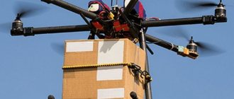
Another obvious method of using a drone is to carry any cargo through the air. The aircraft is not afraid of bad roads or their complete absence, and remote control allows it to be used in any weather without risking the life of the pilot.
Quadcopter with cargo
There are also non-obvious ways to use quadcopters. For example, in some large shopping centers, aircraft of this type replace lighting lamps under the ceiling. The capture is carried out in a special holder, after which the drone rotates, unscrewing the lamp, and transports it to the ground. A whole lamp is installed in it, which moves back through the air with the device and is screwed in. As a result, there is no risk for personnel, and the work is completed.
What do we need?
Before starting work, you need to prepare the following components:
- a set of wires (preferably multi-colored ones to simplify installation);
- lithium batteries (voltage 3.7V);
- transistor ULN2003A Darlington Transistor (more powerful analogues will do);
- Arduino Uno controller;
- MPU-6050 board (combines the functions of an accelerometer and a gyroscope).
Additionally, you will need a 3D printer, or at least access to one, as well as the necessary tools, a lot of curiosity and patience, since not everything can work out the first time.
A different approach
Another approach is software verification. Usually, when hearing these words, people begin to think about abstract monads and academic manuscripts, difficult to read and poorly applicable in practice. But it turned out that not everything is so bad.
First of all, verification is NOT a guarantee that the program does not contain errors, but only a check that the program guarantees certain properties. And it’s up to the programmer to ensure control of the properties in order to get the desired results.
In the case of SPARK, verification basically provides us with guarantees:
- no overflow of arrays and variables
- no overstepping of boundaries in types and ranges
- no dereferencing of NULL pointers
- no exceptions being thrown.
- guarantee that instruments that cannot be verified will not be used.
- guarantee that all invariants that we describe will be satisfied. And we will describe a lot! Cool, right?
To describe invariants, the SPARK language provides special extending language constructs that describe contracts of procedures, data structures, and even loops. The contract can indicate, for example, that a given function cannot access global variables or modify the global state.
SPARK also takes into account the type restrictions that are described in Ada. In the case of normal execution, a type mismatch error will be thrown in Runtime; SPARK allows you to statically prove that type restrictions cannot be violated by any thread of execution.
For example:
Or another example:
The compiler and verifier will not allow you to create code that will lead to the assignment of values that violate constraints and predicates.
A separate advantage of SPARK is that the system allows you to “stretch” guarantees on the program in stages, that is, the program can be partially verified. That is, some modules can be declared verifiable, but some cannot (yet).
SPARK itself divides verification into levels: from “Stone level” through “Bronze” and “Silver” levels to “Gold” and “Platinum”. Each level enhances the guarantees:
| Stone | We basically know what SPARK is |
| Bronze | Stone + verification of execution threads and determinism/lack of uninitialized variables |
| Silver | Bronze + proven absence of runtime errors |
| Gold | Silver + integrity guarantees - non-violation of local and global state invariants |
| Platinum | Gold + functional integrity guarantee |
We settled on the Gold level because our quadcopter is still not a Boeing 777 MAX.
How verification works in SPARK: the prover collects descriptions of contracts and types, generates rules and restrictions based on them, and then transfers them to the solver (SMT - Z3), which checks the feasibility of the restrictions. The prover links the result of the solution to specific lines in which impracticability occurs.
You can read more in [SUG]
