In this step-by-step instruction I will tell you how to make a wall clock with your own hands.
Watch Features:
- Large numbers (each number is approximately equal to the size of an A4 sheet).
- Thin walls (can be inserted into a picture frame).
- Automatic adjustment depending on the brightness of the lighting in the room.
- Dedicated daylight saving time button.
Making a large watch case
It was assumed that the clock would be made so that it could be seen from anywhere in a large room. Visual design was created in Fusion 360. Electronics in Eagle, software in Bascom.
First, using a homemade CNC milling machine, grooves were milled out on a wooden board, into which cut LED strips were placed, two LEDs in each. That is, two LEDs for each display segment. Then all the cut pieces were connected with thin wires.
Then the CNC came to the rescue again. We cut holes from foamed PVC for all segments of the display. Two plates 5 mm thick and one 1 mm. Finally, cut the plexiglass to size.
The assembly proceeds in order: a wooden base with LED strips, two 5 mm PVC plates (later I used a light-diffusing filter), then 1 mm PVC painted in black varnish, and finally, plexiglass tinted with car windshield foil. Tighten all this together with decorative screws. On the same milling machine we cut out the electronics housing, as well as the handle for wall mounting.
Add a link to a discussion of the article on the forum
RadioKot >Schemes >Digital devices >Household appliances >
| Article tags: | Add a tag |
Large LED clock
Author: Arseniy Virachev aka *Trigger* Published 04/10/2012 Created with the help of KotoEd.
Introduction.
It all started like this. At my dacha I had an old mechanical alarm clock (made in USSR), which had mechanical problems. I decided to build an electronic watch. The first problem is which indicator to choose. VLI and GRI are not suitable due to large temperature differences at the dacha. The LCD is no longer needed for the same reason. The LED indicator remains. I'm tired of looking at small numbers on indicators, and large seven-segment indicators are rare and expensive. It was decided to make an indicator with a digit height of 50mm from individual green LEDs.
We figured out the indicator, but it needs to be managed somehow. In this case, the clock should run even if there is no power for a long time. We will do it on an ATTiny2313 MK and an RTC DS1307 chip, which also has a built-in power controller and allows you to connect a battery.
1. Indicator.
We will make it, as I already said, from individual green LEDs with a diameter of 5mm. Here is the indicator diagram:
There's not much to explain here. Current-limiting resistors, diodes are needed for beautiful drawing of numbers. Each rectangle in the diagram must have one digit (the diagram is the same for all), with a separating colon in the middle.
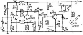
2. Main part.
The circuit, as I already said, is based on ATTiny2313 and DS1307. Here she is:
This requires some explanation. On the right are two dual seven-segment LEDs and two LEDs - the internal circuit of a small indicator with OA. Why two indicators? At night, a large indicator with a bright glow can interfere with sleep (the clock will be near the bed), so the indication can be switched to a small indicator using switch SW1. In the “Night” position A small indicator works in the “Day” position. - big. I took this small indicator out of the washing machine; the pinout is on the stove. 3V battery, CR2032. Transistors Q1-Q4 can be replaced with any other low-power PNP transistors, for example KT315. Q6-Q9 - on PNP with a CE current of at least 1A, Q5 - on NPN with a collector current of at least 0.4A. The power supply can be any with a voltage of 9-20V, the polarity is not important, you can even use alternating voltage. Current not less than 1A. The U4 stabilizer must be installed on the radiator. By the way, the lower the input voltage, the easier life is for the stabilizer. My BP is like this:
Now let's move on to assembly.
3. Assembly.
Let's go to the store and buy parts.
We make boards and start soldering. Soldering 88 LEDs, the same number of resistors and 44 diodes is not easy, but it’s worth it.
Now we connect everything with wires. I use PLS/PBS cables and connectors. These pictures will help you:
Now we are flashing the MK. Here are the fuses:
And turn on:
The buttons and connectors I used were:
4. Body.
I made the body from plywood and a 20*40 block, sanded it and varnished it. I installed two fasteners on the back for wall mounting.
By the way, to seal the indicator windows I used film from green bottles, it looks beautiful and protects from sun exposure.
Now some photos:
5. Management.
In normal mode, the dots flash in turn. To set the time, press Mode. The dots will light up. Now you can use the Set button to set the clock. Press the Mode button again. The dots will go out. Use the Set button to set the minutes. Click Mode. The dots will flash and the clock will start running.
Conclusion.
There is still 40% of memory left in the MK. You can't add a thermometer, but an alarm clock is quite possible. Perhaps I will do it someday.
Printed circuit boards in SL5.0 and MK firmware are below:
Files:
MK firmware, *hex Indicator board Main board
All questions in the Forum.
| What do you think of this article? | Did this device work for you? | |
| 48 | 28 | 15 |
| 1 | 2 |
DIY LED clock on Arduino WS2812 controlled (addressable)
After another upgrade of my 3D printer . By the way, I will post an article and video on upgrading Anet 8A soon.
So what am I talking about? Oh yes. And so I decided to print flat and large parts. They were the ones that came off my 3D printer. It even happened to come off along with the tape.
New version of the Clock!
I found a model of an LED clock . You can download the model from the author's page.
For the project, it is advisable to take an Arduino Nano and a DS3231 .
Assembling a clock using Arduino and WS2812 addressable LEDs:
1. We print all the parts on a 3D printer .
2. Glue the LED strip onto 2 plates and solder them in a zigzag.
3. Install the gratings on top of the tape. We get this result.
4. We put everything into the watch case and fasten everything with M3 screws.
5. We install the mount for the legs and fasten the legs.
6. Connect the electronics according to the diagram.
7. Load the firmware into Arduino . The author uses Arduino Pro Mini , I decided to use Arduino NANO v2 (ATmega168) .
I didn’t like the author’s firmware and decided to completely rewrite it. Due to the fact that the clock only has 5 lines . Then standard libraries for displaying text on a matrix were not suitable. And I had to create each symbol .
As a result, the watch had the following capabilities:
1. Setting the dial color.
2. Change brightness 10 modes.
3. Display the current date in the form of a creeping line.
4. Saving all settings into non-volatile memory. When you turn off the watch, all settings are saved.
5. The real-time clock module, equipped with an additional battery, allows you to store the current date and time without depending on the availability of power on the device itself.
6. Firmware downgraded on Arduino Nano V2.0 (ATmega168) . When increasing the functionality of the clock, you must use Arduino Nano V3.0 (ATmega328) .
Due to the fact that I used Arduino Nano V2.0 (ATmega168), it will not be possible to further expand the functionality. No free memory. But if you install Arduino Nano V3.0 (ATmega328) which has 2 times more memory . Accordingly, the functionality can be expanded:
1. Make auto brightness adjustment. By installing a photo resistor.
2. Install the speaker and write the alarm settings.
3. You can add a strobe to the alarm functions. Flash just white or like a police siren, one side is blue, the other is red.
4. Change the Arduino Nano to a NodeMCU and control the clock via a smartphone. Display the weather and exchange rates. They rudely tell me to create an informer. But since the watch display is not very large. Much information will not be very readable.
The author of the case has modified versions of the clock. For example, the stand is made larger and the watch is more stable. There are also covers that cover the wires from the back.
More photos on the project can be found here: DIY LED clock on Arduino WS2312
Don't forget to subscribe to the Youtube channel and join groups on VKontakte and Facebook.
Bye-bye everyone. And see you in the next project.
Did you like the article? Share it with your friends:
Downloads
| Clock_v1.ino | 10 Kb | 1044 | You can download the file. |