The operating principle of a static electricity generator (also called electrophore machines) is that the disks rotate relative to each other in opposite directions and create positive and negative charges. When the disks rotate, as charges accumulate, a discharge occurs - lightning between the electrodes.
What is an electrophore machine and how does it work?
A Wimshurst generator or electrophore machine is an induction electrostatic device designed as a continuous source of electrical energy. In the 21st century, it is used as an auxiliary technique for demonstrating physical experiments concerning various electrical effects and phenomena.
A little history of the invention
In 1865, experimental physicist from Germany August Toepler developed the final drawings of an electrophore machine. At the same time, the second independent discovery of a similar unit was made by the German scientist Wilhelm Holtz. The main difference of the device was the ability to obtain greater power and potential difference. Holtz is considered the creator of a source of direct electric current.
The simple initial design for using an electrophore machine was improved in 1883 by James Whimshurst from England. Its modification is used in all physics laboratories for visual demonstration of experiments.
What are Leiden banks
The first electrical capacitor, created by Dutch scientists Pieter van Musschenbroek, was a Leyden jar. The invented capacitor has the shape of a cylinder with a wide or medium neck of different diameters. The Leyden jar is made of glass. It is covered inside and outside with special sheet tin. The product is covered with a wooden lid. The main function of the invention is the accumulation and storage of large charges.
The creation of such a jar was stimulated by the extensive study of electricity, the general speed of its propagation, as well as the electrical conductivity properties of various materials. Thanks to her, it was possible to produce an electric spark artificially for the first time. Now Leyden jars are used only as an integral part of electrophore machines.
Further reading[edit]
- Gottlieb Christoph Bohnenberger [de]: Beschreibung unterschiedlicher Elektrizitätsverdoppler von einer neuen Einrichtung nebst einer Anzahl von Versuchen üb. verschiedene Gegenstände d. Elektrizitätslehre [Description of the various electricity doublers of the new device, along with a number of experiments with various objects of electricity] Tübingen 1798.
- Holtz, W. (1865). "Ueber eine neue Elektrisirmaschine" [About the new electric machine]. Annalen der Physik und Chemie
(in German).
Wiley. 202
(9):157–171. DOI: 10.1002/andp.18652020911. ISSN 0003-3804. - Wilhelm Holtz: higher charge of insulating surfaces due to lateral tension and transfer of this principle to the design of induction machines. In: Johann Poggendorff, K.G. Barth (ed.): Annals of Physics and Chemistry. 130, Leipzig 1867, pp. 128 - 136
- Wilhelm Holtz: Influence machine. In: F. Poske (ed.): Annals of Physics and Chemistry. Julius Springer, Berlin 1904 (seventeenth year, fourth edition).
- O. Lehmann: Physical technique of Dr. J. Frick. 2, Friedrich Vieweg und Sohn, Braunschweig 1909, p. 797 (Section 2).
- F. Poske: New forms of machines of influence.. In: F. Poske (ed.) For physical and chemical education. Julius Springer magazine, Berlin 1893 (seventh year, second issue).
- Stong, "Electrostatic motors are powered by the Earth's electric field." October 1974 (PDF)
- Oleg D. Efimenko. " Electrostatic Motors: History, Types and Operating Principles
". Electret Scientific, Star City, 1973. - G. W. Francis (author) and Oleg D. Efimenko (editor), " Electrostatic Experiments: An Encyclopedia of Early Electrostatic Experiments, Demonstrations, Devices and Apparatus
." Electret scientific, Star City, 2005. - W. E. Johnson, " Modern High Speed Impact Machines;
their principles, design and applications in radiography, radiotelegraphy, spark photography, electroculture, electrotherapy, high voltage gas ignition and materials testing ." ISBN B0000EFPCO - Simon, Alfred W. (November 1, 1924). "A quantitative theory of the influence of an electrostatic generator". Physical Review
.
American Physical Society (APS). 24
(6):690–696. DOI: 10.1103/Physrev.24.690. ISSN 0031-899X. PMC 1085669. PMID 16576822. - J. Clerk Maxwell, A Treatise of Electricity and Magnetism (2nd ed., Oxford, 1881), vol. ip 294
- Joseph David Everett, Electricity
(an expansion of Part III of Augustin Privat-Deschanel's Natural Philosophy) (London, 1901), ch. iv. paragraph 20 - A. Winkelmann, Handbuch der Physik (Breslau, 1905), vol. iv. pp. 50–58 (contains a large number of links to original articles).
- J. Gray, " Electrical Impact Machines, Their Historical Development and Modern Forms [with Instructions for Making Them]
" (London, 1903). (JAF) - Sylvanus P. Thompson, Nicholson's Influence Machine-1788–1888, Journ. Soc. Tel. Eng., 1888, 17, p. 569
- John Munro, History of Electricity (The Project Gutenberg Etext)
- HELL. Moore (ed.), Electrostatics and Its Applications
. Wiley, New York, 1973. - Oleg Dmitrievich Efimenko (together with D.K. Walker), “ Electrostatic motors
”. Phys. Learn. 9, 121–129 (1971). - Pidgeon, W. R. (1892). "The Influence Machine". Proceedings of the London Physical Society
.
IOP Publishing. 12
(1):406–411. DOI: 10.1088/1478-7814/12/1/327. ISSN 1478-7814. - Pidgeon, W. R. (1897). "Influence machine" Proceedings of the London Physical Society
.
IOP Publishing. 16
(1):253–257. DOI: 10.1088/1478-7814/16/1/330. ISSN 1478-7814.
The essence of the electrophore machine
Assembling the Wimshurst machine
In this video tutorial we will assemble an electrophore machine, which is a static electricity generator. At the beginning, general questions about the purpose and design of this machine are discussed, then all the steps for making it yourself are shown in detail.
Check out the selection of hand generators at this Chinese store.
What is an electrophore machine?
The device consists of a base on which its parts are attached. It also includes two racks with axles on which two disks with a metallized coating are mounted. There are also two Leyden jars, which are essentially capacitors or stores of charged particles. Dischargers, which function as the charge of the capacitors accumulate, remove charged particles from the front and rear sides of the disks. The discs are driven by a belt drive. We turn the handle and due to this, the disks rotate.
The first static electricity generators were simultaneously invented in Germany at the same time by August Toepler and, independently of him, by Wilhelm Goltz. The operating principle of an electrophore machine. As the disks rotate relative to each other in opposite directions, they create positive and negative charges. As the disks rotate, as charges accumulate, a discharge occurs.
The authors of the video decided to make this machine, which can be repeated with your own hands in normal home conditions. There are several examples on websites on the Internet of creating such a generator, but this design will have an engine.
First, drawings of the future machine were made. First of all, the disk parameters were calculated. After the preliminary work was done, we began to create the device.
Main details
The machine will consist of the following elements. These are 2 disks that will rotate in opposite directions, they will be made from CDs. Two motors from a computer cooler that will drive them. The disk will be glued with double-sided tape to the motor rotor. The engine itself is attached to the rack. The stands will be made of plexiglass. Leyden jars will also be used. This is an empty metal container from which there is one contact, then a polystyrene dielectric and a brass contact.
Manufacturing of electrophore machine
First you need to remove the coating from the disk to get a transparent blank. To do this we use a stationery knife. To create a working disk, you need sketches, they are made on a computer. The petal template can be made from a suitable material; a bank card is good for this.
Now, using the template, we begin marking on the tape. We attach the template and cut out all the necessary fragments. A total of 20 petals were cut out onto one disk. There should be 20 sections. The angle between the two petals is 18 degrees. Marking is done using a regular checkered sheet and a protractor. Now we place the disk exactly in the middle of the coordinates, using a knife or awl to make notches of 18 degrees. Glue the petals according to the lines. The second disc was made in exact analogy with the first disc. It has been machined to provide clearance.
Remove the yellow wire from the motor. We cut off the stiffeners so that the engine can be disconnected. Some space must be left for mounting holes.
Subscribe to comments Comments (69)
Another thing is that, according to rumors from those who tried to work with e-bay, they are not friendly with our payment systems. If anyone has a positive experience, please share!
Another thing is that, according to rumors from those who tried to work with e-bay, they are not friendly with our payment systems. If anyone has a positive experience, please share!
With the tacit (yet?) consent of the moderator, I am providing a link.
Nice stuff. It's a pity I didn't know about them before. By the way, how do these specific ultrasonic devices work through the overlap, can anyone answer me? Otherwise, people will buy it, and then everything will be useless.
The property of concrete to conduct mechanical vibrations well, including sound vibrations, is one of the secondary reasons for the very existence of this site. The primary reason, naturally, is the tanners, the bitches, I hate neighbors. So everyone will get their nuts. In the description of the devices, I did not find any mention of frequency characteristics, but looking at the size of the diffuser of the powerful version and its rigidity suggest ultrasound. For our purposes, infrasound is preferable, but if you trust the sellers about the predicted special effects, then maybe it will do.
Nice stuff. It's a pity I didn't know about them before. By the way, how do these specific ultrasonic devices work through the overlap, can anyone answer me? Otherwise, people will buy it, and then everything will be useless.
I propose to push the ethical side of the issue aside, because it is enough to make an elementary psychological portrait: 1 of who may be on such forums (scoundrels are usually interested in other methods and they DO NOT ASK THESE QUESTIONS.) 2 if people on their own want to at least somehow change the influence society in their lives, they are clearly aware of what they want and do not see any other ways. 3 We ourselves don’t know MUCH how much we are rabbits for those who already have these technologies and are far from at the everyday level.
With the tacit (yet?) consent of the moderator, I am providing a link.
you will read one more post below and draw a conclusion. If it’s too difficult (for tankers), then I’ll chew it later.
I looked at the topic that you SS pointed out - I re-read everything, the summary: from the category - around the bush. (links with files are not readable, the generator may work, or maybe not.)
a good device for overclocking demos :)
theorist, damn it. When the neighbors start harming your brain, for about six months, come in and let’s have some fun.
I respect people like spn123!
One request - don't interrupt the topic.
FreeX - if you have the brains to bring an article from the Criminal Code - take the trouble to think further - before writing!!
People, please, does anyone have a file with infrasound? Share, I don’t have any strength anymore: my neighbor got me, she won’t let me and my mother live.
Tell me, if I record infrasound on a tape recorder, will it work? Thank you in advance.
Well, let's chew it, otherwise you're tired of jokes
https://www.svetozor.ru/soft/Mozgoprav/help/Audio.php
you will read one more post below and draw a conclusion. If it’s too difficult (for tankers), then I’ll chew it later.
2 FreeX 1 learn to read. 2. Read
I would not recommend you to use such terrorist methods as innocent people will suffer, including you (Shahid blah)
In the late 60s, French researcher Gavreau discovered that infrasound of certain frequencies can cause anxiety and restlessness in humans.
Infrasound with a frequency of 7 Hz is lethal to humans.
Sources of infrasound on land can include compressors, internal combustion engines, moving vehicles, industrial air conditioners and fans.
Medium-intensity fluctuations can cause digestive, cardiovascular, respiratory, and mental disorders with the most unexpected consequences.
Natural (resonant) frequencies of some parts of the human body.
• 20-30 Hz (head resonance) • 40-100 Hz (eye resonance) • 0.5-13 Hz (vestibular resonance) • 4-6 Hz (heart resonance) • 2-3 Hz (stomach resonance) • 2-4 Hz (gut resonance) • 6-8 Hz (kidney resonance) • 2-5 Hz (arm resonance)
Federal Law of July 26, 2001 N 103-FZ “On introducing amendments to Article 6 of the Federal Law “On Weapons”
Adopted by the State Duma on June 28, 2001
Article 2. This Federal Law comes into force on the date of its official publication.
President of Russian Federation
_______________________From this it turns out_____________________
Article 111. Intentional infliction of grievous bodily harm
Article 105. Murder
shall be punished by imprisonment for a term of eight to twenty years, or the death penalty or life imprisonment.
And so that it turns out you want the Criminal Code of the Russian Federation Article 105 part 2 points a, c, e, d + Criminal Code of the Russian Federation Article 111 part 2 points b, c part 3 point b. I think they'll give you a hell of a lot and more. ___________________________________________________________
DON'T DIG A HOLE FOR OTHERS YOU WILL FALL INTO IT YOURSELF
It’s better to read and relax If your neighbor is annoying you.
Source
Fundamental laws of electromechanical energy conversion in inductive machines
Ampere's law
According to Ampere's law, a force acts on a current-carrying conductor in a magnetic field
- where F – force, N,
- I – current strength, A,
- – conductor length, m,
- B—magnetic induction, T,
- — angle between the direction of the current and the magnetic induction vector, degrees.
The direction of this force is determined by the “left hand” rule.
Faraday's law of electromagnetic induction
The discovery of electromagnetic induction in 1831 by Faraday is one of the fundamental discoveries in electrodynamics. Maxwell owns the following in-depth formulation of the law of electromagnetic induction:
Any change in the magnetic field over time excites an electric field in the surrounding space. The circulation of the strength vector E of this field along any fixed closed contour s is determined by the expression [3] [4]
- where E – electric field strength, V/m,
- ds – contour element, m,
- Ф - magnetic flux, Wb,
- t—time, s
The electromotive force of induction arising in a closed loop is equal to the rate of change in time of the flux of magnetic induction
- where is the electromotive force of induction, V
The “-” sign shows that the induced current arising in a closed conducting circuit has such a direction that the magnetic field it creates counteracts the change in the magnetic flux that caused the current.
Electrophoric machine (Wimshurst generator) Wimshurst
The Wimshurst generator is an induction electrostatic machine. In it, a static charge is formed not through triboelectricity when friction is present, but through the induction of charges. This class of machines has higher efficiency compared to those that use friction.
Description of the Wimshurst machine
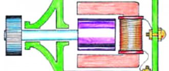
The machine consists of two disks, which are made of a good dielectric, such as ebonite, acrylic, etc. These discs are loosely mounted on an axle and can rotate around a horizontal axis. The disks themselves are arranged vertically. Using handle 1, both disks are rotated in different directions. One disk rotates clockwise and the other counterclockwise. This is achieved using drive belts 2 and 3, one of which is twisted 180° on one of the pulleys. This ensures multidirectional rotation of the disks, which is necessary for the induction of charges. Both discs rotate from the same handle and will therefore rotate simultaneously.
Metal strips 4 are glued to the outer part of each disk, which do not touch the edges of the disk, but are made at some distance from them. The stripes are arranged radially, in the form of rays emanating from the center of the disk. Both disks have the same number and arrangement of stripes; one can say that one disk is a reflection of the other.
When the disks rotate, the strips come into contact with brushes 5, which act as a contact for transferring charge along conductors 6, 7, 8 and 9. When operating the Wimshurst machine, the metal strips at the point of contact with the brushes can wear out and structurally this wear should be kept to a minimum, and Maximum contact reliability. Conductors 6 and 7 serve to remove and accumulate generated charges from both disks. Conductors 8 and 9 are each located on one side of the disk and connect diametrically opposite strips.
Thus we have two types of conductors. Some (6 and 7) are for removing charges, and 8 and 9 are for establishing a kind of “ground” - a line of neutral potential. Conductors 6 and 7 are located on the same geometric diametrical axis relative to the disks, and conductors 8 and 9 are rotated at an angle of 90° relative to each other.
You can also notice that between conductors 8 and 9, conductors 6 and 7 are located in the middle and are spaced at an angle of 45°. Thus, we see that the machine is structurally symmetrical and simple enough to make it yourself.
Description of the operation of the electrophore machine
When the handle is rotated, the discs begin to move in opposite directions.
Brushes, which are usually made in the form of tinsel, begin to come into contact first with one and then with subsequent metal strips.
With each revolution, more and more charge begins to accumulate, which ensures an increase in the potential on pins 6 and 7. For better accumulation, capacitors in the form of Leyden jars are used.
As soon as the accumulated charge reaches the maximum value for the Wimshurst machine design used, further charge growth stops. The larger the diameter of the disks and the higher the rotation speed, the greater the charge the electrophore machine can generate.
How does charge accumulation occur?
Let's assume that the first circle has a lack of free charges, which in our case means a lack of free electrons in the metal plates. When the second disk moves, its plates will alternately come into contact with the brushes on conductor 8, and, accordingly, an excess of free charge carriers will be formed on them.
This happens because the plates on both sides, between which the dielectric (the material of the disks) is located, are a flat capacitor, but a capacitor whose plates move. The electric charge on such a capacitor is induced, or in other words, induced.
Then the following happens. The plates of the second disk, having reached the brushes of contact 6, will give their electrons to a storage device in the form of a Leyden jar (capacitor). This Leyden jar will accumulate a charge -Q. Then it will be the turn of the next plates and so on. A similar process occurs on the first disk, since it also rotates, but in a different direction. Here we can say that free carriers are, as it were, pumped out of another Leyden jar, thereby forming a lack of electrons on it, which means it acquires a +Q charge.
The more often the plates of both disks come into contact with the brushes on conductors 6 and 7, the greater the amount of charges accumulates on them. Leyden jars, if installed, will charge more and more until Coulomb forces begin to resist further accumulation of charges. This means that there is an accumulation limit, which can also be characterized by the potential difference (voltage) between the two contacts 6 and 7.
If you subsequently discharge both contacts that have accumulated +Q and -Q, either onto each other, or transfer the charge to another electrical capacitance, then further accumulation of charge will become possible again.
You can ask. Where does the initial charge come from? The point is that it always exists. Any two conductors separated by a dielectric (gas, liquid, solid) always have a capacitance, and moreover, they have a potential difference, which indicates the presence of more free charge carriers on one such conductor than on the other.
The Wimshurst electrophoric machine is a self-excited machine, that is, it does not require the supply of any additional charge to start its operation.
Is the Wimshurst machine a power generator?
More precisely, we can say that the Wimshurst machine is a converter of mechanical rotational energy into the energy of an electrostatic field. When operating such a machine, like any other, there are friction losses, energy leaks, etc. Therefore, its efficiency cannot be more than 100%, and even it cannot be equal to 100%.
As the potential difference grows, the more charge accumulates, the stronger the Coulomb forces will counteract the mechanical ones. In practice, this means that with each revolution of the discs the applied force will increase. In addition, there will be friction losses in the structure and unwanted charge leakage.
Links[edit]
- Cm .:
- Heathcote, N. H. de V. (1950) "Guericke's ball of sulfur", Annals of Science
,
6
: 293-305. DOI: 10.1080/00033795000201981
Zeitler
die
Schwefelkugel", Monumenta Guerickiana 20/21 : 147-156. - Heathcote, N. H. de V. (1950) "Guericke's ball of sulfur", Annals of Science
- Schiffer, Michael Bryan (2003). Draw the Lightning: Benjamin Franklin and Electrical Technology in the Age of Enlightenment. Univ. California Press. pp. 18 -19. ISBN 0-520-24829-5.
- Optics, 8th request
- Hauksbee, Francis (1709). Psychomechanical experiments on various objects
. R. Brugis. - Pumfrey, Stephen (May 2009). "Hawkesby, Francis (b. 1660, d. 1713)". Oxford Dictionary of National Biography
(online ed.). Oxford University Press. DOI: 10.1093 / ref: odnb / 12618. Retrieved December 11, 2011. (Subscription or UK public library membership required.) - Consult Dr. Carpue's Introduction "to Electricity and Galvanism", London 1803.
- Mawer, William, Jr.: "Electricity, Its History and Progress", Encyclopedia Americana; Library of Universal Knowledge, vol. X, pp. 172 ff. (1918). New York: Encyclopedia Americana Corp.
- Ronalds, B. F. (2016). Sir Francis Ronalds: Father of the Electric Telegraph
. London: Imperial College Press. ISBN 978-1-78326-917-4. - Ronalds, B. F. (2016). "Sir Francis Ronalds and the Electric Telegraph". Int. J. For the History of Engineering and Technology
.
86
: 42–55. DOI: 10.1080/17581206.2015.1119481. - De Queiroz, A. S (2014). "The Operation of the Wimshurst Machine".
- Massachusetts Institute of Technology (2010). "MIT Physics Demonstration - Wimshurst Machine".
Weisstein, E. W. (1996–2007). "The Wimshurst machine - from the world of physics by Eric Weisstein".
- Von Slatt, J (2012). “Jake Wimshurst's car and how to build it! (Part 1)" .
- Bonetti, “Une machine électrostatique, genre Wimshurst, chopped secteurs et invisible” [Electrostatic machines of the Wimshurst type, without visible sectors], French patent no. 232,623 (issued September 5, 1893). See: Description of machines and processes for lectures on inventions ont été pris
... (Description of machines and processes for which invention patents have been obtained...), 2nd series, vol. 87, part 2 (1893), section: Instruments de précision: Production et transport de l'électricité, p. 87. - See also:
- (Anon.) (April 14, 1894) "Machines d'induction électrostatique sans secteurs" (Electrostatic induction machines without sectors), La Nature
,
22
(1089): 305-306.
English translation of the La Nature
(see above): (Anon.) (26 May 1894) "Electrostatic Induction Machines Without Sectors",
Scientific American
,
70
(21): 325-326. - (Anon.) (April 14, 1894) "Machines d'induction électrostatique sans secteurs" (Electrostatic induction machines without sectors), La Nature
- CM. Keenan (August 1897) "Wimshurst Sectorless Machines", American Electrician
,
9
(8): 316-317. - Assembly instructions for the Bonetti machine
- G. Pellissier (1891) "Theory of the Wimshurst machine" (Theory of the Wimshurt machine), Journal de Physique théoretique et appliquée
, 2nd series,
10
(1): 414-419.
On page 418, French lighting engineer Georges Pellissier describes what is essentially a Bonetti machine: “ ...la machine de Wimshurst pourrait, en effet, être construite avec des plateaus de verre unis et des peignes au leu de brosses aux extrémités des diamétraux.
L'amorçage. au départ devrait être fait à l'aide d'une source étrangère, placée, par example, en face de A 1, à l'extérieur. "(... A Wimshurst machine, in fact, can be constructed from simple glass plates and with combs instead of brushes at the ends of the diametral conductors. The initial charging can be carried out using an external source located, for example, opposite and outside [section] A 1 [glass disk].) Pellissier then states that "the role of the metal sectors of the Wimshurst machine seems primarily to be to facilitate its automatic starting and to reduce the influence of atmospheric humidity." - Van de Graaff, RJ; Compton, K.T.; Van Atta, L. C. (February 1933). "High Voltage Electrostatic Generation for Nuclear Research" (PDF). Physical Review
.
American Physical Society. 43
(3): 149–157. Authorization code: 1933PhRv…43..149V. DOI: 10.1103/PhysRev.43.149. Retrieved August 31, 2015. - landartgenerator (April 13, 2013). "EWICON (Electrostatic Wind Energy Converter)". landartgenerator.org
. Retrieved February 26, 2015. - How long should we wait for a bladeless windmill?
- Dutch Windwheel 2.0: Herontwerp zonder windenergie?
- Dutch wind wheel
Goltz electrophore machine
The historical period of the most active experimental research in the field of electrical phenomena is associated with the advent of the first electrostatic machines, the action of which made it possible to obtain electrical energy through the performance of mechanical work.
Mechanical work consisted in the rotation of certain parts of the machine, during which the forces of attraction (opposite) and repulsion (of the same name) of electric charges present on the electrified elements of the machine were overcome.
Experiments with such machines contributed to a better understanding by researchers of that time of the very nature of electricity and the principles of electrical interactions.
Historians attribute the creation of the first electrostatic friction machine to the German scientist Otto von Guericke, who first created such a device in 1650. It was a machine whose operation was based on the then already known phenomenon of electrification of bodies by friction. However, friction machines had a significant drawback - their operation required the application of large mechanical forces.
Unlike friction machines, the electrophoric (induction) machines created later were free of this drawback, since in order to obtain electrical energy they did not need direct contact of the electrified parts with the inductor (with the part that caused the electrification).
Thus, the first electrophoric machine, that is, an electrostatic machine that did not require mutual friction of its parts to obtain electrification, was built in 1865 by the German physicist August Toepler. The inventor was of the opinion that it was electrophore machines that would make it possible to efficiently generate electricity through the conversion of mechanical energy.
Around this time, the German physicist Wilhelm Holtz, independently of Toepler, designed a simpler and more efficient electrophore machine that produced a larger potential difference, and could even serve as a source of direct current for lighting purposes. It was Goltz’s machines that became the first electrophore machines that appeared in the classrooms of educational institutions.
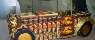
The main parts of the Goltz machine are two glass disks and metal combs designed to remove the charge. One of the disks is fixed, while the other can rotate. The disks are mounted on a common axis. In one museum exhibit, the stationary disk has a diameter of 100 cm, while the rotating disk has a diameter of 94 cm.
The fixed disk rests on an ebonite plate and is supported in a vertical position by ebonite circles on insulating stands. Windows are cut out in the fixed disk, on the back of which incomplete paper sectors called frames are glued.
The frames end in paper tongues, the front pointed edges of which are directed towards the movable disk and are slightly curved. The discs, frames and tongues are coated with gum lac (a resinous substance).
Along the horizontal diameter of the movable disk, in front, on each of its sides, brass combs are installed. These combs are connected to corresponding brass conductors, at the ends of which conductive balls are installed, through which brass rods pass, ending with balls on the inside and wooden (insulating) handles on the outside. The rods can be moved, moving the balls further or closer.
Leyden jars (inner plates) can be connected to the conductors, the outer plates of which are connected to each other by a conductor. Two brass posts at the front of the machine are used to connect wires; balls can be leaned against these posts by simply tilting the conductors.
The front disk is driven into rotation by means of a belt drive and a system of pulleys connected to a handle, with the help of which the experimenter sets this mechanism in motion. However, before you start working with the machine, it is necessary to electrify the paper sectors (frames) with opposite charges (let’s denote them as p+ and p-).
These frames, being charged, due to the phenomenon of electrostatic induction, will act on the rotating disk, and the disk, in turn, will influence the combs O and O'.
As the disk rotates, the frame (in window F) with charge p+ will induce (induce) a negative charge on the back of m of the rotating disk, and a charge of the same sign will be attracted from the comb O, again due to the phenomenon of electrostatic induction. Part of the disk m' will receive a negative charge from the comb O, and the comb O itself, together with its conductor C and the ball r, will therefore become positively charged.
So, the disk was electrified negatively on both sides (in places m and m'), and the conductor on the left side of the machine was positively electrified. The disk continues to rotate, and now, parts of its surface m and m' approach the window F', located on the stationary disk on the right.
The influence of the frame installed here with a negative charge p- is enhanced by the surface m', which means that a positive charge will be attracted from the comb O' towards the disk. Accordingly, both the conductor C' and the ball r' will be negatively charged. Surface m takes on a positive charge attracted from the comb. The disk continues to rotate and the cycle repeats.
Electrostatic generators are considered the most ancient sources of electrical voltage: How electrostatic generators are designed and work
Advanced science and devices[edit]
These generators have been used, sometimes inappropriately and with some controversy, to support various fringe scientific research. In 1911, George Samuel Piggott received a patent for a compact double machine, enclosed in a sealed box, for his experiments in radiotelegraphy and "anti-gravity". Much later (in the 1960s), a machine known as the "Testatika" was built by the German engineer Paul Suisse Baumann and promoted by the Swiss community Methernithans. Testatika is an electromagnetic generator based on the 1898 Pidgeon electrostatic machine that claims to produce "free energy" available directly from the environment.
DIY electrostatic generator
How to clean a dishwasher at home: cleaning tips
The operating principle of a static electricity generator (also called electrophore machines) is that the disks rotate relative to each other in opposite directions and create positive and negative charges. When the disks rotate, as charges accumulate, a discharge occurs—lightning between the electrodes.
How it works - theory
The rotation of disks with metal sectors leads to the transfer of electrical charge inside the machine, which is stored in capacitors until a spark or leakage charge occurs.
How to enter symbols and signs on a computer keyboard?! Read also:
The neutralizer does the following: it drags the charge from one half of the disk to the other and the disk is not just charged, but selectively charged - not over the entire plane.
In other words, the disk collects charges from the air, and the neutralizers redistribute them. The charge is removed by the brush, moves along the conductor to the opposite brush, and at the moment when a segment of the second disk appears opposite the segment, it jumps to it.
Next, this segment approaches the brush of the second neutralizer and the process is repeated, but on another disk. Thus, a circulation of charges occurs between the disks, during which the air between the segments is ionized and separated. As a result of pumping, the voltage increases; in addition, the machine has the effect of moving the capacitor plates apart, which also helps to increase the voltage.
A miniature device for creating such harmless lightning (but not for microelectronics) is easy to make with your own hands.
101 ideas to beautifully arrange slices for the holiday tableRead also:
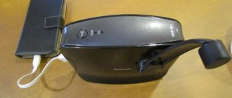
This electrostatic generator is capable of generating over 20,000 volts, but the low current makes it safe to use without special precautions.
Device characteristics
- Height: about 140mm
- Width: approximately 120 mm
- Power: 3V 0.3A
- Static charge: 20 kV
- Disc diameter: 120 mm
There is no need to turn anything by hand (as was the case in the prototype of the century before last) - everything is done by 2 electric motors. Just press the power button and wait a while until the charge accumulates on the electrodes.
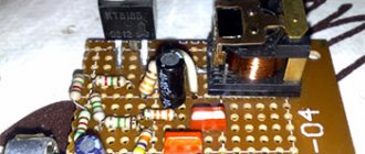
Materials and components
You will need for installation: a soldering iron and solder, a screwdriver and pliers. Two motors from old CD players and all sorts of small fastenings.
The generator runs on two AA batteries and is capable of creating discharges 2 cm long. The most difficult thing here is the 120 mm discs. They need to be made according to this principle: take two laser discs from a CD or DVD. Glue the segments with aluminum tape (25 sectors). Glue the discs to the motors. Make brushes from aluminum strips.
If everything is done and configured as necessary, the spark will reach a size of about 20 mm, and the discharge will strike every 0.5 seconds.
CONTENT
- 1 Description 1.1 Friction machines 1.1.1 History
- 1.1.2 Friction mode
- 1.2.1 History 1.2.1.1 Goltz machine
- 1.3.1 Van de Graaff
Project “Assembling an electrophore machine”
Introduction
In the 21st century, it is used as an auxiliary technique for demonstrating physical experiments concerning various electrical effects and phenomena, so we decided to assemble it ourselves.
Wilhelm Holtz electrophore machine
Hypothesis. We assume that a working electrophore machine can be created at home
Purpose of work: Assemble an electrophore machine.
Study and analyze literature on the history of the invention of the electrophore machine;
Compare the advantages and disadvantages of various types of electrophore machines;
Formulate the operating principle of an electrophore machine;
Assemble an electrophore machine;
Give recommendations for assembling an electrophore machine.
Build process
Vinyl records, 2 pcs;
Glass jars 2 pcs;
Contacts for fastening wires;
Bolts with nuts;
Paper cutter;
Phillips screwdriver and regular screwdriver;
Description of machine assembly:
We take two vinyl records of the same diameter; a static charge will form on them.
We mark the plate into an even number of segments.
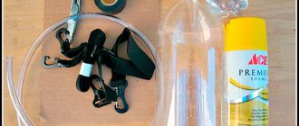
We glue aluminum petals on each side of the plate. Total needed - 32 pieces
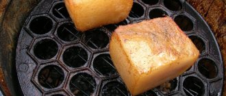
We make Leyden jars. Using aluminum tape, we cover two-thirds of the glass jar, inside and outside.
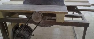
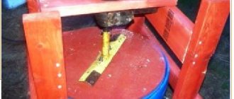
Using a jigsaw and a milling machine, we cut out the main wooden parts: stand, wooden stands, pulleys, handle for rotation. Using wood glue, glue the pulley parts together.
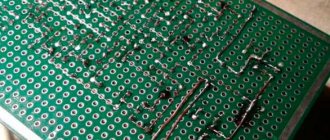
We saw the brass tube into segments 30 cm long. Using a sharp nail, we punched holes into which we will later insert nails that play the role of a collector. We bend the brass tube in the shape of a horseshoe. In the other two brass tubes, we insert the wire of the telephone cable, cleared of braid, into the holes on both sides. They will act as brushes in the neutralizer.
We assemble the entire structure using bolts with a diameter of 8 and a length of 120 mm. In accordance with the resulting distance between the posts, we fix them on the stand using wood glue.
Let's drill the bolts and secure the brass manifold tubes in them using wire. We secure the lower part of the bolt in the lid of the Leyden jar with nuts, through a body washer (for stability). We will place a chain under the bottom nut, long enough for it to be in stable contact with the bottom of the can. Let's install the cans with the collectors attached to them on an aluminum strip and secure it with a glue gun so that the collector's horseshoe is located symmetrically relative to the disks. Insert nails into the punched holes, with a minimum gap relative to the disk. To make the spark gap, two brass tubes and balls covered with aluminum foil were required; later, two parts with rounded cones were found in the tools, which replaced the balls. Textile hair bands were used for pulley belts. The tubes were insulated with blue and red electrical tape.
Work in thermodynamics
In thermodynamics, the work done by a gas during expansion is calculated as the integral of pressure over volume:
A1→2=∫V1V2PdV.{displaystyle A_{1rightarrow 2}=int limits _{V_{1}}^{V_{2}}PdV.}
The work done on the gas coincides with this expression in absolute value, but is opposite in sign.
- A natural generalization of this formula is applicable not only to processes where pressure is a single-valued function of volume, but also to any process (represented by any curve in the PV plane), in particular, to cyclic processes.
- In principle, the formula is applicable not only to gas, but also to anything capable of exerting pressure (it is only necessary that the pressure in the vessel be the same everywhere, which is implicit in the formula).
This formula is directly related to mechanical work. Indeed, let's try to write the mechanical work during expansion of the vessel, taking into account that the gas pressure force will be directed perpendicular to each elementary area, equal to the product of pressure P
on the area dS of the platform, and then the work done by the gas to displace h one such elementary platform will be dA=PdSh.{displaystyle dA=PdSh.} It can be seen that this is the product of pressure and the increment in volume near this elementary platform. And summing over all dS
, we get the final result, where there will be a full increase in volume, as in the main formula of the section.
Neighbors are doing renovations
All repair work is a separate topic. When carrying out work using a drill, a person honestly thinks that he is not doing anything wrong, since it is working time, and therefore the law is not being violated.
But in some cases, this kind of noise can disturb an old woman who has a migraine and wake up a small child. In this case, you cannot complain, since the law has not actually been broken.
If the person is well-mannered, then you can independently decide on the time for him to carry out the noisiest repair work, which will give you the opportunity to go for a walk with your child during this period of time or not to go to bed at this time, but simply reschedule it.