A generator that produces electrical energy through rotation (mechanical energy) is called a dynamo. Due to its properties, the direct current generated by it is not used in everyday life as often as alternating current. All power plants are equipped with giant alternating current generators (alternators). Despite this, the dynamo remains a relevant device that serves well in some electrical fields, for example, when charging batteries. Therefore, a small generator assembled with your own hands will always find a use.
DIY dynamo, its elements
In order to build a dynamo, you will need such basic elements as a housing, a rotating armature, a commutator, a brush holder, brushes, and insulated copper wire.
Let's consider the preparation of each element separately.
| Dynamo device |
| There are different options for making the case. A tin can or a piece of pipe (diameter 100 mm) is suitable for it. First, you need to cut out the bottom of the can and weight the body. To do this, wrap a strip of iron of the same width very tightly in several rows on the inside or outside of the can. Then we rivet or solder the strip to the body. Secondly, we make cores for electromagnets and shoes for them from tin or iron. We take strips of tin along the width of the body, bend them, place them on top of each other, fasten them with iron wire and solder them along the sides. We attach the cores to the holes in the housing located opposite each other. Read also: Does your business need a chatbot? Using screws, screw the body to the block (wooden or metal). In the housing we make two bearing strips (brass or thick sheet metal, size 110x20 mm) and a stand (80x20 mm) to secure the armature. We solder the strips in a cross pattern and make a hole in the center along the diameter of the axis. The same hole in the rack 10 mm from the end. Copper tubes (10-15 mm with a diameter of 8 mm) can be soldered into the bearing holes. We solder the first bearing to the body with the ends of the strips, after which the system will bend outward. |
| The anchor must be made carefully, since it largely determines how the dynamo will work. You can assemble an anchor from tin plates. The thickness of all plates must be equal to the thickness of the body (50 mm); their manufacture requires special precision. Approximately 120 circles (46 mm in diameter) will have to be cut out of iron. We divide each circle into eight sectors using a compass, make markings through the center of the circle, and in the center of the circles we draw two circles with a diameter of 8 and 38 mm. At the intersection of the large circle with the sector lines, we draw another 8 mm circles. On all round plates, where the circles are drawn, we accurately drill eight 8 mm holes. We tightly fasten the plates with nuts and put them on the axle, you should get an anchor with round longitudinal grooves. We round off sharp corners in the grooves with a file. |
Dynamo machine (Bike generator). Types and features. Job
An electrical energy generator is a device that converts chemical, mechanical or thermal energy into electrical current. Such a generator, used on bicycles to power the rear lights and headlight, is a dynamo.
Flaws
- Difficult setup. Careful adjustment and adjustment of the wheel's contact with the tire at a certain angle, tire pressure, and height is required. If the bike is dropped or the retaining screws become loose, the alternator may be damaged. An incorrectly adjusted generator device will make a lot of noise, create excessive resistance, and slip on the wheel. If the fastening screws are too loose, the mechanism may move out of place and get caught in the wheel spokes, which will lead to broken spokes and failure of the bicycle wheel. Some bicycle generators are equipped with special loops that prevent them from getting into the spokes.
- Switching requires physical effort. To activate the generator, it is necessary to move its housing until it comes into contact with the wheel. Bushing generators can be switched on automatically or electronically. You don't need to put any effort into this.
- Increased noise. During operation, a humming noise is heard, while hub dynamos do not create noise.
- Wheel tire wear. To operate the generator, contact with the tire is required, resulting in friction and tire wear. If you compare it with a dynamo hub, there is no friction with the tire.
- Resistance to movement. A bottle dynamo offers significantly more resistance to the bike's movement than a hub model. However, when configured correctly, the resistance is negligible, and when switched off, there is no resistance.
- Slipping. In wet, rainy weather, the drive roller of the bottle generator will slide on the tire tire, which reduces the generation of electric current and reduces the brightness of the headlight and taillight. Hub generators do not require good tire grip to operate and are not affected by weather or other adverse conditions.
Dynamo hub
The hub design of the bicycle generator was developed in England and produced by various companies in many countries. The power of this design can reach 3 watts at a voltage of 6 volts.
Their manufacturing technologies are constantly being improved, the dimensions of the structure are becoming smaller and more powerful.
Flashing red signals of this traffic light:
Correct 8. Traffic regulation
8.7.6. To regulate traffic at railway crossings, traffic lights with two red signals or one white-lunar and two red ones are used, having the following meanings:
a) flashing red signals prohibit the movement of vehicles through the crossing;
b) a flashing white-lunar signal indicates that the alarm system is working and does not prohibit vehicle movement.
At railway crossings, simultaneously with the prohibitory traffic light signal, an audible signal may be turned on, additionally informing road users that movement through the crossing is prohibited.
Wrong 8. Traffic control
8.7.6. To regulate traffic at railway crossings, traffic lights with two red signals or one white-lunar and two red ones are used, having the following meanings:
a) flashing red signals prohibit the movement of vehicles through the crossing;
b) a flashing white-lunar signal indicates that the alarm system is working and does not prohibit vehicle movement.
At railway crossings, simultaneously with the prohibitory traffic light signal, an audible signal may be turned on, additionally informing road users that movement through the crossing is prohibited.
- Task 13 of 15
Story[
Jedlik Dynamo[
In 1827, Hungarian physicist Anjos Istvan Jedlik began experimenting with electromagnetic rotating devices, which he called electromagnetic self-rotating rotors. In the prototype of his unipolar electric motor (completed between 1853 and 1856), both the stationary and rotating parts were electromagnetic. He formulated the concept of a dynamo at least 6 years before Siemens and Wheatstone, but did not patent the invention because he thought he was not the first to do so. The essence of his idea was to use, instead of permanent magnets, two oppositely located electromagnets, which created a magnetic field around the rotor. Jedlik's invention was decades ahead of his time.
Faraday disk[
Faraday's Disc In 1831, Michael Faraday discovered the principle of operation of electromagnetic generators. The principle, later called Faraday's law, was that a potential difference was formed between the ends of a conductor that moved perpendicular to a magnetic field. He also built the first electromagnetic generator, called a Faraday disk, which was a unipolar generator using a copper disk rotating between the poles of a horseshoe magnet. It produced a small constant voltage and a high current.
The design was imperfect because the current self-closed through areas of the disk that were not in the magnetic field. The stray current limited the power drawn from the contact wires and caused unnecessary heating of the copper disk. Later, homopolar generators solved this problem by placing many small magnets around the disk, distributed around the entire perimeter of the disk to create a uniform field and current in only one direction.
Another disadvantage was that the output voltage was very small because only one turn around the magnetic flux was formed. Experiments showed that by using many turns of wire in a coil, the higher voltage often required could be obtained. Wire windings became the main characteristic feature of all subsequent generator developments.
However, recent advances (rare earth magnets) have made unipolar motors with a magnet on the rotor possible, and should bring many improvements to older designs.
Dynamo machine[
Dynamos are no longer used to generate electricity due to their size and the complexity of the switches. This large belt-drive, high-current dynamo produced 310 amperes of current and 7 volts or 2,170 watts when spinning at 1,400 rpm. Main article: Dynamo
The dynamo was the first electrical generator capable of generating power for industry. Its operation is based on the laws of electromagnetism to convert mechanical energy into pulsating direct current. Direct current was generated through the use of a mechanical commutator. The first dynamo was built by Hippolyte Pixie in 1832.
Having gone through a series of less significant discoveries, the dynamo became the prototype from which further inventions emerged, such as the direct current motor, alternating current generator, synchronous motor, and rotary converter.
A dynamo consists of a stator, which creates a constant magnetic field, and a set of windings that rotate in this field. On small machines, a constant magnetic field could be created using permanent magnets; on large machines, a constant magnetic field is created by one or more electromagnets, the windings of which are usually called field windings.
Large, powerful dynamos are rarely seen today, due to the greater versatility of using alternating current in power networks and electronic solid-state DC-to-AC converters. However, before alternating current was discovered, huge dynamos producing direct current were the only way to generate electricity. Dynamos are now a rarity.
Reversibility of electric machines
The Russian scientist E. H. Lenz pointed out the reversibility of electric machines back in 1833: the same machine can work as an electric motor if it is powered with current, and can serve as a generator of electric current if its rotor is set in rotation by some motor, for example steam engine. In 1838, Lenz, one of the members of the commission to test the action of the Jacobi electric motor, experimentally proved the reversibility of the electric machine.
The first electric current generator, based on the phenomenon of electromagnetic induction, was built in 1832 by Parisian technicians the Pixin brothers. This generator was difficult to use, since it was necessary to rotate a heavy permanent magnet so that an alternating electric current would arise in two wire coils fixed motionless near its poles. The generator was equipped with a device for rectifying the current. In an effort to increase the power of electric machines, inventors increased the number of magnets and coils. One such machine, built in 1843, was the Emil Stehrer generator. This machine had three strong moving magnets and six coils that rotated by hand around a vertical axis. Thus, at the first stage of the development of electromagnetic current generators (before 1851), permanent magnets were used to produce a magnetic field. At the second stage (1851-1867), generators were created in which permanent magnets were replaced with electromagnets to increase power. Their winding was powered by current from an independent small current generator with permanent magnets. A similar machine was created by the Englishman Henry Wilde in 1863.
During the operation of this machine, it turned out that generators, while supplying electricity to the consumer, can simultaneously supply current to their own magnets. It turned out that the cores of electromagnets retain residual magnetism after turning off the current. Thanks to this, the self-excited generator produces current even when it is started from a state of rest. In 1866-1867, a number of inventors received patents for self-excited machines.
In 1870, the Belgian Zenob Gramm, working in France, created a generator that was widely used in industry. In his dynamo, he used the principle of self-excitation and improved the ring armature, invented back in 1860 by A. Pacinotti.
In one of Gram's first machines, a ring armature mounted on a horizontal shaft rotated between the pole pieces of two electromagnets. The armature was driven into rotation through a drive pulley, the windings of the electromagnets were connected in series with the armature winding. The Gram generator provided a direct current, which was discharged using metal brushes sliding along the surface of the commutator. At the Vienna International Exhibition in 1873, two identical Gram machines were demonstrated, connected by wires 1 kilometer long. One of the machines was driven by an internal combustion engine and served as a generator of electrical energy. The second machine received electrical energy through wires from the first and, working like an engine, drove the pump. It was a spectacular demonstration of the reversibility of electrical machines, discovered by Lenz, and a demonstration of the principle of energy transfer over distance.
Before the connection between electricity and magnetism was discovered, electrostatic generators were used, which operated based on the principles of electrostatics. They could produce high voltage, but had little current. Their work was based on the use of electrified belts, plates and disks to transfer electrical charges from one electrode to another. Charges were generated using one of two principles:
- electrostatic induction
- triboelectric effect, in which an electric charge arose due to mechanical contact of two dielectrics
Due to low efficiency and difficulties in insulating machines that generate high voltages, electrostatic generators were of low power and were never used to generate electricity on an industrial scale. Examples of machines of this kind that have survived to this day are the electrophore machine and the Van de Graaff generator.
Other electrical generators using rotation[
Without a commutator, a dynamo is an example of an alternator. With an electromechanical commutator, the dynamo is a classic DC generator. The alternator must always have a constant rotor speed and be synchronized with other generators in the power distribution network. A DC generator can operate at any rotor frequency within its permissible limits, but produces direct current.
MHD generator[
A magnetohydrodynamic generator directly generates electricity from the energy of a plasma or other similar conducting medium (for example, a liquid electrolyte) moving through a magnetic field without the use of rotating parts. The development of this type of generator began because its output produces high-temperature combustion products that can be used to heat steam in combined cycle power plants and thus increase overall efficiency. The MHD generator is a reversible device, that is, it can also be used as a motor.
Mini power plant
The invasion of electricity on board the car began with the starting device - the starter. This device required a good “charge” of electricity, because its task was to spin the heavy flywheel, and with it the crankshaft with connecting rods and pistons, overcoming the compression resistance in the cylinders. Anyone who has ever turned the starting handle of a motor knows how hard this work is.
The battery turned out to be a reliable source of electricity for the starter. But its energy reserve was constantly decreasing, and not only with each successive start of the engine: when recoil was not required, the battery discharged itself, requiring constant recharging. The idea of a miniature on-board power station was proposed by the famous German engineer-inventor Robert Bosch. It was he who, at the beginning of the twentieth century, developed the principles on the basis of which generators operate in modern cars.
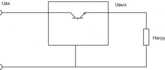
In the past, these devices were called dynamos, or simply dynamos. The essence of their work was as follows. Due to the rotation of the rotor in the magnetic field of the stator, the mini-power plant generates electric current. But according to the laws of physics, this current turns out to be alternating, while automotive devices require constant current. A set of diodes (more often called a diode bridge) converts one into another in the generator. But that's not all. Automotive devices are designed to be powered by a current of a certain voltage, and its stabilization (maintaining the voltage within the established limits) is monitored by a special device - a relay regulator.
How does the power supply system of modern cars work? During the process of starting the engine, only the battery is involved; the generator is “sleeping” during these moments. It turns on when the engine crankshaft begins to rotate smoothly. This rotation is transmitted to the generator rotor using a belt. Some companies (for example, Mercedes-Benz) use one belt that connects up to a dozen pulleys - the coolant pump, power steering, air conditioning compressor and other devices, plus tension and idler rollers. Other companies (seen on Hyundai engines) sometimes use three belts connecting different units. But with any scheme, all devices are driven into rotation from a pulley on the toe of the engine crankshaft, and one of the belts necessarily transmits rotation to the generator rotor.
Sometimes the location of the generator is also curious. In most cases, manufacturers try to place this device higher so that it does not get exposed to water and dirt, which inevitably penetrate into the engine compartment when driving. In principle, a generator is a very reliable device that can serve for years and even decades. At the same time, its safety should not be neglected.
Another significant point is the simplicity (or complexity) of checking the drive belt tension and replacing it. Correct belt tension is the key to reliable operation of the generator. If the tension is weak, the device may not produce the required voltage; if the tension is too strong, the bearings in which the rotor shaft rotates will quickly fail, which will manifest itself as a howling or whistling sound. Most cars today use automatic belt tensioning devices, but on older models you can still find designs that require manual application. How to check if the belt is tensioned correctly? Press your thumb with a force of approximately 1 kg on the middle of the longest branch of the belt, the deflection should be no more than 10 mm. Of course, the tension should be checked with the engine stopped.
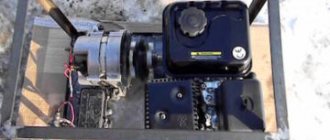
Powerful DIY generator
A powerful electricity generator can be assembled using an old bicycle without eights on the rear wheel. A 28-inch wheel and a 52-tooth front sprocket will do, but other options are possible, such as a 26-inch and a 46-tooth sprocket. First of all, we remove unnecessary parts: the front wheel, tires, gear shift, brakes. Place the bike on the stand.
The generator must be self-contained with two large terminals and one small one. We connect the two large terminals together to form a plus, and the small one with an indicator light. We connect the grounding terminal to the housing (minus). We clean the generator and remove the cooling fan from it. We fix the generator on a bracket behind the seat, the spindle should be outside 10-12 cm from the rim. We select a belt, preferably a toothed one, with a circumference of approximately 82 inches. For 26" wheels, A78 belts are suitable, and for 27" wheels - A80.
To adjust the tension of the alternator, we use a spring-type tensioner. The belt does not need to be tightened too much as the torque is quite low. We attach a voltmeter, a switch and a light bulb to the steering wheel. If there are children in the house, it is necessary to protect the moving parts of the mechanism to eliminate the possibility of injury.
Test stand.
Three generators tested (from left to right): Busch + Müller Dymotec6, AXA HR and one cheap Chinese one.
- B&M Dymotec6 has good mechanics. It runs well on the tire. It can often be found on quality touring bikes. In 2004, this dynamo could be purchased for 24.90 euros.
- AXA HR is equipped with strong magnets. Of all the tested generators, it produces the highest current. To limit the output voltage, two reference diodes (BZX 85C 7V5) connected in series are provided. Before taking measurements, we opened the plastic case and removed these diodes. It is often installed on bicycles from well-known manufacturers. Price AXA HR 16.99 euros.
- The cheap Chinese dynamo has slightly worse magnetic characteristics than the Dymotec6. The mechanics are not designed for intensive use, but they meet all standards. It is held together with two screws and can be completely disassembled. It is usually equipped with Auchan bikes. It may be useful for cyclists who rarely ride in the dark, as it can be purchased for only 3.45 euros.
Should I connect one or two headlights to the hub dynamo?
At speeds above 25 km, any hub dynamo can be used to power two headlights connected in series. Many long-distance cyclists use two headlights. If two headlights can provide good illumination, then the additional weight and drag is not so important. The E6's single headlight provided ample illumination even in tandem during the Paris-Brest-Paris cycling marathon at 70 km/h on unfamiliar, challenging roads. Those who do decide to install two headlights may benefit slightly from using the SON20's lower resistance hub dynamo.
Manufacturing of commutator and brush holder
When assembling the dynamo, in particular the commutator and brush holders, attention and accuracy are required.
| The collector can be made of a tube (copper, brass) or assembled from plates. You will need a tube with a diameter of 20-25 mm and a length of 25-30 mm, which is sawn into 4 equal parts. Two two-millimeter holes are drilled into the plates. Then we cut out a cylinder (diameter 20-25 mm, length 25 mm) from fiber or ebonite, dry wood will also do. We make a hole in the center of the cylinder so that it can fit tightly onto the armature axis. We attach the plates to the cylinder using small screws, each time leaving a space of 1-2 mm between them. You can use twisted wire and insulating tape. The screws should not touch the axle, otherwise there will be a short circuit. We fill the gaps between the plates with rosin. |
| A brush holder with brushes is used to relieve stress in the commutator. The brushes must extend and rotate around the axis of the armature to change the force and angle of pressure on the commutator. The base, 10 mm thick, will be made of fiber, ebonite or paraffin wood. Let's drill three holes in it so that the two outer ones will fit the bolts. We take copper bolts or 35 mm radio contacts. We screw in the bolts securing the brushes with nuts for clamping. The hole in the center should be equal to the diameter of the copper tube that was used for the first bearing in the housing. Opposite the central hole in the end of the block, we drill a through hole and make a thread for the fastening screw. We take a screw (for wood - a screw) with a slot or edges on the head. Make a hole slightly smaller than the diameter of the screw, screw in the screw. First screw it in 2-3 turns, then turn it out, repeating until it fits in three turns freely. Then we process the next pass with the same screw. We make a bearing frame, drill a hole in the upper end of which, insert a piece of copper tube and solder it. Brushes can be made in different ways, from copper, brass plates or carbon brushes. These can be plates 40-50 mm long with a cross-section of 10-15 mm. At the end of the brush we drill an oblong through hole 20 mm long for the bolts. This hole will allow you to change the pressure, bringing the brushes closer to the commutator. We secure the brushes with washers. To ensure that the brushes touch the commutator tightly, we sharpen their ends obliquely. |
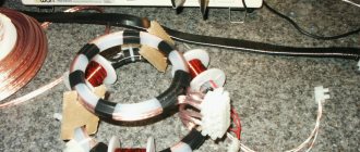
Winding
For the winding we will use copper wire with paper insulation with a cross section of 0.5-0.8 mm. You need to purchase half a kilogram of wire, the thickness of which will affect the voltage and current. For example, when winding with 0.5 mm wire, 25 volts will be generated at a current of 1 ampere, if you take a wire of 0.8 - 8 volts at a current of 3 amperes. Before starting work, divide the wire into two parts. To wind the electromagnet you will need 450 g of 0.5 wire and 60 g for the armature winding. If you bought 0.8 wire, we will set aside 430 g for the electromagnet, and 70 g for the armature.
Dynamo assembly
The dynamo is assembled with your own hands in several stages:
- For the base we will prepare a board measuring 150x200 mm, 30 mm thick. Let's drill two holes from the edges of the electromagnet ring.
- We fasten the housing to the base with two screws so that the electromagnets are located on the same horizontal line opposite each other.
- We place wooden blocks on the sides of the body so that it sits firmly and screw them to the base.
- Then we pass the free end of the armature axis through the bearing on the housing. We insert it into place between the electromagnets.
- We put a brush holder with brushes on the bearing of the bearing frame from the inside and insert the end of the armature axis with the commutator. A thick metal washer or wire ring must first be placed on the collector.
- We install the armature so that when it rotates between the electromagnets, it does not touch them and is at the same distance from them. The stand is attached to the base with two screws.
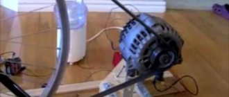
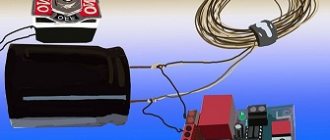
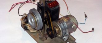
: Collecting spare parts
If you want to build a dynamo machine with your own hands, then you will need a few things. Here is their list:
Electronics:
- 1x stepper motor - I got mine from an old printer
- 8 diodes - I used a personal power unit used 1N4001
- 1x Voltage Regulator – LM317T
- 1x Development board with PCB
- 2 resistors - 150 Ohm and 220 Ohm
- 1x radiator
- 1x Battery connector
- Solid wire
- Insulation tape
Mechanical parts:
- 1x Bike Reflector Holder - I removed this from the bike when I connected the lights.
- Aluminum corner blank, you will need a piece approximately 15 cm long
- Small nuts and bolts - I used printer screws and some other used parts
- Small rubber wheel - attaches to the stepper motor and rubs against the wheel as it rotates.
Tools:
- Dremel - It's not entirely necessary, but it makes your life a lot easier.
- Drills and bits
- File
- Screwdrivers, wrenches
- A breadboard for testing the circuit before you put everything on the bike.
- Multimeter
Transplantation of "organs"
On older cars, sometimes it comes down to replacing the alternator assembly. As we have already said, this is a reliable and durable device. Graphite brushes are the first to fail, but the brush assembly (usually combined with a voltage regulator) is usually inexpensive and easy to change (sometimes even without removing the generator from the car). But if the mileage exceeds two or three hundred thousand kilometers, you can expect surprises from the generator. So, on one of the removed devices we found wear... on the copper slip rings on the rotor shaft. This cannot be repaired.
A new generator for a domestic car will cost an average of 60–70 dollars, for a foreign car – three to five times more expensive. Sometimes it is possible to find a non-original, cheaper device instead of a “original” device. But often a failed imported generator can be replaced with a Russian product that is suitable for the location and other parameters.
Somehow I managed to perform such an operation. I sharpened the “ears” of our generator housing so that they coincided with the mounting location on the foreign car. I moved the pulley from a foreign generator to a Russian one. The diameters of the shafts of the two devices coincided down to microns, but we had to tinker with installing the pulley strictly in the same plane with other drive pulleys (otherwise rapid wear and breakage of the belt would have been inevitable). I connected the wires, started the engine, and the battery was charged again. As it turned out later, the masters of our car service centers often resort to such “transplants” on old foreign cars. And their owners not only save on the purchase of new generators, but often also receive additional power from mini-power plants. And given the abundance of electrical systems on cars, it is never superfluous.
Who invented the dynamo and how does it work?
In 1831, the English physicist Faraday discovered an unusual electromagnetic phenomenon. An electromagnetic field arose in the copper wire during rotation between the magnetic poles. It was this that excited the movement of electrons along the conductor. Based on research, the physicist formulated the law of electromagnetic induction. The conductor was a copper wire wound onto a metal rod with a magnetic property. When the magnetic particles in the rod were aligned with the poles, it turned into a magnet and attracted metal objects to itself. To magnetize the rod, you can use a coil or a permanent magnet. The effect occurs when one electromagnet rotates strongly around another.
In the same year, a device for converting electrical energy into mechanical energy appeared. The first electric motors resembled steam engines: only electromagnets were installed instead of cylinders, and metal armatures were installed instead of pistons.
In 1834, Russian academician Boris Jacobi created the first electric motor with a rotating armature. Four years later, the academician used an improved electric motor on the world's first motor boat. The world's first alternating current generator was built by Pavel Yablochkov. And the invention of another Russian scientist M. Dolivo-Dovolsky - a three-phase current generator - was truly revolutionary.
Hub dynamos are heavier than bottle dynamos
Bottle Dynamos can slip when wet (meaning your lights may not be reliable), although this rarely happens when set up correctly.
Hub dynamos cost more because you have to buy or build the wheel. However, they don't require mounting brackets on the bike, and the wheels probably aren't as expensive as you think.
Bottle dynamos are much easier to convert to a bike that already has hub or disc brakes, or to a geared rear wheel.
While hub dynamos are made to fit specific wheel sizes (most are designed for 26" or 28" wheels and will produce more drag when used in smaller wheels), bottle dynamos are not specific to wheel size. because they work on the sidewall of the tire and are not affected by wheel speed at all.
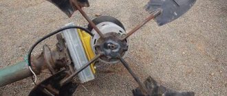
: Motor Installation
The engine mount was made of an aluminum angle and a reflector bracket. To mount the engine, holes were drilled into the aluminum. One side of the corner was then cut out to make room for the wheel.
The wheel was attached by wrapping duct tape around the motor shaft until the connection was tight enough to push the wheel directly onto the duct tape. This method works well, but it needs to be improved in the future.
Once the motor and wheel were attached to the aluminum, I found a good spot on the frame to mount everything. I attached the blank to the seat tube. My bike's frame is 61cm, so the area where the generator is mounted is quite large compared to smaller bikes. Just find the best place on your bike to mount the alternator.
Once I found a suitable location, I made marks for the aluminum bracket with the reflector bracket installed so it could be cut to size. I then drilled holes in the bracket and aluminum and mounted the structure onto the bike.
I finished assembling the 12 volt bicycle generator by attaching the project box to an aluminum mount with two posts.
Dynamo charger
In field conditions, a simple “twist” or dynamo for charging your phone is always useful. Chargers with a built-in battery are popular. There are mechanical chargers that also do not take up much space. Many modern “spinners” are equipped with flashlights.
These devices charge mobile phones quite successfully. For example, when rotating the knob 2-3 revolutions per second, you can get a coefficient value from 0.65 to 2.5. Spin it for a couple of minutes and you can talk on the phone for 2 to 5 minutes. It all depends on the model and reception conditions. A handheld dynamo will not be able to power a powerful smartphone with a large display. Mechanical charging will provide results in conjunction with a simple phone along with a hands-free headset.
Dynamo charging will work effectively when the battery is completely discharged, but you can only increase the phone’s charge by twisting the handle up to 50%. When the battery is only half discharged, the spinner becomes a useless toy. If the instructions indicate a maximum charging current of 400 mA with a power of 2 W, then it will not be possible to squeeze out additional energy even if you quickly rotate the handle.
Dynamo machine for bicycle - description
A small generator is sometimes mounted on a bicycle to provide electricity for lighting at night. The generator is called a bicycle dynamo. Inside the dynamo, a permanent magnet rotates in the middle of some turns of wire. Rotating a magnet instead of coils has the advantage that sliding rings are not needed. A rotating magnet creates a changing magnetic field, and this generates electricity in the coils of wire.
The top of the dynamo is in contact with the rim of the tire, which rotates as the bicycle moves.
What loads is a cyclist allowed to carry?
Correct 6. Requirements for cyclists
6.4. A cyclist may only carry such loads that do not interfere with the operation of the bicycle and do not create obstacles for other road users.
22. Cargo transportation
22.3. Transportation of cargo is permitted provided that it:
b) does not interfere with the stability of the vehicle and does not complicate its control;
Wrong 6. Requirements for cyclists
6.4. A cyclist may only carry such loads that do not interfere with the operation of the bicycle and do not create obstacles for other road users.
22. Cargo transportation
22.3. Transportation of cargo is permitted provided that it:
b) does not interfere with the stability of the vehicle and does not complicate its control;
Electric current in a dynamo
The resulting current in the conductor will have the greatest value provided that the rotor is located perpendicular to the magnetic lines. The greater the turn of the conductor, the less current will be. And vice versa. That is, the process of rotating a conductor in a magnetic field forces the generated electric current to change direction twice during one rotation of the rotor. Thanks to this property, this type of current began to be called alternating. A dynamo for generating direct current is built on the same principle as for alternating current. The difference can only be noticed in the details, when the ends of the metal wire are not fixed to rings, but connected to half rings. Such half-rings are necessarily insulated from each other, which, when the conductor rotates, makes it possible to alternately contact one half-ring and then the other with the brush. This means that the generated current will flow into the brushes exclusively in one direction, in a word - the current will be constant.
How to assemble a dynamo?
A DIY dynamo can be assembled quickly. The basis for the future generator will be a wooden board about 30 mm thick and an area of 150 by 200 mm. The housing is attached to it with two screws so that the electromagnets are positioned horizontally, one against the other. Then, through the bearing attached to the housing, the armature axis is threaded, which is fixed in place between the electromagnets. Brushes are threaded through the inside of the bearing frame and the second end of the armature axis is inserted. The collector is fixed at this end. Before attaching the bearing frame to the base, the armature must be aligned so that its rotation between the electromagnets does not touch them. The brushes should be located across the shoes of the electromagnets and secured to the bearing. A small pulley is attached to the free end of the rotor. Electrical installation of the device consists of connecting the ends of the windings for electromagnets with brushes. Also, pieces of flexible wire are connected to them to communicate the device with an external circuit.
Generator and bicycle
A bicycle dynamo demonstrates its power depending on the rotation speed. For example, not spinning or stopping the bike fast enough will cut off power to a flashlight or other device. But at high speeds, the light bulbs can burn out before their service life. There are several types of bicycle electric generators: The hub type is built into the wheel hub. Structurally, it consists of a static core on an axis and a reversing multi-pole magnet in the shape of a ring. Their cost is higher, which is offset by quiet operation and efficiency. The bottle type is the most popular. The bottle-shaped device is equipped with a small wheel that is driven by friction against the sidewall of the rubber tire of the wheel. The carriage generator is installed next to the carriage cup, below the frame stays. The movement of the spring-loaded roller is due to friction against the tire tread. It should be mentioned that the bottom bracket and bottle dynamo machine will stop working when exposed to wet conditions.
Measurements.
Maximum power of dynamos.
Installation:
Dynamo, Greenacher voltage doubler with two 1N5818 and two 1000uF, load 100 - 250 mA, speedometer connected to the dynamo.
Methodology:
We start the dynamo at 15 km/h. We measure the voltage parallel to the current load 100, 130, 160, 190, 220, 250 mA. Repeat at 40 km/h. Repeat for each dynamo. Knowing the voltage and current, we calculate the power. We build a graph of power and current.
Results:
AXA HR produces maximum power at 200 mA (after voltage doubler), B&M Dymotec6 at 180 mA, cheap dynamo at 160 mA. Regardless of the speed, the AXA HR has the highest power, while the cheap dynamo has the lowest.
Conclusions:
The maximum power is achieved at a certain current; it depends little on the speed, but mainly depends on the dynamo itself. In short: A dynamo is a source of current.
Power and speed of Dymotec6.
The curves for other models are similar to those for Busch&Müller Dymotec6 with the only difference being that the power will be slightly higher or lower.
Installation:
Dymotec6, Greenacher voltage doubler with two 1N5818 and two 1000uF, 180mA load, speedo.
Methodology:
We start the dynamo at 4, 5, 7, 9, 12, 15, 19, 24, 31, 40, 50 km/h and measure the voltage parallel to the load. We calculate the power = measured voltage × 180 mA current for each speed and draw a graph.
Conclusion:
With a well-matched load, the Dymotec6 produces 2.7 watts at medium speed, 5 watts at high speed and 6 watts at very high speed.
These indicators are achieved without changing the dynamo. Question:
Why doesn't the light bulb burn out in a standard 3W headlight connected to a Dymotec6 at a speed of 50 km/h?
Answer:
Because at this speed the load is selected incorrectly (the current is also high) and the light bulb does not consume maximum power.
Question:
Where is energy lost if the load is not drawing the maximum power possible?
Answer:
She doesn't disappear. The dynamo simply rotates with less force. Try to close the dynamo outputs at full speed - the current will drop significantly.
Dymotec6 performance at different temperatures.
As the dynamo operates, its temperature increases. We tested the B+M Dymotec6 at 50 km/h at 23º C. Connected was a Greenacher doubler circuit (two 1N5818 and two 1000uF) and a 180 mA load. The power released at the load was measured. The experiment was carried out on a stationary platform, so the dynamo was not cooled. After approximately 20 minutes, its power decreases from 100% to 80%. After 10 minutes, there is another slight drop in power. After 30 minutes, the temperature of the case was 89º C. It was probably even hotter inside.
Next, we screwed in a regular 80mm computer cooler to simulate the cooling that occurs when riding a bicycle. The power began to increase and eventually reached 89% of the initial value. The temperature stopped at approximately 40ºC.
The Dymotec6 was chosen for this experiment because it has the best mechanics of all the dynamos tested. Nothing happened to it for two hours while producing 5 W of energy at a speed of 50 km/h. Many dynamos cannot withstand this load. Due to high internal temperatures, bearings suffer and wear out quickly. If, during rotation, the magnet comes into contact with the stator, then due to friction the internal temperature sharply increases, which leads to melting of the housing and jamming of the rotor. On our setup this would only result in the motor disconnecting from the dynamo, whereas on a real bicycle the front wheel could suddenly fall apart due to the rotor shaft breaking the tire, rim or spokes. Therefore, it is better to never buy cheap dynamos.