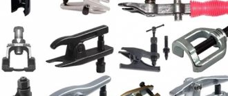
Options
To choose the right bearing puller, you need to know what parameters it must meet.
When purchasing, you should pay attention to the following points:
- Maximum permissible load. This parameter is determined by the strength of the central body of the puller and the power bolt. For mechanical tools, this parameter ranges from 1 to 4 tons. Hydraulic pullers have a force of about 20 tons (but they also have a corresponding price). However, to dismantle elements such as the wheel bearing, mechanical tools are sufficient.
- Working progress. It depends on the reach of the power bolt and the length of the grips.
- Dimensions of the puller legs (in particular, the width and height of the stop).
- Minimum and maximum gripper opening.
With swivel grips
They are more varied in design. The grips in them are locked with bolts.
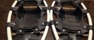
A puller with two rotating double-sided jaws has stops that have different widths at both ends of the jaws. It comes with three rotating one-sided grips; the reach of the grips can be changed by rearranging them. There is also a model that can be used with either two or three rotating single-sided grips. There are 4 points on the body of the puller for installing grips.
Some can be used with an impact (inertial) puller. They can also be used as internal ones, but then the clamp can no longer be used to secure the grips. Crossed grips allow you to change the grip over a wide range. A small (working width up to 50 - 70 mm) tool of simple design, originally intended for removing the ends of battery cables, but is widely used for dismantling various small parts.
Analogue bearings
Which wheel bearing puller to choose or how to make it yourself.
As an alternative, you can consider the products of two manufacturers:
- "Weber", product catalog code - "BR 1118-3020";
- "Pilenga", part number - "PW-P1313".
The products of these companies have proven themselves well. The cost is approximately 1 thousand rubles. The contents are identical to the original delivery.
In practice, it has been revealed that a bearing from a VAZ-2108 may be suitable for the LADA Kalina hub, but it is a few hundredths of a millimeter narrower. Experts do not advise leaning towards this alternative, since there have been cases when the product rotated inside the hub.
Video
This video contains useful tips on how to unscrew the nut securing the pulley to the crankshaft of a car engine.
An option for unscrewing the crankshaft pulley bolt using a poly V-belt.
How to remove the crankshaft pulley on a VAZ (2108, 2109, 21099, 2110, 2111, 2112, 2113, 2114, 2115).
How to remove the crankshaft pulley bolt. Bolted connection.
How to tighten a crankshaft pulley very quickly.
Removes the crankshaft pulley on a Honda car without a special key.
0
Author of the publication
offline for 2 weeks
Mandrel
Universal wheel bearing puller
It is not at all necessary to buy a mandrel; you can make it yourself in a few minutes from a scarce material: from the same bearing that needs to be pressed into place. If you are too lazy to bother, you can buy a mandrel or even buy a whole set and use it for your health. Whatever is more acceptable to you, then choose.
We take an old unnecessary bearing that is still capable of rotating. We bring the bearing to the wheel of the sharpening machine and grind the cage a little: if the bearing is turned across the stone, the work will go much faster
There is no need to sharpen the clip, literally a tenth of a millimeter is enough
We cut out the inner ring by welding
For ease of operation, we weld a washer onto the holder
Types of pullers by type of grip
There are 4 main types available for different types of gripping and dismantling:
- External puller Designed for external dismantling, when the inner ring of the bearing is installed on the shaft, and the outer ring can be grabbed from the outside.
- Internal puller Designed for internal dismantling, where the outer race of the bearing is installed in the housing and the hole in the inner ring can be grasped from the inside.
- Separator puller Designed for dismantling with gripping the bearing from behind using a tension separator, when its rear part is adjacent to the surface and the external type is not suitable.
- Puller with grip between rings Designed for dismantling bearings that are installed simultaneously on the shaft and in the housing, and all other types are unsuitable.
Purpose of the puller
DIY oil filter puller
According to the car's operating manual, problems with how to unscrew the oil filter yourself cannot arise in principle:
- When changing the oil, a new filter is installed;
- the sealing rubber must be lubricated with lithol;
- tighten the consumable element by hand;
- tighten 1/3 turn with slight force.
In this case, the rubber sealing ring does not stick to the ebb of the engine housing; the filter can be removed by hand without a puller. In case of severe contamination of the housing, use a piece of sandpaper - the hand does not slip, the abrasive material ensures reliable grip of the palm on the filter housing.
A piece of sandpaper for unscrewing the oil filter
These requirements are often violated by the users themselves:
- there is no lubrication of the rubber ring; at high pressure and temperature it loses elasticity and sticks to the filter housing and the engine seating surface;
- It is not clear for what purpose the car owner tightens the thread with both hands, tightening it and flattening the rubber seal.
Even in this case, you can try to do without a puller:
- tap the rim in a circle on the side of the sealing ring to ensure its mobility relative to the filter housing or the ebb of the groove of the seating surface;
- pierce the rubber seal with a narrow screwdriver, separating it from the low tide side.
Tapping the rim in a circle
In all other cases, you have to use special devices to twist this consumable item. Since access to the filter is difficult, and its outer size differs on different machines, the question of which puller is better, in principle, does not make sense for the following reasons:
- there are turnkey or head pullers with their own handles;
- some tools are made for a specific filter diameter;
- other pullers have adjustable gripping devices of several sizes;
- Universal sliding devices are suitable for any passenger car filters.
Purpose of the oil filter puller
To purchase or independently manufacture a specific puller model, you should familiarize yourself with the design of each of them.
How to operate a cup puller
Pressing:
- We charge the housing puller.
- Insert the bearing into the hole in the knuckle.
- A washer with the diameter of the body is placed on top.
- We press the housing into the socket until it rests against the locking ring.
Pressing out:
- Use a reverse hammer to knock out the hub.
- On the reverse side we place the washer in the hole.
- Let's skip the rod.
- From the outside we put on a cup larger than the diameter of the fist.
- Rotate the rod clockwise until the remaining ball bearing is completely released.
- Let's analyze the design.
Photo report of the application:
How to unscrew it if it's stuck?
I’ll tell you a few ways that will 100% help you unscrew this element, so here we go:
Trite with your hands. Often you just don’t have enough strength, just call a “more powerful” person and everything can work out. I will say this in 80% of cases they unscrew it by hand. YES, and you need to tighten it again with your hands, tightly! IT'S ENOUGH!
Special key. I already wrote about it once, you can read it here, of course it’s not always at hand, but if you have a friend with a car, he can drive to almost any spare parts store and buy it. I personally even saw it in several supermarkets, the cost is a penny, about 200 - 300 rubles. Everything with it is quite easy and simple, we hook it on and unscrew it, of course, the body of the element will get wrinkled, but actually we don’t need it anymore.
Rope and screwdriver (another lever). Sometimes they also use an old alternator or timing belt. What we do is twist a loop around the filter, tighten it with a screwdriver, tightly. And we try to unscrew it. The main thing is that the rope or belt does not slip.
Next come barbaric but effective methods. The most important thing is that they are dirty, that is, you will get dirty in oil anyway, if you are not afraid, then they are for you.
A hammer and a long, strong screwdriver. Actually, this method is used to unscrew most intractable filter elements. Since the walls of the element are soft, they are usually aluminum, or tin, and other soft metals. It breaks through very easily (just like a tin can). What we do is drive a long and strong screwdriver all the way through, that is, so that it goes in on one side and comes out on the other. And then we unscrew it like a lever. The most important thing is that everything can be done without a special key, and actually using those tools that are always in the garage. The only downside is that your hands are dirty, because some of the oil is always inside.
Hammer and chisel. This is generally the method that they say “ATAS”, there is nothing to explain here, we take a chisel and “fuck” it with a hammer, the most important thing is to hit closer to the bottom, to the place of fastening, and counterclockwise. The case, of course, will be all dented, but the most important thing is to unscrew it. The downside here is not only that you can get dirty, but also that you can hit the engine block with a chisel. I personally recommend the method with a screwdriver, it is still less dangerous.
As you can see, there is nothing complicated, you can do without a special key, just pierce the housing with a screwdriver.
Now we are watching a short video.
And that’s all for me, read our AUTOBLOG.
(17 votes, average: 3.94 out of 5)
Thrust jack and trolley for moving machines
How to move a heavy machine to the workshop?
You can, of course, dismantle the wall or roof, order special equipment (the same crane). But this is all very difficult and time-consuming.
To make your task easier, you can make do with homemade devices. And in this review, the author shows how to make a thrust jack and a trolley with rollers for moving machines.
To make these devices you will need:
- a number of large diameter studs and nuts for them;
- thick-walled channel;
- metal scraps;
- sheet metal;
- tools for work - welding machine, angle grinder (grinder) and marking tool.
Main stages of work
From a piece of channel we cut four identical parts.
In two of them we cut small grooves on the side walls and weld nuts (with a screwed-in pin for better centering).
Approximately in the center of the top shelf we drill a hole equal to the hole of the machine legs. We fix the rollers (wheels) on the stud, clamping them on both sides with nuts.
Next, we will make the trolley itself for transporting the massive machine.
To do this, cut out a square blank from thick sheet iron and round the edges.
We weld the third section of the channel to one edge and weld a pin perpendicular to the side walls of such a length that it does not extend beyond the boundaries of the thrust table.
We drill a hole in the front of the table and prepare the base for the swivel bearing.
We install the fourth piece of channel on this base and engage the wheels. We will install a wheel rotation limiter to prevent them from being worn out.
To lift the machine itself above the ground, we need a hydraulic jack, which can be reinforced with a lifting platform and a thrust platform.
To do this, all supporting parts are cut out of thick iron sheets according to the drawing and welded together.
If everything is done correctly, the jack will fit freely under the machine. Having raised the front part of the machine, we will install a thrust table on wheels under it.
We lift the back part and also install the same wheels that we assembled at the very beginning. We secure everything using bolted connections.
Our homemade product is ready!
For a detailed description and production, see the video below. The idea belongs to the author of the YouTube channel TeraFox.
Not a WEAK device made of channel, profile pipe and metal from the reception!!!!ENG SUB
homemade bearing puller
Really the simplest, self-made bearing puller, we make of old stuff, with our own hands. This video shows and explains how to use improvised means...
Do-it-yourself bearing puller for covers of various parts. Hairpin 16mm. Strip 40/4mm —— Bearing bearing…
A simple homemade puller that allows you to remove bearings located close to the impeller or manifold...
CashBack service LETYSHOPS buy at a discount https://goo.gl/EIqFDX Thank the authors https://www.donationalerts.ru/c/theonlytime PR/Collaboration…
CashBack service LETYSHOPS buy at a discount https://goo.gl/EIqFDX Thank the authors https://www.donationalerts.ru/c/theonlytime PR/Collaboration…
I made a bearing puller out of scrap trash. Metal strip 30×4, two screws with nuts, and a worm...
https://www.youtube.com/watch?v=_BppOE4ydGw Link to Mark Fisher's channel.
Hello, in this video I will show you how to make a beautiful, effective puller for steering wheel ends, made...
The procedure for removing the rear generator bearing using a special puller. The main aspect when…
Generator bearing puller (REVIEW) https://postavto.ru/shop/instrument.
Wheel #Bearing. Wheel bearing puller. The best thanks to the author is DONAT, here...
He showed and explained in detail how to make a simple puller for bearings that cannot be caught on...
Link to website - https://dnipro-m.ua/ Link to channel - https://www.youtube.com/watch?v=SW2tSIbzwJA Hello everyone, friends. Today, together with...
Bearing puller www.avtonabor.com.ua/semniki-podsipnikov.
Universal wheel bearing puller.
I show you how to make a universal homemade puller with your own hands from simple material in just...
Two metal plates 150*30*2.5; stud with nuts; two M8 bolts with nuts; two open-end wrenches 22x24; and steel...
Donat: https://www.donationalerts.ru/r/libral1973 Puller dimensions: https://libral1973.ru/tekhnika/413-s-emnik-svoimi-rukami-razmery-s-emnika.html …
Link to 3D model: https://goo.gl/8dIRYT Detailed 3D model of a universal bearing puller. Even more 3D fashion...
How to make a bearing puller using 4 nuts as a basis. Taking as a basis the part that I made from...
Hi all! I have this set in use. Initially purchased as a “base of mandrels” for a press, for pressing...
One of the ways to make a small puller from scrap materials is considered. More information...
DIY universal puller. A very useful tool in everyday life, especially in the garage.
Repair Izh Planet.
Small bearing puller.
Force 666A035 Bearing puller 19-35 mm My affiliate program on You Tube: https://www.air.io/?page_id=1432&aff=1338.
Replacing a wheel bearing on an ATV without removing the hub.
Dear friend! Jesus wants to save you. Hurry to Him in repentance with faith. The time of grace ends......
Puller from China - https://ali.ski/RDUpK —————————————————————— More Puller - https://ali.ski/wpWi7 ——— —————————…
A simple homemade puller for small bearings. #diy.
This video shows you how to make a small bearing puller yourself.
homemade puller made from trash.
A homemade press for removing and installing bearings on the armatures of power tools, you can remove pulleys...
Another washing machine tank repair. All the time I cut off the clip with a grinding machine. But then I decided to show how...
Powerful wheel bearing remover from garage junk.
DIY puller.
Making a universal CV joint puller from scrap iron. Suitable for all drives...
???? ????? ???? ?? bluestacks clash of clans cihaz?n?z bu surumle uyumlu degil hub serverler sabri agunzagun erkan 1100 dolar iki basamakl? carpma facebook hesap ele gecirme k?rpmadan profil resmi yapmak cam 4 hile sketchup agac ekleme
Universal wheel bearing puller
CV joint puller
A universal puller is a kind of working metal tool that is used to remove and replace wheel bearings. Due to the fact that this puller is universal, it is perfect for servicing many cars, such as:
As well as a large number of other cars from various manufacturers. This is the main difference between a universal puller and others designed for a specific brand of machine.
Manufacturing Features
The manufacturer offers only high-quality bearing pullers made of good material. Production is carried out in accordance with ISO 9001 standard technologies. A mandatory procedure is for the parts of the tool to undergo heat treatment. As a result of this procedure, the wear resistance of the puller increases several times. To combat corrosion of metal parts, a special chemical coating of mandrels and rings is used. Such a complex manufacturing procedure is the key to long service life and proper operation of the device. Moreover, manufacturers offer a wide range of models for different types of cars.
Features of the universal puller
- Among the special characteristics are, first of all, versatility. By purchasing one set of pullers, a car enthusiast gets the opportunity to use it to repair different cars. This characteristic will be especially appreciated by professional craftsmen working in services.
- A universal wheel bearing puller helps in a large number of diverse jobs. It is involved in the installation and dismantling of similar parts, replacing several tools at once.
- The puller is purchased as a kit. There is also a puller screw and a drive handle. In other words, the tool is completely ready for use and you won’t have to buy anything else.
- The removable supports are quite easy to install. To do this, they are installed in the required position for removing the hub. In this case, the circumference of the bolt fastening is no more than 190.2 mm.
Application area
Such a tool for car maintenance will be indispensable, both for personal use and in a car service center. In the latter option, it is simply necessary, as it helps to cope with a large volume of work much faster and with better quality. In this case, labor costs will be minimal.
Using this tool makes it possible to perform many types of car repair and installation work.
With its help, you can remove axle shafts, brake drums, hubs and many other similar parts in a short time. In addition, the pressed brake drums are dismantled.
The cost of such a device is slightly higher than other similar devices aimed at a specific car. However, its scope of application is so wide that it easily compensates for the price.
Homemade gearbox bearing puller: photo of production
Homemade bearing puller for gearbox: photo and detailed description of the homemade product.
The author decided to make a bearing puller with his own hands, we suggest you look at the photo and description of the homemade device.
Materials:
- The puller grips are made of metal square timber - 20 x 20 mm.
- M10 studs, 80 mm long - 2 pcs.
- Plate 12 mm thick.
Tool:
- Welding machine.
- Drill.
- Drills: - M10, M12, M10.5.
- Bulgarian.
- M12 tap.
- Files - rectangular and round.
The puller manufacturing process is as follows:
Take a metal square and cut pieces of 4 cm - 2 pieces. Using a grinder, we grind the shape of the grips into pieces as shown in the photo.
We cut out a groove for the bearing at least 18 mm in height, the hook part will be approximately 3-4 mm thick, and the depth of the groove is approximately 5 mm.
We weld the pins straight to the grips; if the pin becomes crooked, the grips will slide off the bearing.
We drill holes in the plate, one in the middle by 10.5 mm. Next, we drill 4 holes of 10 mm, drilling them so that we can use a file to make two oblong holes of 20 mm each.
The plate initially had a couple of large holes, so we don’t pay attention to them, they don’t interfere with anything.
Plate.
Bearing dimensions:
- Outer diameter 62 mm.
- Inner diameter 25 mm.
- Height 17mm.
To properly drill holes in the plate, you first need to drill a 10.5 mm hole in the center of the plate, then measure in each direction along the radius of the bearing, this turns out to be 31 mm, well, I took 28 for myself so that with this puller I could remove the stuck race on the hub .
Using a round file, I made the holes a little longer so that it would be 68 mm instead of 62 mm. After drilling the holes, take a 12-point tap (see the thread pitch yourself under the central screw) and cut the thread or weld the nut.
Then I took a piece of pipe and a bolt, do it as follows, put a piece of pipe on the shaft, insert a bolt into it, throw a ball from the bearing into the hole and put a puller on top of it all.
Hex screw.
Homemade author: Alexander Govorukhin.
sam-stroitel.com
Materials for production
A bearing is an element that you cannot handle with your bare hands. Therefore, only durable high-alloy steel is used as the manufacturing material. The central body, the power bolt, has even greater strength.
For work you will need the following materials:
- two square metal blanks;
- a pair of steel plates;
- two bolts with nuts;
- release bolt with a working nut of suitable diameter.
Tools: welding machine, grinder, electric drill with a set of drills.
DIY bearing puller | DIY crafts
We continue the series of homemade machines and devices, and this time we will look at how to make a bearing puller with your own hands, photos and videos are attached.
To make a homemade device for bearings, you will need the following materials:
- A pair of wrenches.
- Small metal plates - 4 pcs.
- Threaded stud.
- Bolts and nuts.
The entire process of making a homemade product is shown in detail in these photos. You need to make these blanks from wrenches.
These are bearing grips.
We drill holes in the keys for the bolts.
We will make blanks with holes from the plates.
We weld a knob to the stud at one end and assemble the structure.
This is what the assembled puller looks like.
Operating the device is quite simple, just hook the bearing with the grips, rest the pin in the center and remove the bearing from the axis of the part with rotational movements.
Using this device, you can also remove the inner bearing; insert the pin inside the bearing and screw on the nut.
We put stops and rotate the pin.
This is how we remove the inner bearing from the part.
We recommend watching the author’s video, which shows in detail how to make a bearing puller and the operating principle of a homemade device.
samodelki-n.ru
A simple way to make a homemade removal device
This option is easier to implement, but the product will not be as convenient. You will need the following tools and materials:
- steel pipe, the internal diameter of which will be greater than the diameter of the bearing;
- metal plate more than 5 mm thick;
- Bulgarian;
- stud with nut or bolt with long thread;
- a few nuts.
- Cut a piece of pipe with the required parameters.
Cutting off part of the pipe - We mark all the necessary elements on a metal sheet, outline the pipe and bearing.
Marking out future details - We cut out the parts with a grinder and grind them to meet the exact parameters.
Cut parts - We drill holes for the bolt in the obtained washers.
Drilling holes for bolts - That's it, the remover is ready!
Ready puller
How to make a two-jaw wheel bearing puller: video
Making a bearing puller with your own hands is not at all difficult - you don’t need either expensive materials or specific skills. Using the instructions, you will easily cope with the task and get a useful tool for car repair.
- Author: Dmitry Buimistrov
Hello! My name is Dmitry, I am a journalist by training. I specialize in automotive topics - I started my career in an online store of automotive components, and I myself am a car enthusiast. Rate this article:
- 5
- 4
- 3
- 2
- 1
(10 votes, average: 3.7 out of 5)
Share with your friends!
Kinds
Tools are divided into two groups.
Hydraulic. When they operate, hydraulic traction is used; removal and landing are performed in semi-automatic mode. The main part of such a puller is a hydraulic nut, the internal cavity of which presses on a special piston. This, in turn, transfers the force to the desired part. The hydraulic model is in demand among owners of trucks and other large vehicles - with its help you can easily remove the most massive internal parts.
This is what a hydraulic bearing puller looks like
Mechanical. They operate from human muscular strength and are in demand for mounting/dismounting wheel bearings. There are two-jaw, three-jaw and internal ones. Two-grip ones are the simplest. They are used where maximum process control is needed. Three-jaw machines are equipped with three paws and are used for working with the front hub and generator. Internal options are useful for removing ball and needle roller bearings; in addition, they can be used to dismantle various brass couplings.
Mechanical three-jaw model
Bearing pullers can come in different sizes, but the most popular are universal ones. Their parameters can be adjusted manually, adjusting them to any diameter.
You can make different tools with your own hands, but it is best to make a universal three-jawed version - it is convenient to use.
Diagram of a two-jaw puller
With conical jaw lock
They have two or three grippers and are intended for use in cases where it is necessary to eliminate the asymmetrical load application during dismantling. They provide automatic centering of the jaws using a conical nut that is hand-tightened when the puller is installed. Sometimes this nut is spring loaded.
For external and internal use of such a puller, grippers of different shapes are usually used. Less commonly used is a specially shaped nut that allows the jaws to be reversed so that the puller can be used as an external or internal puller. They are often included in kits along with impact pullers.
DIY wheel bearing puller
To carry out repair work at home, some craftsmen use simple, homemade designs. However, it is always compatible with all sizes of journal bearings. Only with those whose diameter does not exceed seven centimeters.
So, how to make a puller for wheel bearings. To do this, you will need a bolt no more than 90–100 mm long, two metal washers, a fastening nut, and a metal spacer. Moreover, the diameter of the spacer must be such that it fits into the hole for fitting the support bearing with minimal clearance. Thus, after dismantling the wheel, it will be necessary to assemble the above puller and begin to tighten the fastening, as a result, part of the support bearing will be on the outside. Then it's a matter of technique.
A homemade wheel bearing puller is applicable for both the front and rear sections of the chassis system of a domestic car. For foreign brands it is better to use the factory version of the equipment.
Jack - car rack
To make this device, you will need a regular hydraulic jack with one vertical rod (bottle type).
Moreover, it is advisable to choose a device model that is capable of providing lifting of the support to a height in the range of 180–340 mm.
You will also need three sections of a square profile of different lengths, which should fit into each other.
Ideally, for this purpose, use profile pipes with dimensions of 50x50 mm, 40x40 mm and 30x30 mm.
Since the gap between the inner walls of the pipes is quite large, two plates of suitable thickness will need to be inserted between them.
Main stages of work
From pieces of plates you need to make an adapter for the bottle jack stop - all the elements are welded together (you can see how to make it in the video). After cleaning the welds, drill a hole with a 12 mm drill.
You need to drill a hole with a diameter of 6.7 mm in the head of the car jack, and then cut the thread with an M8 tap.
Next, we put on the adapter for the stop and secure it with a bolt.
At the next stage, we attach the base of the jack to a rectangular plate using welding.
Next to the jack we attach sections of profile pipe, which are inserted one into the other (do not forget to insert the plates inside to reduce the gap between the walls). You also need to additionally install another stop from a 20x20 mm profile. Holes for the fastener are drilled in the side walls.
Video: how to make a car rack from a jack
JACK-STAND for the car!
DIY bearing puller
The background is this: the vacuum cleaner engine suddenly began to work with extraneous noise. Having disassembled the housing and examined it, it became clear that the upper rotor bearing had collapsed. It is not possible to remove it without a special puller without damaging the rotor, so attempts were made to find a puller from friends, but they were unsuccessful. I considered it a waste of money to buy this tool in a store because it was a one-time job. In the future, this is how it turned out - making a simple puller with your own hands turned out to be very easy. It took 20 minutes of time and a minimum of details. The only condition is the presence of a welding machine and the ability to use it at least a little.
So, in order. There is a motor rotor with bearings, one of which needs to be replaced.
To remove the bearing from the shaft, you need to place some kind of stop under it. Moreover, this stop must be of a certain strength and minimum thickness, since the distance between the bearing and the armature is several millimeters. An ordinary metal washer was suitable for this. So that it can be placed under the bearing, we will make a cutout in it. To do this, hold the washer in a vice and use a grinder to cut out a quarter of its circumference.
We check on the rotor - it fits.
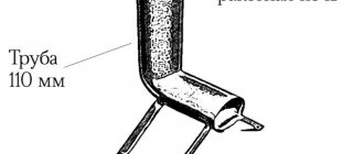
Now let's think about what to make the puller body from. A piece of profile pipe was found in the barn. Let's cut off a 5-centimeter part from it. In order for the puller to be placed under the bearing, it is necessary to cut through one wall of the pipe, and the width of the cut should be greater than the diameter of the bearing. We clamp the pipe in a vice and cut out a strip with a grinder.
Next, we place the pipe on the end, place the prepared washer on it and weld it with electric welding. The connection must be strong so that the washer does not fall off during operation.
We turn the puller body over, installing it with the washer facing down. You need to weld a nut on top into which the bolt will be screwed in order to press out the bearing. The diameter of the nut is smaller than the size of the pipe, so you need to install some kind of support under it. Anything will do: a washer, any plate, a cut pipe wall. In my case, there was no washer of a suitable diameter, so I placed 2 nails under a washer of a smaller diameter and welded them to the puller body. I placed a nut on top and welded everything thoroughly. The bearing puller is ready.
All that remains is to install the puller on the rotor, secure it in a vice, screw the bolt into the nut and, tightening the bolt with a wrench, press out the bearing. The rotor shaft into which the bolt rests has a thread cut. To avoid damaging it, before removing it, you need to screw the nut onto it, and then push the bolt into the nut.
It only took me 20 minutes to make the puller, and in a couple of minutes the bearing was removed from the rotor.
Finally, I’ll show you how to quickly and easily press a new bearing onto a shaft. To do this you will need a vice, a piece of pipe and a washer.
We install the bearing on the shaft, then press the washer against it, then a piece of pipe and clamp this structure in a vice.
When the vice is compressed, the pipe presses on the washer, which presses on the bearing. Under the action of compression force, the part is pressed onto the rotor shaft. The main thing here is to install the structure level, make sure that the rotor shaft fits into the hole of the washer and pipe, and does not rest against their walls, and not bend the rotor with excessive force.
This is how quickly you can make a bearing puller with your own hands, using a minimum of materials, almost free of charge. The design is simple, reliable, and most importantly, it works. The disadvantage of this device is that this puller can only be used for small bearings. For larger ones, it is necessary to make a more powerful design.
Homemade press from a jack with your own hands is simple and affordable
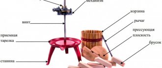
There are plenty of situations in everyday life when it is necessary to squeeze objects with great force.
Here are a few of them:
- Extracting juice from grapes, fruits and vegetables.
- Pressing in or removing silent blocks, bearings, bushings.
- Molding of products using a matrix.
- Bending strong metal workpieces.
- Straightening curved objects.
- The list goes on and on.
For these actions you need a press. The most popular design is hydraulic. The liquid is not compressed, so it is enough to equip a device for compression - pressing with hydraulics, and you can develop virtually unlimited force.
These devices are quite compact. For example, the illustration shows a machine less than a meter high, and it develops a force of up to 10 tons. And it is controlled manually.
Such a press can be bought at a tool store, however, the cost is quite high. If you look closely at the design, you will notice that the power element is very similar to a regular car bottle jack. Therefore, you can make it yourself.
Drawing and concept of a jack press
Power elements are made of steel with a thickness of at least 15 mm, or a steel profile. As vertical posts, you can use a stud, corner, profile pipe, or the same channel.
A threaded rod is preferable because it can be used to quickly adjust the size of the work area.
We will take this diagram as the basis for understanding the design.
Two studs (4) with threads in the lower part (5) into the base (7) , to adjust the height of the upper platform.
The studs (4) are made from a steel circle with a diameter of 30 mm. The upper thread is cut based on the lifting height of the jack rod with a small margin.
A bottle-type hydraulic jack (6) is installed on the base.
Product delivery options
Note! Below are the shipping methods available specifically for this product. Payment options may vary depending on the delivery method.
Detailed information can be found on the “Delivery and Payment” page.
Parcel by Russian Post
Available payment methods:
- Cash on delivery (payment upon receipt)
- Using cards Sberbank, VTB, Post Bank, Tinkoff
- Yandex money
- QIWI
- ROBOKASSA
Shipping throughout Russia. Delivery time is from 5 to 12 days.
Parcel by Russian Post 1st class
Available payment methods:
- Cash on delivery (payment upon receipt)
- Using cards Sberbank, VTB, Post Bank, Tinkoff
- Yandex money
- QIWI
- ROBOKASSA
Shipping throughout Russia. Delivery time is from 2 to 5 days. More expensive than regular delivery by Russian Post, approximately 50%. Parcel weight up to 2.5 kg
Express Parcel EMS
Available payment methods:
- Cash on delivery (payment upon receipt)
- Using cards Sberbank, VTB, Post Bank, Tinkoff
- Yandex money
- QIWI
- ROBOKASSA
Shipping throughout Russia. Delivery time is from 3 to 7 days. More expensive than regular delivery by Russian Post, approximately 100%.
Transport companies
Available payment methods:
- Using cards Sberbank, VTB, Post Bank, Tinkoff
- Yandex money
- QIWI
- ROBOKASSA
Delivery is possible to any locality where there is a representative office of the transport company. Delivery time is from 2 to 10 days. Sending large parcels is approximately 50% more profitable than by Russian Post.
Courier delivery in Togliatti
Available payment methods:
- Cash upon receipt
- Using cards Sberbank, VTB, Post Bank, Tinkoff
- Yandex money
- QIWI
- ROBOKASSA
Delivery time from 1 to 12 hours.
Pickup from our warehouse
Available payment methods:
- Cash upon receipt
- Credit, installments
- Using cards Sberbank, VTB, Post Bank, Tinkoff
- Yandex money
- QIWI
- ROBOKASSA
Pickup times must coincide with store opening hours.
CV joint puller: types and method of self-production
A constant velocity joint performs the function of a universal joint, but its design is much more complex. In fact, this is a powerful ball bearing with a floating cage, to the cages of which the hub and axle shaft of the car's front suspension are attached. The hinge body is called a grenade due to its external similarity. The design is created as non-demountable.
Many manufacturers of spare parts offer to replace the entire worn joint. This is not an economical solution, since play appears only in one half - most often in the outer grenade.
CV joint puller: types and principle of operation
The general technique for removing a grenade from an axle shaft is quite simple - you need to pull the nodes in opposite directions with great force. This cannot be done by hand; you need a mechanical puller for the CV joint.
Such devices make it possible to save on visiting a car repair shop. You can purchase the tool at any auto store: both universal and for specific CV joint models.
Outer CV joint device
The hinge body contains a cage with balls, into which the axle shaft is inserted using a spline connection. Inside the so-called There are mechanical stoppers located on the glass, the size of which does not allow the assembly of the holder to be removed. The axle shaft is secured with a retaining ring, which is not accessible. This is not a power element; the stopper is designed to prevent the grenade from falling apart during transportation. However, using conventional tools, it is impossible to separate the splines without special pullers.
How to repair a CV joint with your own hands?
To replace the anthers or the entire outer hinge, a grenade puller is used. The device overcomes the resistance of the retaining ring and removes the splined joint from the cage.
Details about the universal “crab”
The “crab” puller consists of two plates, which are the body, and 3 grippers installed between them. There are notches on the working surface of the paws that prevent them from sliding over the surface of the filter. The grips are controlled by a clamping mechanism located in the middle of the crab body and between the rotary mounts of the legs.
The mechanism itself, like the puller as a whole, is activated by a special key supplied - this is one of the design types - or by an end or cap tool, for which a corresponding tip is provided, extending from the body. The scheme of working with the “crab” is identical to the process of unscrewing the filter with a “cup” puller. You must first attach it to the end of the cleaner. It is in this part of the work that the “crab” is fundamentally different from the cup, which makes it universal. In the initial position, its paws are spread apart and are able to cover the filter with the maximum diameter allowed for its design.
Universal “crab” for removing the filter element
After placing the grips on the smaller cleaner, the clamping mechanism is activated. In this case, the “crab” will be able to grab a filter whose diameter corresponds to the minimum allowable for the puller design. After the paws grab the cleaner, you must continue to work with the key placed on the drive of the clamping mechanism. This will unscrew the filter. Moreover, the stronger the applied force, the more reliable the grip of the “crab” paws will be - slippage is excluded.
Working and Application Scope of Hydraulic Bearing Puller
Using pullers, parts pressed into various units are dismantled. Most often, these devices are used at service stations to dismantle bearings. During the removal process, a lot of force is applied, so the design is supplemented with a hydraulic system. Complex structural elements must be removed under certain conditions, the most important of which is to preserve the original shape and prevent damage. Therefore, a hydraulic bearing puller is used to perform such work.
The hydraulic system of the device acts on the support rod. To fix the puller relative to the part being removed, different support platforms are used:
- clamping claws;
- sites;
- other.
First of all, a hydraulic puller is installed on the structure with a bearing (another element), and then the rod is positioned. The hydraulic system provides pressure on the part being removed, and it is squeezed out of its socket.
Our device allows you to remove the following structural elements:
- bearings;
- pins;
- bushings;
- gear transmissions;
- couplings;
- brake discs;
- crankshafts.
Pullers are used at car service stations and repair shops. They are quite simple in design and can work without electricity , compressed air, etc.
Exploitation
Before use, read the instructions and assemble the device correctly. Correctly position the rod relative to the bearing or other element to be removed. For this purpose, the puller has special devices. More often, three-legged clamps are used, acting as a stop. After securing the paws, the position of the working rod is adjusted.
Then do the following:
- Check the reliability of the puller's fixation.
- Using the working fluid injection system, pressure is created in the cylinder.
- When the rod moves, check its position relative to the pressed part.
- Monitor the pressure on the bearing, systematically checking its integrity.
- After dismantling, the rod is returned to its original position.
To maintain the device in working condition, the level of the working fluid is checked, and rubber seals and bushings are periodically replaced.
Do not exceed the rated operating pressure in the hydraulic cylinder when using additional mechanisms!
Source: https://tokar.guru/instrumenty/osobennosti-konstrukcii-gidravlicheskogo-semnika-podshipnikov.html
Fourth stage
All welds will need to be thoroughly cleaned. A sanding disc can easily handle this task. It will be convenient to collect the residual slag with a wire brush. The entire product is ready, all that remains is to coat it with special anti-corrosion paint. To ensure long service life of the structure. Before using the puller, you will need to lubricate the threads to improve the quality of work.
Let's test our homemade product. Bearings from a drill are suitable for testing. As we can see, the product copes with the task. Now you can repair your instruments without fear or risk, without fear of ruining them. The design is also suitable for removing bushings. If while using the puller you notice that the axle is too thin, you can place a stand under the bearing being removed or make a smaller puller. All in your hands.
Puller drawings. Repair equipment. Tool
This topic will provide drawings of pullers and devices for car repairs, as well as drawings of special tools.
The following drawings are currently available:
Drawing of the front suspension strut rod nut remover.
Drawing of a universal screw puller for steering rod pins.
Drawing of spring ties for front and rear suspensions.
Drawing of a puller for pressing out the silent block of the rear suspension shock absorber.
Drawing of a puller for pressing in the silent block of the rear suspension shock absorber.
Drawing of a wheel bearing puller for the front and rear wheels.
Drills for knocking out wheel bearings
Photo of drifts for knocking out a wheel bearing
Mandrels for pressing in wheel bearings
Photo of mandrels for pressing in the wheel bearing of the front and rear wheels of VAZ-2108, VAZ-2109, VAZ-21099, VAZ-2113, VAZ-2114, VAZ-2115. The photo also shows rings from old wheel bearings, they also help with pressing.
Drawing of a puller for replacing rubber-metal hinges of the rear beam.
Replacement of rubber-metal hinges of the rear beam
Drawing of a puller for replacing the silent blocks of the front suspension arm.
Puller for replacing silent blocks of the front suspension arm
Device for compressing brake cylinders.
The brake cylinder compressor is made from old brake pads. Everything seems to be visible in the photo.
Photo of a device for compressing brake cylinders.
Drawing of brake cylinder compression device
Source
Device
The main element in the design of this element is the central bolt. This is what makes the puller work. The bearing is thus squeezed out of the working place or, conversely, pressed in (depending on which direction the central bolt is turned). Some devices are equipped with a hydraulic cylinder (for example, a hydraulic bearing puller, as in the photo below).
The design also includes grips. They come in two varieties:
- Grips that engage with the object being removed using a special tool. They operate independently of the bolt action.
- Pressing the part due to the force of a bolt or hydraulic cylinder.
With separator
They represent one of the most reliable designs. The basis is a separator, which is installed under the part being removed. Both halves are brought together using bolts to securely grip the part. Then a pulling part is connected to it, the side bolts of which are adjusted in accordance with the position of the separator halves, and the power bolt is inserted onto the fulcrum (usually the axis on which the part being removed is located). After installing the tool and tightening the power bolt, the part is dismantled.
The separator can also be used in combination with a sliding jaw puller. This requires some care to ensure the grips do not damage the threads of the cage bolts, but reduces the overall cost of the kit.
How to make a puller from scrap materials?
The wedge-shaped design is the most complex (in terms of independent operation); industrial equipment will be required to manufacture the main elements. Let's look at the other options:
Thus, if you have a welding machine, you can make a critical tool yourself. Firstly, you don't have to run to the market and spend money. Secondly, you can make a more convenient device with your own hands than factory consumer goods.
More drawings and projects on this topic:
Software: KOMPAS-3D 16.1
Composition: Schematic diagram (G3), Press (SB), Hydraulic station (SB), Tank body (SB), Tank cover (SB), Control unit (SB), Mounting plate, Detailing (stand, nut, traverse, adjustment, support , housing), Technological Whatman paper, Technical and economic indicators (TB), Specification (Press, Hydraulic station, Tank body, Tank cover, Control unit, Stand, Cross beam, Setup) PZ, Assembly 3d model
Software: KOMPAS-3D 18.0.1 x64
Composition: 3D model of a hydroelectric station without history. Mounting plate, Hydraulic control unit (HU), Tank cover (HU), Tank body (HB), Hydraulic unit (HU), General view (VO), Circuit diagram (PS), Installation diagram (MS), Specification (Hydraulic unit), Specification (Tank Cover), Specification (Tank Housing), Specification (Hydraulic Station), PZ
Software: AutoCAD 2004
Contents: Assembly drawing. Detailing. Specification
Software: KOMPAS-3D 14
Composition: Puller for coupling halves, flanges, covers from pumps and compressors, as well as electric motors
Author: 1992den
Date of: 2012-02-07
Views: 37 197
256 Add to favorites