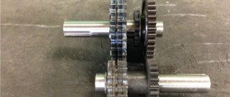
An impeller pump is a device that is equipped with a flexible working element. Models are used for pumping liquids with high viscosity. Pumps are also often used for transferring. Today, various models are actively used in the pharmaceutical, perfumery, dairy, canning and other fields.
The devices can also work with thick liquids, but in this situation much depends on the engine power. If we consider the advantages of specifically impeller modifications, then this is, first of all, a wide range of applications. It is also worth noting that pumps can be used as dispensers. They are ideal for pumping emulsions. In this case, the liquid may contain various small particles.
Pump device
An impeller pump without a motor is an impeller. It is connected to the adapter shaft. At the end there is a special head. Pump blowers are used in different types. A separate hole is provided for liquid suction. The guides in the device are installed in the main chamber. The diffuser itself is most often of the flat type. In some cases, the body is made with a jacket.
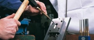
How to do it yourself?
Making an impeller pump with your own hands is quite difficult. In this case, a large chamber for pumping liquid will be required. The impeller itself must be sized to fit the outlet hole. The shaft for the standard model is available with a diameter of at least 2.5 cm. In this situation, it is more advisable to use a steel supercharger. A pipe will be required to suck in the liquid. Diffusers are mainly used flat.
They are installed above the impeller. In this case, the impeller should be located next to the blower in the pump chamber. The nominal flow of a device of this type must be maintained at 3 cubic meters. meters per hour. The motors themselves are most often installed at 15 kW. The system must withstand a pressure of 10 meters.
Model made of polystyrene foam and polyurethane foam
Before making a model of a mountain from polyurethane foam, you need to prepare the base. This could be a sheet of cardboard or a piece of plywood. Squeeze a stream of spray onto it from the bottle and form a mountain. It should be taken into account that when the polyurethane foam hardens, it expands, so the dimensions will increase. When working, do not touch uncured material with your hands!
Leave for a day to thicken. Use a sharp knife to cut off excess. The top layer can be made of papier-mâché, or simply painted in the desired colors.
You can make a mock-up of a mountain from a thick piece of polystyrene foam. Several layers of this material are pricked on top of each other, fastened with toothpicks. Then the excess is cut off and the top layer is decorated.
Your imagination will tell you how to make a model of a mountain. You can use a large number of available materials. For decoration you can use twigs, cones, artificial plants. Imitation of water can be done using a glue gun.
Pump type “NSU-3/0.35”
This impeller pump (12 volt) is equipped with a cylindrical chamber. In this case, there is a jacket to protect the body. The model has a direct adapter shaft of 2.7 cm. The supercharger is made of steel. The head of the shaft has teeth. If we talk about the parameters, then this model weighs exactly 13 kg. The nominal flow rate is at the level of 3 cubic meters. meters per hour. It is also important to mention that the feed parameter is 12 meters. The motor in this pump is of the asynchronous type, and its power is 18 kW.
Devices "NSU-3/0.75"
This impeller pump is actively used in the perfume industry. Its design is very similar to the NSU-3/0.35 modification. Pumps can handle liquids of varying viscosities. The model's camera is of a cylindrical type. The supercharger in this case is located behind the impeller. The impeller itself is used with small guides. The diameter of the adapter shaft is exactly 2.5 cm. Its head is made with teeth and is capable of withstanding heavy loads. The model has an asynchronous motor, and its power reaches 20 kW. The voltage of this NSU impeller pump can withstand 220 V at an operating frequency of 45 Hz.
Purpose of the irrigator
Some dentists actively use a professional irrigator when performing hygienic cleaning of a patient’s teeth. An equally effective and standard home appliance is stationary (with a mandatory connection to the water supply) or portable (portable).
Teeth cleaning
The attention of dentists to irrigators is drawn due to the following reasons:
- timely cleansing of the oral cavity helps prevent the development of caries and other diseases of the teeth and gums;
- there is an improvement in bad breath;
- the bracket system is properly cleaned;
- prevents bleeding gums;
- Provides care for installed implants and prevents their loss.
Doctors especially recommend using this device for pregnant women to prevent periodontitis and for patients with diabetes, who often develop gum disease when blood glucose levels increase. The device will also help children prevent the development of dental caries.
Models for dairy products
Pumps for dairy products are usually made with oblong chambers. The engines on them are often of the commutator type. The superchargers, in turn, are made of steel. Directly transition shafts are used with small diameters. Dairy products require models with a high speed setting. If we talk about power, then on average it fluctuates around 20 kW. The nominal flow rate is 4 cubic meters. meters per hour. The kinematic viscosity of a device of this type is maintained at 210 cSt.
How to build your own plane with your own superconductor and liquid nitrogen engine
Hint: keep everything small.
Introduction
Hi all. By training, I am an engineer for the operation of aircraft and aircraft engines, but in this article I will describe how I made a small electric motor using superconductors, and therefore please take my introduction as an excuse for the fact that I do not have sufficient competence and experience in the development and manufacture of electric motors , but still I did it. Therefore, dear experts, specialists, professionals and analysts, please make concessions for the amateur, and please provide all criticism and evidence of your rightness in the form of solutions made with your own hands.
Start
It so happened that in the spring of 2022 I started working as an engineer at SuperOx. I took part in the development of an electric motor based on superconductors (Photo). At first the work was interesting and sometimes dusty mixed with shavings from various materials. So many problems were solved :). Six months later, I realized that the path to a full-fledged aircraft with a superconductor engine would be long and difficult. Then the idea was born to make your own engine, put it on a small drone or radio-controlled plane and make at least one flight.
For reference. When I first learned about this company, I knew what a superconductor was, but I did not imagine that the production of such a product existed in the Russian Federation. It was really nice that such productions exist and are developing.
In the process of working and communicating with colleagues, I learned all sorts of subtleties and features of the use of superconductors. As knowledge was acquired, the engine design changed and adapted.
Somewhere in January 2022, a feeling appeared that if you don’t start doing anything, the moment might be lost forever (by the time you measure seven times, others will have been cut off long ago). At this point, I believed that I had accumulated a sufficient amount of knowledge to implement the entire project and began to work on my engine in parallel with my main work.
Initially, the idea was to develop a motor based on any available brushless electric motor for radio models, with an external permanent magnet rotor (outrunner).
An example of a brushless motor that can be found in many RC models.
But there were such obvious difficulties along the way as:
- the complexity of winding the windings on the stator. (The fact is that a superconductor wire is a metal tape with several layers of sputtering. The superconductor itself is a thin layer of ceramics. If the tape is bent too much, the superconductor layer can be damaged (
); - the stator iron (magnetic core) will be in liquid nitrogen. To cool it, an additional volume of nitrogen is required. Also, the stator iron will heat up when the electric motor is running and therefore nitrogen will evaporate more intensely;
- difficulty in removing the propeller shaft. It is necessary to provide thermal insulation between the rotor and the cryostator. It is also necessary to protect the rotor cavity from ice freezing and oxygen condensation;
- difficulty in switching windings. The conductor tape is thin and bends with some restrictions; soldering 24 contacts, trying to fit it into a small volume, should be difficult.
Diagram of an electric motor with a vertical layout and an external rotor.
It was not clear how to insulate the thermostat, how to avoid moisture freezing on the output shaft and bearings, and how to remove the propeller shaft.
Further thoughts were about the possibility of moving to brushless electric motors with an internal rotor with permanent magnets (inrunner). This idea looked more attractive. An important change is the decision to purge the rotor cavity with evaporating nitrogen. Due to this, with a constant flow of evaporating nitrogen, air along with moisture and oxygen should not penetrate inside. and therefore the bearings should not freeze. If air began to penetrate inside, the moisture from it would begin to condense on the surface of the inside of the rotor housing. The resulting ice could easily grab both the bearings and the rotor itself to the inner wall. But oxygen could be no less dangerous. The fact is that it condenses at a temperature of about -183 degrees Celsius (for comparison, nitrogen boils at -196.5 degrees Celsius). This leads to more intense evaporation of nitrogen when the energy of oxygen condensation is absorbed and cooled through a thin wall. And the very fact of the presence of liquid in the cavity where the rotor should rotate negatively affects the performance of the engine.
Diagram of a vertical electric motor with an internal rotor
This design had more advantages than the previous solution. However, the presence of a stator magnetic circuit also threatened to significantly increase labor intensity. The easiest way out of this situation is to get rid of the magnetic core. This is how the idea came to make a motor without a stator magnetic circuit (stator iron).
But the question still remained of how to increase the interaction of the magnetic flux between the stator coils and the permanent magnets of the rotor. A magnetic core is needed to transmit magnetic flux, but if the coil is brought as close as possible to the magnet (even better, the magnet is inside the coil), then perhaps this will compensate for the absence of a magnetic core.
And then the idea of a design with six distributed coils through one pole and a rotor with two poles gradually crystallized.
Plan A
In the top view it looked like this:
Diagram of an electric motor with six coils and a two-pole rotor.
Next, I started drawing the idea in 3d-cad T-Flex. By this time, it was possible to obtain several permanent magnets, the geometry of which determined the dimensions of the rotor and, as a consequence, the dimensions of the entire engine in the future.
So a design like this came about:
The first developed version of a magnetic system with superconductor coils.
I had to spend a lot of time developing the frame for the reel. The main problem was that the HTSC tape actually bends only in one plane, but allows some torsion. The combination of these two factors limits the trajectory along which this tape can be laid. But in the end, we managed to draw and print on a 3D printer the first prototype of the frame, onto which we were able to successfully attach the superconductor tape.
First printed superconductor tape winding frame
In addition to the frame, the rotor housing was also printed to accommodate the magnets, supports and the cylinder of the inner tube. Bearings and rotor axle were obtained.
To debug the engine, winding copper wire was wound onto the frames instead of HTSC tape. Each frame fit 4 turns (according to the recommendation of the person who did the engine calculations, 5 turns were needed).
Copper analog motor for checking the performance of the motor.
Everything was assembled, soldered and connected to a Castle Talon 90 ESC.
The first attempt to launch the copper analogue showed the obvious - low torque. At the initial moment, the controller begins to forcibly rotate the rotor without feedback. Once the feedback starts working, the controller can control the motor normally. But due to the absence of a magnetic circuit, feedback on the back EMF was difficult, and the low torque and moment of inertia of the rotor led to the fact that the rotor did not have time to spin up and made oscillatory turns around a certain equilibrium position.
But after the rotor was forced to spin, the engine started. And it began to rotate so wildly that I was afraid that the printed rotor would break into segments and the magnets would fly to the sides like shrapnel. Then we managed to measure 14 thousand rpm and noticed another feature: at high speeds the torque was greater than at low speeds. In the next experiment, I increased the input voltage from 12 V to 24 V and then the engine began to start on its own.
This preliminary success gave me inspiration. Believing that at high currents and speeds of the order of 10 thousand rpm, the engine power will be sufficient to rotate a propeller of small diameter and small pitch, I decided to make a horizontal engine with direct drive to the propeller.
But there was another unpleasant moment ahead. The fact is that in a vertical layout, the coils should have been in a heat-protective container (thermal mug from Ikea? :)), and in the center there should have been a thin-walled plastic cylinder. There should be a lid on top that directs the evaporating nitrogen into the cylindrical cavity of the rotor from where it is released into the atmosphere. This nitrogen gas, when released, does not allow atmospheric air to penetrate into the rotor cavity. The solution to this problem was found to be quite elegant in my opinion. A tube with holes was designed in the upper part of the vessel where the nitrogen is placed. This tube carried nitrogen vapor down along the front wall of the engine (engine with a pusher propeller) and exited in the area of the front support. Next, nitrogen gas passed through the front bearing, into the gap between the rotor and stator, and exited through the rear bearing.
Section of the engine in a vertical plane. The arrows indicate the direction of movement of nitrogen gas. (Housing insulation not shown)
The final recipe was as follows: the stator housing was a container with a central pipe to accommodate the rotor with supports. Six coils were placed around the central tube. The coils at the rear wall were switched between each other and three current leads, to which the copper wire terminals were connected. There, on the back wall, a nitrogen filler neck with a lid was attached. For the convenience of filling liquid nitrogen, the filler cap was replaced with a funnel.
The rotor consisted of an 8 mm stainless steel shaft (the shaft from a broken inkjet printer), onto which was pressed a plastic rotor housing, printed on a 3D printer, with magnets pressed into it. The propeller trunnion was attached to the end of the shaft.
The front rotor support was 3D printed from PLA plastic and a ceramic bearing was inserted into it. The rear support is also 3D printed and also with a bearing.
A set of frames with a wound superconductor and hand-turned brass current leads.
Everything was printed, glued with superglue, soldered, assembled, wrapped in cryogel, beautiful shiny tape and placed on a stand.
The engine is assembled and ready for the first freezing tests
The first launches showed the imperfection of the design. In principle, the engine began to rotate, but due to temperature deformations the bearings jammed and the rotor stopped. And given the low torque of the engine, it was not possible to start it 5 minutes after filling it with nitrogen. At some point, it seemed that the engine began to spin, but the shaft remained motionless. As it turned out, due to the low temperature, the plastic housing of the rotor shrank and, as a result, it fell apart in thin places.
Rotor housing in camber 
The rotor housing has been reprinted. After installing the rotor housing on the shaft and pressing in the magnets, the housing was covered with glass fiber on cyacrine.
Next was the struggle with the supports and bearings so that they would not jam right away (this is another half a week of research, modifications and testing). As a result, with a new rotor housing and new supports, the engine began to start stably and could provide sufficient thrust for a long time to fly an aircraft weighing approximately 3 kg (continuous operation time about 1 min).
It was decided to board the plane and fly.
At that time I had an empty glider of a Chinese Hunter aircraft with a wingspan of 1.8 m. I adapted it a little to install an engine. In particular, the rear fuselage was trimmed down to the wing attachment points in order to move the engine forward and thus make the aircraft easier to balance.
I also decided not to bother with the autopilot, but to install radio control. The final weight of the aircraft was around 3.6 kg.
I already had experience using a device of this mass, and using a conventional brushless electric motor with a rubber catapult, this plane took off and flew for a long time, and so I decided that the flight was possible (
).
I made an agreement with the pilot, went out into the field, and in the end the flight didn’t work out.
Several factors contributed to this failure:
- Large aircraft weight with low engine power. The rubber catapult accelerated the plane to its initial speed, but low engine power and a sharp climb immediately after takeoff led to a decrease in speed and, as a consequence, to the stalling and crash of the plane.
- Poor aerodynamics. The standard airframe fuselage was quite plump. Also, the protruding piece of the power frame to which the engine was attached, and two vertical planes in the rear part of the fuselage formed by the cut of the fuselage and the rear wall of the engine, do not add to the aerodynamics.
- There is another factor that could influence the operation of the engine in its own way. The fact is that the outside of the engine was covered with aluminum tape on a self-adhesive basis. And given the small distance between the rotor and the wall, alternating magnetic fields when the rotor rotates create a counter-EMF in a thin layer of foil. And with increasing speed, this effect only intensifies (demonstration of this effect using the example of oscillation of a permanent magnet over an aluminum plate).
The solutions were the following:
To reduce the weight of the aircraft, all parts were weighed, measured and a weight model of the aircraft was created. As a result, it was decided to move the engine even closer to the front of the aircraft. Remove two batteries with a total weight of 1000 g. Instead, one battery weighing approximately 300 g will be installed. To maintain balance, the battery must be moved forward by 150 mm and this required a new fuselage.
Weight model of the aircraft. Above is the old model, below is the model with a new fuselage and a new battery.
The new fuselage should also improve the aerodynamics of the aircraft.
After spending a few more days. The fuselage was designed and cut on a CNC machine. Covered with fiberglass and painted.
Manufacturing a new airframe on a CNC milling machine
Trying on the new fuselage.
Aircraft pre-assembly
The aluminum tape from the surface of the engine was removed.
In addition to the fuselage, strength frames for reinforcement and a stand for the aircraft with a new fuselage were cut out.
Airplane stand
Everything was collected and ready to fly again.
In the field, just before takeoff, an engine failure occurred. After several attempts to start the engine, I rang the motor windings and detected a break in one phase.
Sadness.
After disassembling the engine, it turned out that a crack had appeared in the inner pipe printed from plastic. As a result, the nitrogen level was much lower than necessary and the upper conductors were not cooled. As a result, when a large current is supplied, the uppermost conductor going to the current terminal burns out.
But the most important thing is that the body made of printed plastic could no longer be restored.
At this time, I did not have access to a 3D printer, but I did have a CNC milling machine. And so it was time for plan B.
Plan b"
It was decided to make the motor housing from polystyrene foam on a CNC milling machine. In the 3D-printed engine, plastic acted as a durable shell, ensuring the strength and tightness of the container, and the surface was thermally insulated with 5 mm thick cryogel.
In the new design, the outer stator housing is made of polystyrene foam. It must also provide tightness, thermal insulation and partial strength (really TRIZ). To increase the strength of the body, the outside of the penoplex was covered with fiberglass cloth and epoxy resin. A power frame made of 2 mm fiberglass was also attached to the front of the engine. There was a pipe for the rotor inside and a pipe for removing nitrogen gas at the top of the container. Both tubes are made of fiberglass and epoxy resin ETAL-Carbon Light.
Also, the filler neck was moved to the side surface, since when located on the rear wall, the filling funnel interfered with the rotation of the propeller and after filling, before launching, it had to be removed. This is not important during flights, but during development and testing it is inconvenient to constantly change the funnel to the lid and back.
Section of an engine with a foam housing
The front support had to be modified, since in the new design it was inserted from the screw side.
A cryostat with a penoplex body in the process of manufacturing.
The resulting structure was assembled and ready for testing.
This time I decided to do a preliminary test at the stand without going into the field. And during the checks the engine burned out again.
Sadness again.
The coil burned out completely.
After two days, a sea of disappointment, a liter of beer and 4 liters of selected tea, I decided to make one last attempt to create an engine on superconductors. It's time for plan B.
Plan B
Improved engine design
I still had a second set of coils wound on the frames. There were also several more frames, from which I restored a copper analogue.
Within a week, the copper analogue was restored for preliminary testing, testing and controller settings.
The HTSP engine, which I had previously assembled and tested, is designated as No. 1. It was disassembled into individual elements. The two burnt out coils were replaced. The windings were reconnected. A new design of current leads was introduced.
Stators in the manufacturing process. In order, on the left is a copper analogue, in the center are new stator coils for engine No. 2, on the right are restored coils for engine No. 1
Ready stator for motor No. 2. Slightly visible design of current leads.
For the copper analogue, the walls were cut out at the front and back so that the engine could be mounted in a similar way to a cryogenic one. Two cryogenic engines were assembled in parallel in such a way that most of the settings and tests were done on No. 1, and the final tuning and flight were performed on No. 2.
Pasting cryostats with fiberglass cloth and epoxy resin
There was one rotor for all three engines.
Ready-made stators for all motors and a single rotor for them.
I also made a simple stand for measuring thrust on a CNC machine and tested its operation on a conventional brushless electric motor.
A stand for checking the engine and testing the parameters of the electronic engine speed control controller.
After gluing and assembling, I spent two more days setting up various controllers. The Marcus SL110 controller was a pretty good fit, but after several tests it still burned out. There is a peculiarity of such controllers. When starting the engine, they can give a long series of pulses. When starting a conventional copper brushless motor, the current is limited by the resistance of the lead wires and windings, but in the case of an HTSC motor, the current is limited by the resistance of the lead wires alone. For this reason, this controller presumably burned out.
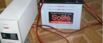
As a result of three days of settings, we managed to obtain a working circuit from a battery of lithium-polymer batteries with a voltage of 24 V and a capacity of 3.5 Ah, a Castle Fenix Edge Lite controller, and a superconductor motor No. 2.
Everything was tested on a stand with standard batteries and a radio control receiver, installed on the plane and tested again as an assembly.
Nitrogen fumes coming from under the rear engine mount.
So May has arrived.
On May 2, I took the finished plane, liquid nitrogen and other accompanying “persimmon” to the airfield. I myself am not very good at steering a radio-controlled plane, so I had to persuade local pilots. Vasily responded to my requests, although he warned that the plane might crash. But in fact, I had a much better chance of crashing the plane.
An airplane with an electric motor powered by superconductors is ready to fly.
And the first flight ended in an emergency landing.
A quick inspection showed that outwardly everything was intact and it was decided to make a second attempt, but at a lower power.
Before the second attempt, we carried out a small check of how the engine works in some modes and, after determining it, decided to take off.
This time the flight was successful.
On the wave of this success, they wanted to make another flight, but apparently the bearings began to jam again and the engine did not produce the necessary power, and at some moments it stopped. And so we decided that one flight was enough and we could end this epic.
The plane took off, made a short flight, and even if it was short-lived, nevertheless, I believe it can be considered as the first flight of an aircraft with thrust from a superconductor power plant.
What's next? The rotor design can be improved to increase torque. There is an idea on how to make supports in which the bearings will not freeze and jam. Make frameless coils to improve cooling. All this will lead to increased reliability, power and engine operating time. And after that, attach the landing gear, put an autopilot on it, to collect information about the efficiency of the engine and make several more flights... but this will be the second or next flight - the first flight has already taken place.
There will be no continuation for this project. The main task was to make at least one flight (see the beginning of the article) and this task was completed.
P.S. I would like to express my gratitude to the staff for their help, advice and support, and also for not trying to limit my creative madness. I wish you success and good funding on your long journey of introducing HTSC into everyday life. Special thanks to the city of Izhevsk for the provided glider. Also thanks for the advice on epoxy resin for liquid nitrogen.
And the main thanks to the pilot Vasily for not being afraid to take responsibility for the first flight of an aircraft with my electric motor using superconductors and liquid nitrogen.
P.P.S. 3D engine model for download: Models for download
Devices for oil and fat products
For oil and fat products, high power pumps are used. Cameras for them are used only with shirts. Moreover, the noise level in this case should not exceed 65 dB. If we talk about the design features of the models, then the impellers deserve attention. Their guides are of short length, but they can withstand heavy loads.
The impeller is installed directly in the chamber. The adapter shafts of the models differ quite significantly in diameter. Motors can most often be found asynchronous type with a power of 15 W. The pressure indicator of the devices reaches 11 meters. The nominal flow parameter, in turn, does not exceed 6 cubic meters. meters per hour.
Features of models for the production of confectionery products
For the production of confectionery products, pumps are selected with a high kinetic viscosity parameter. In this case, the pumping temperature must be at least 80 degrees. If you pay attention to the design features of the devices, you should mention the power of the engines. On average, this parameter fluctuates around 22 kW. The chambers themselves are cylindrical in shape.
Adapter shafts are used with a diameter of 2.1 cm. Superchargers are most often installed behind the diffuser. The models have serrated heads. Guides, as a rule, are found in short lengths. The nominal flow rate of the pumps is at the level of 4 cubic meters. meters per hour. In this case, the pressure parameter is no more than 13 meters. Suction pipes are used in different diameters.
Pumps for fruits and vegetables
For fruit and vegetable products, an impeller pump is required with a large suction pipe. Devices must operate at a temperature of at least 70 degrees. The engines on the models are usually of the commutator type with a power of 15 kW. They operate from a network with a voltage of 220 V and an operating frequency of 55 Hz.
They use short transition shafts. Thus, the nominal flow rate of the devices is insignificant. However, the pressure parameter is on average 12 meters. It is also important to note that the impellers are installed directly in the chamber. Today, there are many modifications with shirts on the market. Their average noise level is 60 dB.
Story
Da Vinci helicopter drawing.
1480s. The idea of a propeller comes from the Archimedean propeller.
There is a well-known drawing by Leonardo Da Vinci depicting a prototype of a helicopter with a main rotor. The screw still looks like Archimedes.
Aerodrome machine of M. V. Lomonosov. Model.
In July 1754, Mikhail Lomonosov demonstrated an aerodrome model. The blades on it are already flattened, which brings them closer to their modern appearance. It is assumed that Lomonosov used the image of a Chinese children's toy - a bamboo helicopter.
The modern Japanese toy taketombo is a bamboo helicopter, derived from the Chinese version. On the left is bamboo, on the right is plastic.
Pumps in the cosmetic field
The impeller pump for making ointments is compact. A powerful engine is not required in this case. Adapter shafts for models are installed with a small diameter. Superchargers are most often used in steel. The impellers themselves are mostly flat. Impellers in pumps are used with guides. If we talk about device parameters, it is important to mention the power, which in some models does not even reach 12 kW. The pressure indicator, in turn, is no more than 8 meters.
Tips and tricks for using an irrigator
To clean the oral cavity efficiently and effectively, it is recommended to follow the following rules:
- Beginners should use a device that regulates the lowest power flow of water. This is necessary to prevent bleeding gums and other problems with teeth that are not yet accustomed to this cleaning method.
- Dentists' recommendations are based on dividing the oral cavity into 4 sections. Start cleaning with the front teeth.
- All areas of the oral cavity should be cleaned - the outer side of the teeth, the inner side, the gums, interdental spaces and periodontal pockets, in which food often settles, leading to the development of gum disease.
- All movements should be smooth, since a sharp impact can lead to an inflammatory reaction of the gums.
Making your own irrigator significantly saves the family budget, and also makes dental care more thorough and of higher quality.
Models for perfume production
For the production of perfumes, an impeller pump is usually used with low power. In this case, the motors must be of the commutator type. They operate from a mains voltage of 220 V, and their operating frequency is 53 Hz. The adapter shafts themselves are used with a diameter of about 2.5 cm. The models differ quite significantly in the size of the suction pipes. In this situation, a lot depends on the volume of the main camera. Superchargers are often made of steel. Only flat guides are suitable for such devices.
The diffuser in many models is located near the wheel. If we talk about pump parameters, it is important to mention the nominal flow. On average, this figure does not exceed 3 cubic meters. meters per hour. However, there are also more powerful models. In this case, the pressure parameter lies within 12 meters. The maximum pumping temperature allowed is 70 degrees. Kinetic viscosity must be at least 230 cSt.
What is an irrigator
Irrigator with nozzles
An irrigator is a device used for oral hygiene to cleanse teeth and prevent the development of gum disease. The principle of operation of the device is to supply a powerful jet of water, which, under its pressure, is able to clean the interdental spaces from food debris and remove plaque from the surface of the teeth.
The device consists of three main parts:
- mechanical part;
- container for water if the device is portable (portable);
- nozzles for water supply.
The container is often filled with not just plain water, but a special solution that allows for proper dental care. Solutions can be different:
- antiseptic;
- hygienic;
- medicinal;
- designed to improve bad breath.
Flow irrigator
Pumps in pharmaceuticals
For pharmaceuticals, the shape of the impeller is very important. In this case, the guides must be at least 1.2 cm thick. All this will allow you to pump liquid with small particles without any problems. The kinematic viscosity parameter should be around 210 cSt. At the same time, the nominal feed is recommended to be at least 4 cubic meters. meters per hour. Additionally, the pressure indicator is taken into account. On average it is 12 meters. However, if we consider modifications with 10 kW commutator motors, then in this situation for pumps this parameter will reach up to 14 meters.
Educational mini-attraction
You can talk about the basics of one of the most interesting sciences - physics - using a fountain model made from a plastic bottle and a balloon.
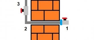
In addition to the ball and bottle, you need to prepare a sharp knife with a thin blade, a straw for cocktails (the longer the better), a piece of plasticine, window putty or a large ball of chewing gum, blue food paint and a spacious basin. You can conduct an experiment in the bathroom so as not to cause a “flood” in the apartment.
So, let's begin. We make a small hole in the side of the container the same diameter as the tube. Carefully seal the junction of the parts and pour in colored water.
We install the structure in a basin or in a bathtub. We inflate the balloon and put it on the bottle. When air from the ball begins to flow into the tank, it will squeeze out water, that is, our fountain will start working.
Pumps for the production of household chemicals
An impeller pump with commutator motors is excellent for the production of household chemicals. The limiting frequency in this case should not exceed 50 Hz. If we talk about the design features of the models, it is important to note that transition shafts are allowed with a diameter of at least 2.6 m. This ensures good pressure. The supercharger also deserves attention. In these configurations it is installed behind the diffuser.
The impellers themselves may differ in diameter. On average, the nominal flow rate is 4 cubic meters. meters per hour. The engines in this case have a power of at least 12 kW. For liquid, the maximum temperature allowed is 75 degrees. Many models are made by manufacturers with shirts.
Details of a homemade water ionizer
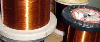
The creator of a water ionizer will need two plastic containers with a capacity of 5 liters each. Two such containers actually provide separate chambers for the working electrodes.
Titanium electrodes are, of course, the best option for this case. However, aluminum or copper electrodes are often used by water ionizer manufacturers.
Accordingly, this option is also suitable for a homemade design. You will also need:
- PVC pipe with a diameter of 50 mm,
- a small piece of suede,
- several alligator clips,
- electric wire,
- power system 12 (24) volts,
- two copper (titanium or aluminum) electrodes.
Models for working with petroleum products
A wide variety of pumps can be found for pumping petroleum products. First of all, it is important to mention compact models whose power does not exceed 10 kW. In this case, transition shafts are installed with a diameter of less than 2.2 cm. The chambers themselves are short. Shirts for them are installed quite rarely.
On average, the nominal flow of devices is 4.5 cubic meters. meters per hour. The pressure indicator does not exceed 11 meters. The guides for these pumps are short. Thus, the limit frequency parameter can reach 60 Hz.