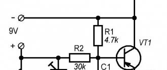
Today it is quite difficult to imagine your life without the Internet. Every day people use it to communicate with friends, study or work. Not everyone has access to a stable network connection. Therefore, some people have to boost the signal using an antenna to make the Internet work better. This device can be purchased at a specialized store or made independently. It is worth noting that a DIY antenna created for the Internet is in no way inferior to a purchased one.
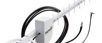
Modem antenna - the best device for signal amplification
Is it possible to make an antenna for 3G and 4G yourself?
Some people think that it is impossible to make an Internet amplifier at home. Such people believe that for this you need to be well versed in physics and radio engineering.
In fact, even a person with scant technical knowledge and without special practical skills can make an antenna on their own to improve network reception. However, despite this, you will still have to familiarize yourself in advance with the step-by-step instructions for making such receivers and the features of their operation.
Principle of operation
With the advent of GPS devices for determining location, fewer and fewer people know how to use a compass. The first component of a GPS navigator is its antenna. It is with the help of it that the signal is received from the nearest navigation communication satellite. The accuracy and ability to receive the desired signal depends on the correct selection of the characteristics of the receiving device (antenna).
Incorrectly selected characteristics of the receiving element can greatly complicate life during natural phenomena such as snow or rain, making location determination impossible just at the moment when it is most needed. Therefore, special design organizations are involved in the design of GPS antennas, and without mandatory field tests, the product is not put into industrial production.
Additional Information . GPS – Global Positioning System. Translated, it means global positioning system. It was originally developed by the military for their needs in North America. It has proven itself so well that military departments at the end of the last century were forced to share the technology with the civilian population.
Today, any new gadget has a built-in GPS antenna. However, the accuracy of location determination often leaves much to be desired. There are three main reasons for the device to malfunction:
- The absence of a satellite at a given specific moment in a given specific area;
- Poor quality of the antenna device;
- Slow software.
What is a homemade receiver?
An antenna is a special device that can be used to greatly enhance the signal reception level on the modem. Depending on the installation method, they can be divided into two main categories:
- Rooms. Compact device for indoor use. It is equipped with a powerful amplifier to receive even the weakest signal.
- Street. Most often they are placed on the roof of the house. The size is several times larger than indoor ones.
Important! You can make both indoor and outdoor receivers yourself. The main thing is to have a diagram of the device.
Connecting gadgets
Modern gadgets have a built-in GPS antenna. However, they cannot always be used as navigators. Not in all unfavorable conditions they can pick up a signal from the nearest communication satellite. Such unfavorable conditions include:
- Car windows with a coating that interferes with the free passage of signals;
- The size of the gadget screen does not always allow you to clearly see all the details of the route;
- The overall dimensions of the tablets do not allow it to be placed under the windshield of a car.
When going to a store to purchase the necessary device, it is necessary to explain in great detail to the sales consultant the type of gadget for which the antenna is being purchased, for what purposes the device is planned to be used, as well as what result of use is required, where it will need to be installed.
All this must be taken into account because today's amplifiers use such modern means of communication as a USB port and Bluetooth. For use in gadgets, the latest encrypted data transfer protocol is preferable, because does not imply the need for additional wires that interfere with its use, for example, with a smartphone. However, with this connection it is necessary to very accurately install the antenna in the required location. Computers usually use special USB connectors.
GPS in the car
A modern car requires a navigator built into the on-board computer. Navigation is very convenient for any driver to use.
Car navigator
Designers involved in the design of car navigation systems settled on the following operating algorithm:
- An external type device receives and amplifies the signal coming from the satellite. In an enhanced form, it ends up in the navigator;
- The received signal appears in the navigation receiver. Based on this, the location of the vehicle is determined. Next, the coordinates are clarified using the system control unit;
- After specifying the coordinates of the vehicle's location, the optimal route to the final destination is calculated. This happens on the basis of road maps loaded during the production of the machine. The navigation system is often controlled by voice. If it is necessary to update maps loaded into the car’s memory, use special boot DVDs;
- The correct direction of movement is determined using the parameters of the angular velocity of the wheels, which is calculated by the on-board computer.
When setting up a vehicle location on a map loaded into its memory, the vehicle must be at static rest and in the location indicated on the map. In this case, the GPS antenna for the navigation unit is installed at the factory.
Homemade receiver options
Before making a means to improve the signal, you need to familiarize yourself with the types of homemade questionnaires.
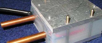
With copper winding
Copper wire - often used when creating homemade receivers.
This is a budget option, which is the easiest to make yourself from improvised means. The device must be equipped with a long reflector, since the quality of signal reception depends on it.
Another important detail that should not be forgotten is copper wire. It is wound over the mast. It is recommended to use wire with a diameter of 2-3 millimeters.
From wire
This option also uses copper wire. It is bent at an angle of 45 degrees to end up with a diamond-shaped design. It is then attached to a wooden or metal frame and connected to an amplifier. Such a design is capable of picking up a signal at a distance of 20-30 km from the tower.
Modification without feeder
Most purchased antennas for the Internet and television are equipped with a special feeder. However, it is not necessary to use it. Devices that are not equipped with it operate at a frequency of 300 Hz.
Modifications without a feeder must be made with copper or aluminum winding. It is placed on a mast with a diameter of 23-25 mm.
Double core
Reflectors - help to strengthen the signal.
This model is most often used for installation outdoors. Its operating frequency is about 400 Hz. It differs from other modifications by the presence of a diamond vibrator. The design also contains several metal gratings 30-40 cm long.
Important! To make the signal better and more stable, reflectors must be installed in models with a double core.
Vertically polarized and braided
If configured correctly, such a panel antenna will be able to output 300 Hz. As in the previous version, special vibrators and metal grids are used here, which help improve signal reception. An aluminum winding is installed on the mast.
There are also side racks that are tilted at 45 degrees.
Vertical polarization without braid
This modification is suitable for modems that operate at a frequency of no more than 200 Hz. The structure consists of side metal posts and an aluminum plate. It is customary to connect it to the modem with a special two-wire cable.
Antenna Kharchenko
This is a universal device that is capable of operating in the frequency range from 450 to 900 MHz. The structure is made of copper wire with a diameter of 4 mm. It must be bent in such a way that the result is a figure eight. It is attached to an aluminum plate. The device is connected to the modem with a cable that can withstand a resistance of 50 ohms.
Log-periodic
Kharchenko's modification is the most popular homemade antenna.
This device is considered a high-frequency receiver. It receives a signal in only one direction, but at the same time picks up a wide range of frequencies.
The design consists of several metal tubes that are located parallel to each other. The longest tubes are located at the base. The shortest ones are on the edge.
Features of antenna placement in smartphones
Don’t forget that every mobile phone contains not only antennas for cellular communications, Wi-Fi, GPS, but also additional antennas for compatibility with older communication standards 4G, 3G, etc.
It is necessary to precisely coordinate all antenna devices with each other, because mutual influence and crosstalk continue to do their dirty work and have a negative impact on the system as a whole.
The optimal location of the antennas in the phone, as well as relative to each other, will be of key importance and will affect their performance. A change in position of a few millimeters will affect the quality and stability of the connection of a working device. Typically, during the test phase, adjustments are made to the antenna placement to ensure optimal performance.
Due to the requirements for increased throughput, MIMO and Beamforming technologies are used. The small size of the antenna operating at frequencies above 28 GHz increases the potential of the technology stack used. Due to this, the gain increases.
For high-frequency antennas, the design is not so closely related to the overall structure of the phone. However, big problems arise when integrating the antenna into the device behind the metal cover. In these realities, it is no longer an imperceptible obstacle to the propagation of the wave, but has a fairly strong influence on the characteristics. And here the methods used to design fairings in the space industry have found application. The cover is designed in such a way that it forms a lens in a certain place, which improves the radiation pattern as well as scanning characteristics. However, this problem is not so serious when placed behind a glass or plastic cover.
Another approach that also takes advantage of the small size of the antenna is to integrate the structures into the metal circuit of the phone. This is clearly demonstrated in the figure below.
Don't forget about safety, especially for a device that a person wears approximately 80% of the time in close proximity to the body.
At frequencies below 6 GHz, existing SAR (Structure–activity relationship) standards are used to assess the effects of electromagnetic radiation. At millimeter wave frequencies, the electromagnetic field almost does not penetrate the body. Most of the radiation is reflected, and what gets in is completely scattered within 3 millimeters of the surface, so SAR is not a serious threat to the body:
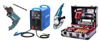
DIY making
Before you make your own antenna for mobile Internet, you need to figure out how to do it correctly.
Device and optimal dimensions
Many people believe that the dimensions of the antenna do not affect anything, but this is far from the case. In fact, the level of signal amplification largely depends on the size. Therefore, the device should be made larger. Recommended width and length are about 30 cm.
Important! If you need a compact antenna, you can use Kharchenko’s biquadratic drawing. It is ideal for receiving mobile Internet for your phone.
Vibrator requirements
It is recommended to make it from large copper or aluminum. An ordinary solid rod or tube is used as the body of the vibrator. If you don’t have copper or aluminum at hand, you can make a device from the “whiskers” from a Polish antenna.
The diameter must be at least 4 mm. In this case, it will be possible to achieve a stable signal without interruptions.
Cable selection
The connection cable should not be too thick.
Particular attention should be paid to the cable that will connect the antenna. It is recommended to use cables with low resistance, about 55 ohms. They do not emit interference and do not degrade signal quality. The wires used must be equipped with an F female-CRC9 connector.
Specifics of the reflector design
The reflector is a panel whose surface is covered with foil. The basic requirements for reflectors are as follows:
- they should be slightly larger than the antenna;
- distance to the vibrator - at least 30 mm;
- the structure is slightly bent near the central part.
Important! Reflectors should only be made from metal.
Adapters
An antenna adapter is used when replacing a car radio with a product of a different brand. The device allows you to reduce the difference in settings and design solutions, and also enhances the quality of searching for radio frequencies.
According to experts, purchasing an adapter is necessary:
- when the sound quality decreases, there is interference, noise, distortion in the played video and audio recordings;
- when the number of received radio stations decreases;
- when the signal in the device periodically disappears;
- when the picture on the screen of the radio or video playback device is blurry.
When selecting an adapter for a machine, you must consider:
- uniform amplitude-frequency indicators of the adapter;
- the presence of a gain of about 15-25 dB;
- sufficient height of dynamic range;
- presence of low noise figure and high gain.
The designs and dimensions of adapters for passenger cars and trucks may differ.
Creation process and verification
The antenna manufacturing process consists of several sequential steps:
- Determine the perimeter of the antenna square. For a regular 4G modem this is 140-145 mm.
- Creation of the "eight". It is better to make it from copper rods. The length of each side of the created structure should not be less than 30 mm.
- Connecting the cable. It is soldered to the ends of the antenna. A USB connector for the modem is attached to the second end of the cable.
- Installation of a reflector with a vibrator. They are placed in .
The assembled structure must be attached to the rack. Its height depends on where the receiver will be installed.
Additional Information! To check that the assembled device really works, it is connected to the modem. If the signal improves, then everything was done correctly.
Connection and signal transmission options
USB connector - often used when connecting an antenna to a modem
After creating a receiver, some people encounter difficulties connecting it. The devices must be connected using connectors that are suitable for the modem. USB is most often used, as it is the most popular modern connector.
Send data wirelessly
Instead of connecting the receiver to the modem with a cable, you can transfer data wirelessly. To do this, two electrodes 40-50 mm long are connected to the device. After they are soldered to the structure, they are moved apart. After this, you can check whether the wireless Internet will work on your tablet or smartphone.
Classification
GPS antennas for car radios are divided into:
- external;
- internal.
External devices are designed to search for radio and television signals. The device is highly sensitive and is mounted on the outside of the machine. It is necessary to take into account the exposure of the device to precipitation and changes in temperature conditions. The equipment is equipped with an adapter that increases the search parameters for radio frequencies. External devices are attached to the body, trunk, roof, bumper or fenders of the car.
In-cabin devices are mounted on the windshield of a car. The equipment is equipped with amplifiers inside the housing. The device is universal, suitable for different types of car radios, does not require complex installation work, but is very expensive.
An active GPS antenna is a standard device, the system of which is supplemented by an internal signal amplifier. The devices are sensitive, accurately and quickly detect a large number of radio and television waves. The device reduces the amount of interference and noise when playing music and videos.
The functionality of a passive type device depends on the volume of electromagnetic radiation in the area. If there is a small amount of interference, the reception of the radio signal will be stable, but if there are electrical appliances within the range (in cities), the reception accuracy will decrease.
By type of design, devices are divided into:
- asymmetrical;
- dipole.
A device with an asymmetrical housing is mounted perpendicular to the plane of radio frequency propagation. The equipment is equipped with a telescopic structure, consisting of parts that are unfolded manually or using an electric drive. The antenna includes a pin equipped with a spiral at the base.
Dipole devices are equipped with 2 rods located symmetrically. The devices are mounted in a horizontal position. The type of equipment is optimal for placement inside the car.
How to connect an external antenna to your device
Antenna for car radio
When purchasing an external GPS antenna, you must clearly explain to the seller what device you are buying it for; this must be done, since modern signal amplifiers can be used using a USB port, as well as Bluetoot, namely, you can connect it yourself:
- A signal amplifier with a Bluetooth connection is ideal for a smartphone; all parameters will be transmitted using a special protocol, you do not need additional connectors;
- PCs and laptops now have a USB/PS2 connector installed, so you can choose an external amplifier to connect through it;
- Some tablets do not have a USB input, then the solution is to connect via Bluetoot; the effectiveness of this antenna is achieved by an autonomous power supply and the need to correctly install the antenna mount.
Types of connecting an amplifier to a signal receiver
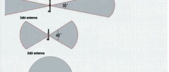
Half-wave vibrators
The Internet has gone around the video: instead of an antenna, a smartphone receives a piece of bare wire soldered to a connector. It's amazing - the radio is picked up! Nothing surprising. In radio broadcasting, vertical linear polarization is used; a wire of any length can amplify the signal. Radio engineering textbooks show that you can achieve higher results if the size is a multiple of a quarter wave:
- Equal to the wavelength.
- Half wavelength.
- Quarter wavelength.
There are other options, some radio amateurs claim: the best reception is obtained with a receiving antenna length of 5/8 wavelength. We won’t dwell on this today. Each of the above devices is characterized by internal resistance, the value is, if possible, equal to the impedance of the cable or receiving device:
- Hertz vibrator – 300 Ohm.
- Half-wave vibrator – 73.5 Ohm.
- Quarter wave - 37 Ohms.
In accordance with the above, half a dozen standard cable ratings have been identified, most often we will see RK - 75, RK - 50. The latter has the greatest circulation between communication equipment
It is important to use coax that is suitable for the type of devices you are using. On old TVs, the inputs are specially marked in Ohm
VHF uses RK-50 cable. Consequently, losses caused by reflection of the line signal are minimal.
The Internet has been circulated by a half-wave dipole circuit with a length of 75 cm on each side. The receiving device serves the VHF (FM) band, which can accommodate many radio stations. Let's make it clear:
- the length of the vibrator is half the wavelength;
- each arm of the vibrator is equal to a quarter of the wavelength.
In total we get: the device is tuned to a broadcast frequency of 100 MHz, a quarter of the wavelength will be 75 cm. The radiation resistance of the structure is 73.5 Ohms, so the antenna for the radio receiver is made with your own hands from a piece of RK-75 cable:
- To form one arm of the dipole, remove the external insulation over a 75 cm long section. Leave the screen braid intact.
- Then we turn the copper mesh inside out with a stocking, pulling it down and straightening it by 75 cm. The second arm of the dipole is formed. If it is difficult to stretch the screen over the insulation, take a piece of copper tube 75 cm long and stretch it. The braid is cut off, replenishing the contents of the trash can.
- The copper tube is carefully soldered to the screen, and the device is ready. There is no need to match the cable, both have a resistance of 75 Ohms. A modern receiver may have a completely different impedance. Read more in the technical specifications listed in the passport.
- Installation is carried out on the mast. Higher is better, but! A passive antenna for a radio station, made with your own hands from a piece of cable, greatly reduces the signal level. We will consider later how to solder a range amplifier, equip it with an impenetrable housing, and hang it near the antenna. A practical topic for a course project of an average degree of preparedness for a radio engineering university student. Today the question is postponed.
Recommendations
If we talk about recommendations for the creation and use of such antennas, then first of all we should note several.
- There should not be any metallic foreign objects near such a device. Otherwise, they may interfere with the reception of the signal or reflect it, which will also negatively affect the quality of its reception.
- Care should be taken to protect the antenna from exposure to natural factors. Otherwise, its parts may rust and sooner or later the device will simply fail.
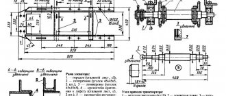
- In most cases, it is necessary to make drawings before starting work, where you need to describe in detail the dimensions and dimensions of the device, its type, as well as the algorithm of actions for its creation. This will make it possible to quickly and accurately implement one or another idea and obtain a high-quality antenna for receiving a stable FM signal.
How to make a radio antenna with your own hands in 15 minutes, see below.
P O P U L A R N O E:
No one would like to use any device that would have to be charged frequently. In portable devices, battery life is an important parameter, so it is useful to add another function to various ways to reduce power consumption - automatic power off, which will help save battery power if the user forgets to turn off the device.
Second application – blower housing
Having scoured the Internet, I found several options for using a keg as a body - a drum, a speaker with an amplifier, a miniature stove, a barbecue, a lamp.
I will also offer my own options - a housing for a charger and a housing for a small compressor, or rather a blower.
True, the charger can be placed by choosing a more convenient case. But a small blower - well, it’s just more convenient!
Third application – a vacuum receiver in a device for changing oil in a car engine
The manufacturer claims that the excess pressure in its keg is approximately 1.5 atmospheres, so using a tin can for more serious pressure risks an explosion. But it is possible to use the keg as a vacuum receiver.
an oil pump out of it - a device for changing oil in a car engine, as well as in other units, through a hole for the oil dipstick or oil filler plugs.