Now the time has come to talk about what was inside my box, cut out of plywood with a jigsaw. At the heart of everything was a circuit diagram on the controller, powered by 2 Krona batteries (9+9 V). I recorded the music on a 16-32 MB SD card. Moreover, the box played a new melody every time it was opened. Let's start in order!
Elemental base of the contents of the box
The core of the circuit is the Atmega16 40-pin microcontroller, which controls the playback of melodies. The case has a DIP so that it can be easily inserted and removed from the socket located on the board. The Atmega16 picture is as follows:
Another equally important chip is the LM4860M 1 W, 16-pin audio amplifier, from the outputs of which the amplified signal goes to an 8-Ohm speaker. I took the version of this microcircuit in the SO16 package.
You will also need 2 microcircuits - voltage converters: 7805 in the TO-220 package, the output of which is a constant voltage of +5 V, and IRU1117-33 in the SOT-223 package, with a constant output voltage of +3.3 V, from which the SD- map. An image of these chips is below:
To run the controller you need a 16 MHz crystal oscillator. SD card 16-32 MB, now such a small flash card is difficult to get, but previously they came with some camera models in the kit. All resistors and capacitors are in SMD design for surface mounting.
Circuit diagram of a music box
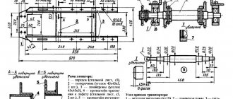
The electrical circuit of the box looks like this:
As you can see, out of 40 pins of the microcontroller, only 18 are used. Pins 5 to 8 – exchange with an SD card, 9th – for resetting the controller, 10 – +5V power supply, 11.31 – ground, 33-40 – via a divider to an audio amplifier. The Atmega16 microcontroller needs to be flashed, but not on the board itself, but on a special device connected to the computer via RS-232. Exchange with the computer occurs through the SPI interface of the controller (pins 5-8). The firmware is downloaded using the PonyProg computer program. The firmware itself (Music_box_16.hex) and a screenshot of the installed fuses in PonyProg (PonyProg_Mega16_Fuses.bmp) are in the attached archive. You will also find technical descriptions (datasheets) for the chips and microcontroller used.
PCB diagram
I laid out the tracks on the printed circuit board in the Sprint Layout4 program. Accordingly, the file shkatulka.lay is in the archive. A board measuring 130x70 mm is made of one-sided foil getinax. All SMD resistors and capacitors, LM4860M chip, IRU1117-33 are placed on the side of the tracks, and the microcontroller, SD card slot, electrolytic capacitors, 7805 chip are placed on the other. The PCB drawing is shown below:
To etch the board I used the old “iron method” and ferric chloride. Then I soldered all the elements, leaving the speaker, power button and power from two 9 V batteries outside the board. Unfortunately, at that time I did not have a camera at hand, and this was not my goal (to capture my work), so I have no opportunity to show the installation I received, and I will not disassemble the non-removable box. Then I left myself the opportunity to only change the batteries and rewrite the flash drive.
Recording melodies for the box
The SD card needs to be formatted to FAT16. The tunes you want to be played by the box should be prepared. The total number of melodies is up to 100. Playing time is 1 minute. Audio format – .wav PCM 16 kHz 8 bit mono. Name the files – “ring_00.wav”, “ring_01.wav”, etc.
Archive.7z for download:
Stuffing for the box
(5.8 MiB, 281 hits)
OK it's all over Now! Collect, launch and enjoy!
PS
Don't forget to subscribe to the newsletter (-> on the right sidebar)!
In the music box, almost at the very bottom, moments of long-gone days are quietly sleeping. The once popular accessory is now gathering dust in museums or on mezzanines filled with all sorts of rubbish. It might have continued to be this way if the designers had not decided to revive the music box, making it a real luxury item. We'll talk about the brightest examples in our review.
Starting from November, all the country's screens are filled with a cheerful Santa Claus with a bottle of Coca-Cola in his hands. From year to year, advertising practically does not change, so the main character becomes almost family, and in the supermarket the hand itself reaches for the fizzy drink. Now it has migrated to the lid of the music box. This Santa Claus, of course, won’t bring Coca-Cola, but he will delight you with music.
The main thing is a roof over your head. As it turned out, this truth is relevant not only for people, but also for music boxes.
This music box is made to order. The designer not only chooses the melody the client likes, but also creates portrait figures of the birthday person or members of the client’s family.
Music box in the form of a medallion, stylized in antique style. Designers claim that with one such gift you can win a girl’s heart.
If the capricious charmer remains indifferent to the singing heart, you can try giving her a music box in the form of a carousel. Just first you should ask: does the girl like music or is the best gift for her in the jewelry department?
What progress has come! Manufacturers have come up with a music box for the iPad. To activate it, you need to download a special application to your iPad, and you can enjoy the melodies.
A music box created specifically for the anniversary of the Beatles. However, the lid of the product speaks volumes about this. As for the repertoire of the box, it consists exclusively of songs of the legendary group.
Children will definitely like this box. The designers periodically change the main characters of the box. One thing remains unchanged - the nature of the product.
A music box for those who write music. Create melodies, record them on a special card and enjoy the results.
Designers suggest creating such a box with songs yourself: paint it in your favorite color, add all kinds of figures, inscriptions and give it to a loved one. After all, the best gifts, as you know, are made with your own hands. If you can’t make a music box yourself, you can give it to the birthday boy. We are sure that anyone will like such a gift.
If you hold the musical mechanism in your fist, its sounds will be barely audible. Only if you attach it to a board that serves as a resonator, will it fill the room with melodic ringing. Place it in a beautiful box, and its lucky owner will enjoy a serenade every time she opens the maple lid.
From the accessories, in addition to the musical mechanism, you only need a pair of brass hinges with an opening limiter that holds the lid vertically while the music is playing.
- Overall dimensions: width - 229 mm; depth - 165 mm; height - 73 mm.
- Dowels strengthen connections and create contrasting accents.
- Open the lid to hear the melody and see the brass mechanism in a compartment with a transparent window.
- The musical mechanisms sound different, and you can choose one with the melody you like.
Create the body of the box
1. From a 19 mm board, cut a blank 67 × 254 mm for the front wall A
and two blanks 67x178 mm for the side
walls B.
2. Using a straight 12mm router bit set into a router table, create a rebate at the rear end of each side wall B (Figure 1).
3. Move the router table fence to create a 10mm rebate for the cover on the inside of front A
and side
walls
B (Fig. 1, 2).
Please note that the side walls must be mirror copies of each other.
4. File the bevels at the ends of the front wall A
, giving it a final length of 229 mm
(Fig. 1).
Then make bevels at the front end of each side wall
B
so that their length is 165 mm.
5. File the back wall C
in width, taking into account the distance from the lower edge of side wall
B
to the edge of the fold for the lid
(Fig. 1, 2).
To determine the length of the back wall, dry connect (without glue) the front
A
and side
B
, securing them with masking tape. Adjust the length of the back wall to the distance between the folds of the side walls.
6. Using a straight 6mm router bit set into a router table, cut into the front, back and side walls A, B, C
tongue 6x5 mm for inserting bottom
D (Fig. 1
and
2).
Music box on PIC16F753
At one time I was very impressed by this post about creating a light and music device on a microcontroller as a gift for my beloved. And one day my time came to give such a gift. Considering the differences from the author of the mentioned project in skills and tools; Being very limited in preparation time (3-4 days), I went a different route and developed my own musical device for installation in a box purchased in a gift shop. It is distinguished by a simpler design and ease of manufacture. The article describes the details of my project and their motivation. Be careful, photos (only about 1MB).
Scheme
As you can see, there are very few details.
Power supply in the range of +3..+4.8V from three AAA batteries is suitable without the use of stabilizers for both the D1 microcontroller (PIC16F753) and the DA1 amplifier (TDA7052A). This amplifier chip is unique in its kind, because among its analogues it requires a minimum number of external elements. The use of a power amplifier is necessary: if you try to connect the microcontroller output directly to the speaker, you will not be able to get sufficient volume. To operate the amplifier, a capacitor C1 with a capacity of 220 μF is required. It is impossible without a capacitor: if the internal resistance of the power source is not low enough, then the sound will be quiet and with strong distortion. A capacitor C4 is also needed to isolate the audio signal to DC. Trimmer resistor R2 adjusts the volume. R1 limits the adjustment range. Together with capacitor C3, it also forms a low-pass filter. In principle, C3 can be omitted. At first I wanted to do this, but then it seemed to me that to reduce sound distortion it would be better to remove ultrasonic frequencies from it by installing C3.
The TDA7052A (unlike the TDA7052) has a separate volume control input by applying the appropriate voltage to it (not shown in the diagram). But trying to use it does not simplify the circuit at all and does not improve its operation. Fortunately, leaving this input unconnected does not interfere with the normal operation of the amplifier.
A few words about choosing a microcontroller. The most important criterion is the supply voltage range. When the battery is almost discharged, the voltage on it drops to 3V (1V per cell). In a fresh state, the voltage can rise to +4.8V or even more. Unfortunately, more modern 16-bit microcontrollers, which have high speed and a lot of memory, usually require power in the +2.7..+3.6V range. To lower the voltage, it would be necessary to use a stabilizer, and not just any one, but with a low voltage drop (Low Drop-out), taking into account the voltage on the battery at the end of its service life. I decided to keep it simple. Of the Microchip controllers (I have the most experience with them and have a programmer), therefore, only 8-bit ones are suitable. It would also be possible to use 16-bit ones from the PIC24F series. I'll probably do that with my next music box. Still, the PIC16F753 is very cramped both in terms of speed and memory capacity. But it has a built-in 9-bit DAC, which is very suitable for sound synthesis.
For simplicity and reliability, I also decided not to use any power management or energy saving schemes. A simple switch (not shown in the diagram) breaks the battery circuit, and that's it.
Assembly
We buy a suitable size and type of box. I found this one. Unfortunately, there was no rectangular box; it would have been easier to work with.
I didn't make the printed circuit board. There are no conditions for this at home, and ordering from a factory is too time-consuming and expensive. Therefore, I assembled the circuit on a breadboard. I managed to cut a piece of the board to the size of the box with a jigsaw. The dimensions and shape predetermined the layout of the parts. Here is a photo at intermediate stages of assembly:
The programmer is connected with wires while writing and debugging the firmware. I installed the microcircuits on sockets, and for good reason: of the two amplifier microcircuits purchased at the radio market, one turned out to be broken. We managed to avoid resoldering it.
View from the back of the board.
As you can see, long or intersecting connections are made with MGTF wire, and short ones are made with cut legs from capacitors and resistors. After checking the functionality of the circuit using test firmware, you can begin developing and debugging the main program. Read more about it below. After the firmware is fully debugged, turn off the programmer, resolder the speaker and turn on the switch. Last check.
After this, you need to mount everything in a box and cover the top with cardboard for aesthetics. We cut out and bend such a design from black cardboard in the shape of a box.
Use a knife to cut a hole for the switch. An awl is used to poke holes above the speaker. Next, glue the switch to the cardboard and the speaker to the regular place on the board:
Final view of the open box:
PIC program and music preparation
Sound synthesis
Having a 9-bit DAC, in principle, you can get a fairly complex audio signal, but in the case of the PIC16F753, the possibilities are limited due to the small size of the microcontroller program memory - only 2048 words.
As a rule of thumb, even a simple player program written in assembly language and optimized for code size takes about 1000 words, leaving very little for notes. And there is absolutely nothing left to store samples when using a sound synthesis method like Wavetable. The use of such powerful methods as FM synthesis is hampered by the insufficient speed of the processor and the lack of a hardware multiplier. Therefore, all that remains is the synthesis of rectangles - symmetrical or with variable duty cycle. The second option gives some variety of timbres - see, for example, the collection “This is Tritone 2” (also available on Youtube). I implemented this method in the box. It was possible to implement polyphonic sound: 4 independent sound channels. You can control the volume of each channel. We find the frequency corresponding to the desired note using the uniform temperament formula: f = 440*2^(n/12), where n is the note number in semitones, n=0 corresponds to “A” of the first octave. Since we have 4 channels, we need to simultaneously generate 4 signals and sum them before output. The most common solution is to use a common sampling rate for all channels. In this case, the processor calculates the output sample for each channel at regular intervals. The resulting values are summed up and fed to the DAC.
The desired periods of square wave signals are, in general, not a multiple of the sampling period. Let's say for the note “A” of the second octave we have n=12, f=880 Hz. With a sampling frequency Fs=27777.8Hz, each signal period should last ~31.57 output samples, which is unrealizable. There are three options here:
- Round the period to an integer number of samples. In this case, the resulting period will differ from the specified one, i.e. the music will be out of tune.
- Vary the duration of the period within plus or minus one sample so that the average period of the received signal is equal to 1/f. From a signal processing theory perspective, this is equivalent to nearest neighbor interpolation. As a result, significant non-harmonic distortions occur in the sound, and peaks appear in the spectrum at extraneous frequencies. To the ear, the signal simply becomes “dirty”.
- Perform Shannon interpolation. This approach eliminates falsehood and gives the best sound quality, but is unacceptable in 8-bit microcontrollers due to the complexity of the calculations.
So in practice you can choose between options 1) and 2).
Both are used in software synthesis of multi-channel music onto the 1-bit audio output in computers such as the ZX Spectrum. I personally prefer option 1). At a sufficiently high sampling rate, at notes that are not too high, the frequency rounding is insignificant, and the falsehood is almost invisible. The sampling rate must be a fraction of the processor clock speed and low enough so that the processor can perform all the necessary calculations for each output sample.
On the other hand, it should be as high as possible in order to reduce falsehood and expand the range of reproducible notes. For the player program to work, you need a table with the periods of each note. To calculate this table and calculate the deviation of the received signal frequencies from the desired ones, a Matlab program
fs = 2e6/72; notes = -24:26; f = zeros(size(notes)); d = zeros(size(notes)); fa = zeros(size(notes)); ndifs = zeros(size(notes)); for i=1:length(notes) f(i) = 440*2^(notes(i)/12); k = round(fs/f(i)); fa(i) = fs/k; na = 12*log2(fa(i)/440); ndifs(i) = na-notes(i); d(i) = k; fprintf('%10.1f %10.1f %3d %4.2f\n',f(i),fa(i),notes(i),ndifs(i)); end plot(ndifs); ylim([-0.5 0.5]); fprintf('\n\n'); for i=1:length(notes) fprintf('\tretlw\tH»%02X»\n',d(i)); end For each note, the program calculates the period of the signal in samples at the selected sampling frequency, rounds it to an integer and recalculates it into the note number. The deviation is estimated in these logarithmic units, the graph of which is displayed on the screen:
You can experiment by changing the sampling frequency, that is, the number of processor cycles per cycle. Empirically, I selected a coefficient of 72, which gives the minimum achievable deviations of notes in a given range.
Firmware architecture
The PIC16F753 has three timers, but only timer 2 can be programmed to generate interrupts with a specified period.
With its help we get interruptions at the audio sampling frequency, i.e. every 72 processor cycles. The interrupt handling procedure calculates the next value for output to the DAC. To avoid sound distortion, it is necessary to update the level on the DAC at strictly equal intervals. Since calculations can take different times depending on the state of the program, there are two options here. The first is to “equalize” all computation branches so that they are executed in the same number of cycles. The second is to immediately output to the DAC the value calculated during processing of the previous interrupt, and then calculate the value for output in the next interrupt. I chose the second path. In this case, the interrupt handling procedure is executed each time for a different time, but between interruptions, on average, more processor time remains for background calculations. Interrupts generate stationary signals - rectangles of constant frequency, duty cycle and amplitude. These parameters are stored in the corresponding memory cells. When the firmware is running, interrupts are never disabled. This ensures the absence of any inhomogeneities or discontinuities in the sound, with the exception of moments of switching generation parameters. The result is the same operating mode as if the system had a sound chip, like the Atari Pokey or AY-3-8910: these chips also generate stationary signals on each channel until the processor changes the parameter values in the internal registers of these chips.
Generation parameters are updated by procedures running in the background (i.e. between interrupts). Here I used timer-1 to ensure the frequency of calling the parameter update procedure - 50Hz. The same or similar frequency is used for these purposes in music players on 8-bit computers.
The rest of the firmware architecture is determined by the representation of music in memory. I followed the principle of tracker music, which was mainly used to create music on 8-bit computers. I will not go into details here; there is a lot of material on this topic on the Internet.
Preparing music
Chip music needs to be edited in some way, and today one of the easiest ways is to use Open Modplug Tracker.
You need to prepare several samples that sound at least approximately similar to the sound of the chip, and use them to create music in the tracker, using no more than 4 channels. In this case, you also cannot use the tracker’s special effects, except those implemented in our chip player. As a result, a tracker file is created in .it format. I also wrote a converter program that converts the sheet music from the it file into a format recognized by my PIC16F753 firmware. The converter complains if it encounters notes in the it file that are outside the range or commands that are not supported by the firmware. Tools from the it file are completely ignored by the converter. They are only needed to control the sound of the music during editing. I generated samples of rectangles of various duty cycles, which are needed when editing music, using special programs on Matlab. But this was done a long time ago as part of another project - converting music from the ZX Spectrum, so now I just took the instruments from those old modules and made music for the box based on them.
As a result of the converter's operation, a text file is created in PIC assembler format. Its contents must be copied to the end of the firmware source and compiled. The result will be firmware in the form of a hex file with the required music.
Unfortunately, I do not have the talent of a composer or arranger, so I only managed to create a piece of a famous piece by W. Mozart. Some of the player's capabilities even remained unused. It would be easy to add noise effects and much more to the player, but again, where can you find someone who can make them sound beautiful?
If among the readers there are those willing and able to create beautiful chip music for boxes and similar musical crafts on microcontrollers, I will be glad to cooperate.
Sources
The full source text of the firmware, the music converter program, as well as the it-file with the music that I used in this box can be downloaded from Github.
How to make a recess in the front wall
1. To make a recess for the lid handle I
, make a template the same size as the front wall
A
from 12 mm plywood
(Fig. 1a).
Cut a cutout in the template and use double-sided tape to attach the template to the front wall
A
, aligning the edges.
2. Attach a 6mm straight bit to the router collet. Then install the 12mm copy sleeve.
Note.
The router bit should be long enough to protrude 27mm from the router sole.
3. Place the front wall A
with a template attached to it on an anti-friction mat or secure it on a workbench with double-sided tape.
Set the routing depth to 1.5mm and cut along the edge of the cutout in the template (Photo A).
Using a sharp knife or chisel, make cuts along the edges of the resulting shallow depression so that when removing the rest of the material, chips do not appear on the edge
(photo B).
Trim the inner corners of the recess with a chisel.
After removing some material with a cutter, make cuts on the edges of the recesses on the top side of part A with a sharp knife. Mill further to a depth of 14 mm to create a recess with a cutout for the handle in the upper edge of wall A.
4. To determine the dimensions of the bottom D
Dry assemble the walls and measure the internal dimensions of the box. Add 5mm to each dimension and cut the bottom out of 6mm plywood. Sand the inside of all sides and bottom with 220-grit sandpaper.
5. Assemble the box (photo C).
Do not glue the bottom
D
into the tongues so that it can freely change its dimensions when humidity changes.
Glue the back wall C to the side walls B and clamp the assembly with a clamp. Slide bottom D into the tongues. Add front wall A and miter the corner joints with strips of masking tape.
Place 16mm deep cuts at the top of the walls. Lift the discs and turn the body over in the jig to make bottom cuts 22mm deep.
Add accents
1. To make slots for contrasting dowels, make a jig (photo
D ).
Secure the box to the fixture with clamps and make cuts for the dowels
(Fig. 1).
A standard rip saw blade or one with alternating pointed and flat tooth tips produces flat-bottomed cuts. If the bottom of the cut is uneven, read the “Tip from the Expert”, which describes how to solve the problem.
Flat bottom cuts.
A saw blade with alternating sharpening of teeth, the tops of which are beveled to the right or left, leaves a triangular protrusion at the bottom of the cut, which prevents the keys from fitting tightly. To fix the problem, sharpen or sand a thin strip so that it fits easily into the cut. Glue a narrow strip of 150-grit sandpaper to its edge, which can be used to easily remove the interfering protrusion. 2. Plane or saw and sand the 25x430 mm maple stock to the required thickness so that it fits snugly into the cuts. Cut the workpiece into keys E
specified length and glue them into the cuts. Make sure each key is inserted all the way and rests against the bottom of the cut.
3. For legs F
cut the workpiece 3x45x254 mm.
Saw off the legs of the specified length and make bevels at two corners (Fig. 4).
Align the cut corners of the legs F with the marks on the bottom edges of the walls. When tightening the clamps, make sure that the legs do not move out of place.
4. Turn the box over and place marks 38 mm from each corner (photo E).
Glue the legs
F
into place, aligning them with these marks.
When the glue has dried, use a fine-toothed hacksaw to remove the protruding edges of the E
and legs. Sand the dowels and legs flush with the sides of the box with 150-grit sandpaper.
5. Saw out insert G
according to the size of the recess in the front wall and glue it in place
(Fig. 2, 4).
Finishing touches
An arrow can be placed on the side surface of the box around the handle, indicating the direction in which the handle should be turned to play the melody. This is worth doing if you plan to show your work to strangers.
From a sheet of thick cardboard or plywood, cut out a partition that will separate the mechanism from the rest. If the box is large enough and a separate corner is allocated for the mechanism, then there will be two partitions. They will make a right angle to each other. In size it must correspond to the dimensions of the mechanism plus 5 millimeters for the technological gap. The height of such partitions should be slightly higher than the highest point of the surface of the barrel organ.
Paint these parts to match the color of the box. Install the partition using all-purpose glue or a hot gun and allow it to adhere securely to the base. Then, using a ruler or caliper, measure the dimensions of the resulting chamber. Using these dimensions, cut a piece of plexiglass or thick transparent plastic. Glue plastic on top of the music chamber as protection.
Why is the transparent upper partition made? For aesthetic pleasure, it is interesting to observe how a melody is born from a set of plates, hooks, grooves, and hammers when you turn the handle of a barrel organ. In addition, this way the musical mechanism will be protected from everything that will be stored inside the box. But if the box has a transparent plastic body, then installing such a top cover is not at all necessary.
File the bevels on the walls
1. Attach a long 38mm thick piece of wood to the crosscut head. Set the saw blade at an 8° angle, lower it, then turn on the machine and raise the blade to make a cut in the new blank for the splinter guard (Figure 3).
Raise the blade to a height of 70 mm and make a cut in the cross fence pad.
Before sawing the bevels on the side walls B, make a bevel at the same angle on the front side of the cross fence pad so that it fits snugly against the front and back walls A, C.
2. The cut in the overlay will help to correctly orient the box when filing the bevels on the front and rear walls A, C
(Fig. 3).
Remove most of the material in the first pass, and then make another pass so that the disc runs along the bottom edge of the leg
F
.
3. Remove the cross fence pad and file an 8° bevel on one of its edges. Reattach the trim to the stop, placing its narrow edge at the bottom (photo
F ).
File the bevels on the side walls C in the same way as previously on the longitudinal ones. Then sand the outside of all walls with 220-grit sandpaper.
Tackle the lid
1. Determine the dimensions of the cover H
, measuring the distance from the rear edge of the rear wall C to the front edge of the fold of the front
wall
A. Reduce it by 2mm to get the width of the lid. The length of the cover is 3 mm less than the distance between the outer edges of the folds of the side
walls
B. When filing the lid blank to the width, make a bevel on the rear edge at an angle of 8°, corresponding to the bevel on the back wall (Fig. 4).
2. Saw out handle I
.
Glue it to the cover H
, aligning it in the middle and flush with the underside of the cover
(Fig. 4).
3. Make indentations for the hinges as described in the “Artisan’s Tip” below.
Make perfectly matching recesses for the hinges in the lid and side of the box using a template and a copying sleeve for your router.
Cut a template from 12mm plywood that fits snugly into the folds on the top side of the box. Attach the straight cutter to the router collet and install the copy sleeve.
To ensure that the recesses exactly match the thickness of the hinges, adjust the routing depth using the hinges themselves. Place two loops under the template to the right and left of the cutout. Lower the bit until it touches the surface of the workbench and lock the depth setting. Attach the template to the box and mill out the recesses.
Align the same template with the center of the lid, pressing it against the lid with the same side that was adjacent to the box, and secure. Mill out the recesses for the hinges in the lid. Trim the corners of all four recesses with a chisel.
On the back edge of each recess, grind a small chamfer to accommodate the hinge cylinder. Drill in the back wall C
and cover
H
guide holes with a diameter of 1.6 mm and attach the hinges with screws. (Check the length of the screws before screwing them into the cover. If they can go all the way through the cover, shorten them.)
Before installing the shortened screws, tap the holes by inserting a steel screw of the same size and then removing it.
And now some music
1. Cut out a template from thin cardboard to the size of the base of the musical mechanism. Mark the centers of the holes for the winding key, sound channel and mounting screws on the template.
Instead of measuring distances in a cramped box body, cut spacers from scraps to accurately position the musical mechanism mounting template.
2. Place the template inside the box (photo
G ).
Use an awl to mark the centers of the holes at the bottom.
3. To avoid chipping when drilling through holes, press a piece of board to the bottom of the box from below. For the movement we had, we made a sound channel with a diameter of 13 mm and a 5 mm hole for the winding key. Drill the mounting holes, slightly increasing their diameter to fine-tune the position of the mechanism.
4. From a 10mm blank, cut out the front/back J
and side
K
internal walls enclosing the mechanism
(Fig. 4).
Bevel one end of the front and back walls, giving the pieces their final length.
Then file the bevels at both ends of the side wall to a final length of 76mm. Make a small cutout in the front wall J
through which the wire arm of the musical mechanism will be passed.
5. Sand the inner walls J, K
220-grit sandpaper and glue them together, securing the corners with masking tape and inserting a temporary spacer to make the assembly rectangular.
6. When making a clear cover, attach a piece of 3mm acrylic plexiglass to the support board to prevent chips and cracks. Cut a rectangle according to the outer dimensions of the box (Fig. 4).
Make the edges of the plexiglass smooth using 400-grit dry and wet sandpaper.
7. Place the plexiglass on the inner walls and use a thin marker to mark the centers of the screw holes in the middle of each wall J, K.
Drill 2.8mm holes in these areas and then countersink them.
the inner walls with screws, and then glue the box to the bottom D.
Installation of box supports
The next stage of work is the design of the legs of the box. To do this, you can use large beads from 1.5 to 2.5 centimeters in diameter. It will be much more convenient if they have the shape of a cube or parallelepiped. The beads should be placed in the corners of the bottom of the box, departing half their diameter from the edge plus 0.5 centimeters from each edge. If these are beads or some objects that do not have space for special fasteners, then they can be glued using a hot gun or universal glue. If you have chosen special parts designed for this purpose, they should be secured using the screws included in the kit.
Ceremonial completion
Use needle-nose pliers to bend the trigger lever so that the tune plays when the lid is opened and fades out when the lid is closed.
1. Remove the hinges and transparent cover. Sand all parts with 220-grit sandpaper. Then begin finishing. We sprayed three coats of semi-gloss nitro varnish, smoothing each dry coat with #0000 steel wool.
2. Install the musical mechanism into the housing. Gently bend the wire trigger so that the mechanism stops when the wire touches the bottom of the fold in side wall B (photo H).
People who prefer to make memorabilia and gifts themselves sooner or later think about how to make a box with their own hands. To do this, you do not need to have any special skills in a particular field. To work, you will need a set of tools and available materials: cardboard, fabric, plywood, glass, etc. You can also use old postcards or a tin of cookies or tea.
Box lid decor
If you wish, you can decorate the lid of the box if you are not satisfied with its original form. If you have chosen a musical mechanism with a specific melody that evokes specific memories, then the decoration of the organ can be done according to the same motives.
Are you bad at drawing? No problem - stencils, decoupage, and stickers will help you decorate the lid of your music box. It is convenient to use spray glue in this case. You can complement the decor with various details - beads, rhinestones, shells, decorative sand, or place a beautiful cabochon or cameo in the center. In general, you can decorate a music box in any style and technique, in any design.
Homemade box in the form of a cardboard book
You can make a cardboard box in just a few hours
. To do this you will need the following materials and tools:
- binding cardboard;
- a piece of cotton fabric measuring 300 mm x 600 mm;
- thin padding polyester;
- scrap paper 300 mm x 300 mm;
- cotton lace 300 mm long and 30 mm wide, metal frame for decoration, etc.;
- quick-drying and non-marking adhesive;
- Double-sided tape;
- scissors;
- stationery knife;
- pencil;
- iron ruler.
All work is divided into several stages:
- preparatory;
- making the base;
- creating a “cover”;
- decoration.
Preparatory work
At this stage, you need to make all the necessary blanks from cardboard, fabric, padding polyester and paper for interior decoration. Eight elements need to be cut from the binding cardboard:
- 170 mm x 115 mm - 2 pcs.;
- 170 mm x 30 mm - 1 pc.;
- 160 mm x 110 mm - 1 pc.;
- 160 mm x 40 mm - 2 pcs.;
- 108 mm x 40 mm - 2 pcs.
Make blanks from padding polyester in advance with the following dimensions:
- 400 mm x 40 mm;
- 170 mm x 115 mm;
- 170 mm x 30 mm.
Working with the frame
Algorithm of actions:
Making the “cover”
Procedure:
Decor
To decorate a future box, it is advisable to choose any elements you like that can be sewn or glued. In this case, a tag, a metal frame and lace were used.
Procedure:
From postcards
From old postcards with a similar theme, you can make a “chest” for storing photos. Required materials and tools:
- old postcards;
- threads (floss, knitting, iris);
- needle with a wide eye;
- scissors;
- pencil;
- ruler.
For manufacturing, it is advisable to use the drawings:
Using these drawings you need to create patterns. To do this, you need to transfer the elements onto postcards and cut out the details along the contour.
Algorithm of actions:
Classic plywood
For beginning craftsmen, the easiest way to make a box is from plywood. Required materials and tools:
Preparatory stage
Before proceeding directly to making the box, you need to cut several blanks from plywood with the following dimensions:
- 23 cm x 14 cm - 1 pc. (bottom of the box);
- 14 x 7 cm - 2 pcs. (end sides);
- 25 cm x 7 cm - 2 pcs. (sidewalls);
- 25 cm x 16 cm - 1 pc. (lid);
- 14 cm x 4 cm - 2 pcs. (external partitions);
- 14 cm x 9 cm - 1 pc. (outer cover No. 1);
- 14 x 7.5 cm - 1 pc. (outer cover No. 2).
You also need to make the parts in advance for assembling the small box, which will be located inside the box:
- 4.5 cm x 4.5 cm - 4 pcs.;
- 4.5 cm x 6 cm - 2 pcs.;
- 6 cm x 6 cm - 1 pc.
When cutting plywood with a jigsaw, the edges are uneven. Therefore, they need to be sanded, as well as the surface of the walls that will be inside the box.
Assembling the outer frame
At this stage it is necessary to assemble the base. Procedure:
Making a small box and a large lid
Procedure:
- Make a small box using the same principle as a large one.
Firing and staining
Algorithm of actions:
- Lightly burn the workpiece to form beautiful scorch marks.
You need to work with a blowtorch very carefully. Plywood should only be burned lightly to avoid the formation of unsightly burnt chips.
Glass wedding
A glass ring box can be a good wedding gift. For work you will need the following tools and materials:
- window glass 3 mm thick or stained glass;
- glass cutter;
- soldering iron;
- Sander;
- blue permanent marker;
- ruler;
- copper foil with black backing;
- flux;
- alcohol;
- natural sponge;
- solder;
- antioxidant.
The wedding box is made in the shape of an open icosahedron, which consists of regular triangles with sides equal to 6.5 cm and a height of 5.6 cm. To cut the glass correctly, you will need a pattern.
Procedure:
1. Place the pattern on the glass and trace the outlines with a marker.
2. Cut out the glass triangle along the contour using a glass cutter and a ruler. You need to press it hard enough to get even edges.
3. Turn the glass over, place it on the ruler and press to break off the resulting part.
4. Using the pattern, cut out all the other glass elements of the box. There should be 15 triangles in total.
5. Inspect the edges of the parts for chips and irregularities.
6. To make the parts perfectly smooth, the edges should be sanded using a special grinding machine. In this case, you need to cover your eyes with safety glasses to prevent small fragments from getting into them.
7. The treated pieces of glass must be rinsed with water and dried naturally on a paper towel.
8. Before proceeding to decorating the elements with copper foil, you need to wipe each piece of glass with alcohol.
9. To decorate the details of the box with foil carefully, the glass must be placed in the middle of the ribbon.
10. Wrap the edges of the triangle with foil, pressing it tightly to the surface and smoothing it with any flat object.
11. Carry out this operation with all other parts.
12. Now you need to treat the edges with flux. To do this, you can use a cotton swab or brush.
13. Using a soldering iron, apply solder to the edges of the parts. It is important to ensure that the glass does not crack due to high temperature. During operation, the soldering iron must be periodically wiped with a sponge to remove burnt tin and carbon deposits from it.
14. Now is the time to start assembling the box. Parts are placed in angles.
15. To connect them together, you need to apply solder using a soldering iron at two points.
16. Gradually assemble the entire box.
17. Internal seams also need to be sealed so that they are even.
18. Make the external seams more voluminous by applying several layers of solder to them.
19. Sand the seams with steel wool until smooth.
20. Treat with an antioxidant to prevent oxidation and add shine.
A little bit of history
Jukeboxes were also known in the early Middle Ages in the Arab East and Byzantium. At the beginning of the 18th century, in Western Europe, the art of creating watch movements reached a high level. We can say that the music box originates from musical snuff boxes. The first musical mechanism was made in Geneva by watchmaker Antoine Favre in 1796, he built these mechanisms into watches or perfume bottles. These musical snuff boxes fit easily into a pocket. Less than 20 years later, in 1815, the first factory for the production of music boxes opened in Switzerland. They could be either tiny or the size of a sideboard. Size, of course, also influenced the sound; the larger the box, the louder and more pleasant it was. The very first music boxes used a metal disc. The mechanism using a roller began to be made at the beginning of the 19th century, just closer to 1815. But it is interesting that until the 80s, all kinds of rollers and drums were actively used, then in production models they used interchangeable steel and even cardboard disks, since their production was much simpler.
At the end of the 19th and beginning of the 20th century, machines on punched paper tape received further development. These were piano attachments, and then automatic pianos and grand pianos; they were called piano reproducers and allowed you to listen to the performance of famous pianists recorded on paper tape. At the same time, gramophones appeared that could reproduce voices. Ancient musical mechanisms work even after a hundred years and can delight their owners with wonderful melodies, exquisite appearance and probably a good memory.
With musical mechanism
A music box can be a great birthday gift. And for this you don’t have to buy it in a store; it’s easier to make it yourself.
For work you will need the following materials and tools:
- tin can (can be used for cookies or tea);
- putty for metal;
- acrylic primer;
- PVA glue;
- Matt lacquer;
- decoupage card with notes (or napkin);
- compressed cardboard 3 mm thick;
- velvet;
- jigsaw with jewelry file;
- scissors;
- brushes;
- glue gun;
- glue stick;
- ruler;
pencil.
You will also need a ready-made musical mechanism. It can be taken from an old toy or bought at a specialty store.
All work will be divided into the following stages:
- Formation of the external frame.
- Interior decoration.
Tin can box base
Algorithm of actions:
1. Cover the surface of the can with automotive putty. After drying, sand and coat with primer in 1–2 layers.
2. Cover all parts of the box with decoupage napkin. You need to cut a circle with the same diameter as the lid, taking into account the height and making a margin of 1-2 cm. Apply glue to the tin surface with a brush, apply a napkin, and smooth it out so that there are no wrinkles. Using the same principle, decorate the lower part of the box.
3. Make a hole for the musical mechanism where the key will be inserted.
4. After the surface has dried, you need to cover it with matte varnish in two layers. The frame of the box is ready.
Mechanism dimensions
For most standard musical mechanisms, a box with the following dimensions is suitable: at least 50 millimeters deep, 75 millimeters long and 50 millimeters wide. These are the main dimensions for a barrel organ, the rest of the space can be given over to placing various small items. A wooden box is a good base for creating a music box, but you can experiment by placing the mechanism in a metal tin can or in a box made of thick papier-mâché.