Today it is quite difficult to imagine your life without the Internet. Every day people use it to communicate with friends, study or work. Not everyone has access to a stable network connection. Therefore, some people have to boost the signal using an antenna to make the Internet work better. This device can be purchased at a specialized store or made independently. It is worth noting that a DIY antenna created for the Internet is in no way inferior to a purchased one.
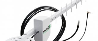
Modem antenna - the best device for signal amplification
Is it possible to make an antenna for 3G and 4G yourself?
Some people think that it is impossible to make an Internet amplifier at home. Such people believe that for this you need to be well versed in physics and radio engineering.
In fact, even a person with scant technical knowledge and without special practical skills can make an antenna on their own to improve network reception. However, despite this, you will still have to familiarize yourself in advance with the step-by-step instructions for making such receivers and the features of their operation.
About the range of Wi-Fi antennas
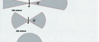
From a native router antenna of 2 dBi, a 2.4 GHz signal of the 802.11n standard can spread over 400 meters within line of sight. Signals of 2.4 GHz, old standards 802.11b, 802.11g, travel worse, having half the range compared to 802.11n.
Considering a WiFi antenna to be an isotropic emitter - an ideal source that distributes electromagnetic energy evenly in all directions, you can be guided by the logarithmic formula for converting dBi to power gain.
Isotropic decibel (dBi) is the antenna gain, determined as the ratio of the amplified electromagnetic signal to its original value multiplied by ten.
AdBi = 10lg(A1/A0)
Conversion of dBi antennas into power gain.
| A,dBi | 30 | 20 | 18 | 16 | 15 | 14 | 13 | 12 | 10 | 9 | 6 | 5 | 3 | 2 | 1 |
| A1/A0 | 1000 | 100 | ≈64 | ≈40 | ≈32 | ≈25 | ≈20 | ≈16 | 10 | ≈8 | ≈4 | ≈3.2 | ≈2 | ≈1.6 | ≈1.26 |
Judging by the table, it is easy to conclude that a directional WiFi transmitter with a maximum permissible power of 20 dBi can distribute a signal over a distance of 25 km in the absence of obstacles.
A further increase in antenna power is unreasonable; the signal will propagate in too narrow a disk-shaped zone.
Author: Vitaly Petrovich, Ukraine, Lisichansk
What is a homemade receiver?
An antenna is a special device that can be used to greatly enhance the signal reception level on the modem. Depending on the installation method, they can be divided into two main categories:
- Rooms. Compact device for indoor use. It is equipped with a powerful amplifier to receive even the weakest signal.
- Street. Most often they are placed on the roof of the house. The size is several times larger than indoor ones.
Important! You can make both indoor and outdoor receivers yourself. The main thing is to have a diagram of the device.
Directed
9 dBi antennas only work in a given direction (directional) - they are useless in a room, they are better used for long-distance communications, in the yard, in the garage next to the house. The directional antenna will need to be adjusted during installation to transmit a clear signal in the desired direction.
Now to the question of carrier frequency. Which antenna will work better at long range, 2.4 or 5 GHz?
Now there are new routers operating at double the frequency of 5 GHz. These routers are still new and are good for high-speed data transfer. But the 5 GHz signal is not very good for long distances, as it fades faster than 2.4 GHz.
Therefore, old 2.4 GHz routers will work better in long-range mode than new high-speed 5 GHz ones.
Homemade receiver options
Before making a means to improve the signal, you need to familiarize yourself with the types of homemade questionnaires.
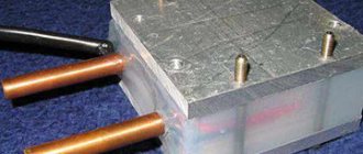
With copper winding
Copper wire - often used when creating homemade receivers.
This is a budget option, which is the easiest to make yourself from improvised means. The device must be equipped with a long reflector, since the quality of signal reception depends on it.
Another important detail that should not be forgotten is copper wire. It is wound over the mast. It is recommended to use wire with a diameter of 2-3 millimeters.
From wire
This option also uses copper wire. It is bent at an angle of 45 degrees to end up with a diamond-shaped design. It is then attached to a wooden or metal frame and connected to an amplifier. Such a design is capable of picking up a signal at a distance of 20-30 km from the tower.
Modification without feeder
Most purchased antennas for the Internet and television are equipped with a special feeder. However, it is not necessary to use it. Devices that are not equipped with it operate at a frequency of 300 Hz.
Modifications without a feeder must be made with copper or aluminum winding. It is placed on a mast with a diameter of 23-25 mm.
Double core
Reflectors - help to strengthen the signal.
This model is most often used for installation outdoors. Its operating frequency is about 400 Hz. It differs from other modifications by the presence of a diamond vibrator. The design also contains several metal gratings 30-40 cm long.
Important! To make the signal better and more stable, reflectors must be installed in models with a double core.
Vertically polarized and braided
If configured correctly, such a panel antenna will be able to output 300 Hz. As in the previous version, special vibrators and metal grids are used here, which help improve signal reception. An aluminum winding is installed on the mast.
There are also side racks that are tilted at 45 degrees.
Vertical polarization without braid
This modification is suitable for modems that operate at a frequency of no more than 200 Hz. The structure consists of side metal posts and an aluminum plate. It is customary to connect it to the modem with a special two-wire cable.
Antenna Kharchenko
This is a universal device that is capable of operating in the frequency range from 450 to 900 MHz. The structure is made of copper wire with a diameter of 4 mm. It must be bent in such a way that the result is a figure eight. It is attached to an aluminum plate. The device is connected to the modem with a cable that can withstand a resistance of 50 ohms.
Log-periodic
Kharchenko's modification is the most popular homemade antenna.
This device is considered a high-frequency receiver. It receives a signal in only one direction, but at the same time picks up a wide range of frequencies.
The design consists of several metal tubes that are located parallel to each other. The longest tubes are located at the base. The shortest ones are on the edge.
Signal amplification features
The shield has a significant influence on the antenna strength. The quality of data transmission can also be improved by directing the vibrator. To do this, when the modem is already connected to the phone, computer or tablet, the antenna plane must be facing the nearest communication center, taking into account polarization.
When there are multiple operators in the area where the antenna is used, they often use different polarizations to prevent interference. The further away the desired station is located, the more the angle of inclination and rotation of the antenna affects the quality of the Internet. Hills, groves and other obstacles in the countryside located in the signal path are also important. According to experts, the optimal antenna direction angle values can vary from 45 to 70 degrees.
DIY making
Before you make your own antenna for mobile Internet, you need to figure out how to do it correctly.
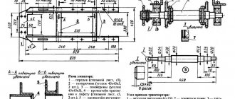
Device and optimal dimensions
Many people believe that the dimensions of the antenna do not affect anything, but this is far from the case. In fact, the level of signal amplification largely depends on the size. Therefore, the device should be made larger. Recommended width and length are about 30 cm.
Important! If you need a compact antenna, you can use Kharchenko’s biquadratic drawing. It is ideal for receiving mobile Internet for your phone.
Vibrator requirements
It is recommended to make it from large copper or aluminum. An ordinary solid rod or tube is used as the body of the vibrator. If you don’t have copper or aluminum at hand, you can make a device from the “whiskers” from a Polish antenna.
The diameter must be at least 4 mm. In this case, it will be possible to achieve a stable signal without interruptions.
Cable selection
The connection cable should not be too thick.
Particular attention should be paid to the cable that will connect the antenna. It is recommended to use cables with low resistance, about 55 ohms. They do not emit interference and do not degrade signal quality. The wires used must be equipped with an F female-CRC9 connector.
Specifics of the reflector design
The reflector is a panel whose surface is covered with foil. The basic requirements for reflectors are as follows:
- they should be slightly larger than the antenna;
- distance to the vibrator - at least 30 mm;
- the structure is slightly bent near the central part.
Important! Reflectors should only be made from metal.
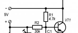
Connecting to a router
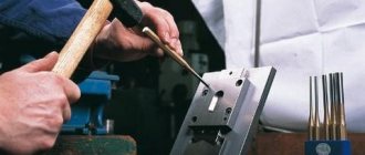
Those who have experience can easily solder to the contact pads on the circuit board inside the router.
Otherwise, be careful, thin traces may come off the printed circuit board when heated for a long time with a soldering iron.
You can connect to an already soldered piece of cable from a native antenna via an SMA connector. You shouldn't have any problems purchasing any other N-type RF connector from your local electronics store.
Creation process and verification
The antenna manufacturing process consists of several sequential steps:
- Determine the perimeter of the antenna square. For a regular 4G modem this is 140-145 mm.
- Creation of the "eight". It is better to make it from copper rods. The length of each side of the created structure should not be less than 30 mm.
- Connecting the cable. It is soldered to the ends of the antenna. A USB connector for the modem is attached to the second end of the cable.
- Installation of a reflector with a vibrator. They are placed in .
The assembled structure must be attached to the rack. Its height depends on where the receiver will be installed.
Additional Information! To check that the assembled device really works, it is connected to the modem. If the signal improves, then everything was done correctly.
Connection and signal transmission options
USB connector - often used when connecting an antenna to a modem
After creating a receiver, some people encounter difficulties connecting it. The devices must be connected using connectors that are suitable for the modem. USB is most often used, as it is the most popular modern connector.
Send data wirelessly
Instead of connecting the receiver to the modem with a cable, you can transfer data wirelessly. To do this, two electrodes 40-50 mm long are connected to the device. After they are soldered to the structure, they are moved apart. After this, you can check whether the wireless Internet will work on your tablet or smartphone.
Device Features
There are different types of homemade devices for strengthening a mobile signal, the most common of which are:
- Kharchenko antenna;
- MIMO amplifier;
- disk antenna or “Gun”;
- Turkin-Polyakov amplifier;
- Uda Yagi wave antenna;
- panel amplifier.
These universal tools allow you to speed up the Internet in rural areas, outdoors and other places with poor access to a mobile network. If there is no connection with the operator or outside its coverage area, these devices will be useless.
A homemade signal amplifier can significantly increase the efficiency of the connection; it is suitable for creating a wireless network and distributing the Internet from a router. To use such an antenna, you just need to connect it to the appropriate connector of the modem. The selection of a plug or pigtail adapter depends on the device model. In some cases, its entrances are closed with a housing, which is removed or small holes are made in it.
The degree of improvement in communication depends on compliance with the assembly instructions, the dimensions and materials of the selected components, as well as the nuances of installing the device. For greater efficiency, some of the parameters of its components are identified through preliminary calculations.
Next, we examine in detail one of the most popular simple 4G signal amplifiers using Kharchenko technology and its manufacturing process. It was originally intended to improve television reception, but the same design is suitable for improving access to modern wireless networks. Brief recommendations and descriptions for the simplest and more demanding powerful amplifier options are also provided.
USB extension cable
In this case, you need to assemble a kind of analogue of a satellite dish. A CD or any metal surface can be used as a reflective surface. Extension cord assembly steps:
- Make a mount for a flash drive in the middle of the disk. Simple tape will do.
- Connect one end of the USB cable to the computer, and the other to the modem.
- Install the disk outside the premises. It is advisable to point the flash drive towards the tower.
The principle of operation of a pigtail for a modem
Routers must have a special connector to connect it to the pigtail.
Disadvantages of this connection method:
It is rarely connected directly to the antenna cable, since the 4G modem is a small device and the best way to connect it is through the appropriate adapter.
The antenna wire is hard and has a diameter of 7 to 10 mm, which will not allow inserting a plug for a 4g modem, so you have to use a short adapter made of soft wire - a pigtail.
Note! The function of the cable adapter is to provide a flexible connection between the USB modem and the radio antenna, the wire of which is usually thick and rigid.
Video
DIY digital TV antenna
Coffee capsule Nescafe Dolce Gusto Cappuccino, 3 packs of 16 capsules
1305 ₽ More details
Coffee capsules Nescafe Dolce Gusto Cappuccino, 8 servings (16 capsules)
435 ₽ More details
Control panels
N-type connector crimping
Let's start crimping the N-type male .
We take the H155 cable and put a heat shrink tube and a crimp sleeve on it.
To prevent the screen braid from shorting onto the central core, you need to trim its ends a little. To do this, spread the braid on two sides and trim the ends with scissors.
Straighten the screen braid and foil.
Place the pin that is included with the N-type male connector onto the central core.
Crimp the pin with pliers.
Check that you have crimped the plug well and that it is firmly attached to the center core.
Insert the plug into the connector, and place the shield braid on the connector body.
Place the crimp sleeve that you put on the cable at the very beginning onto the braid and crimp the sleeve with pliers.
Place the heat shrink tubing onto the crimp sleeve and heat shrink it using a lighter.
One pigtail connector is ready. If there are traces of soot on the heat shrink tube after using the lighter, wipe it off with a napkin or rag.
How to determine what pigtail is needed?
On the antenna wire side, these are usually F or SMA sockets; the modem uses CRC9 or TS9 type sockets for connection.
Antenna connectors are not universal, due to the fact that each manufacturer of mobile devices puts connectors on their products that are structurally different from competitors, as a result, it turns out that each device requires its own special adapter.
Their main differences are:
Note! Huawei uses mainly the CRC9 connector in its mobile devices, while Novatel Wireless uses mainly the TS9 connector.
The connectors on the antenna wire side also come in different types. This can be F and FME models. For type F connection, an F adapter is screwed onto the cable side.
The CRC9-F antenna adapter is suitable for all modems and routers in which the pigtail connector for a 4g modem is connected to the device port with a CRC-9 tip. F is the designation of the connector on the other end of the adapter for connecting to the antenna wire.
The TS9 FME adapter has a TS9 connector on the side connecting to the modem, and an FME connector on the side connecting to the radio antenna.
Receiving and sending information in wireless communication lines
Radio waves, when moving in space, encounter various obstacles in the form of houses, trees and other structures. Obstacles along the way can reflect or absorb the wave, or do so partially. Sometimes the signal is split into several component parts. The nature of the interactions between the wave and obstacles along the way is influenced by the surface material, signal frequency and many other factors. Reflection during transmission causes time delays to occur. In addition, due to all these interactions, only a portion of the waves sent from the receiver reaches the end user. Therefore, one of the main problems of wireless networks is multipath signal propagation.
Problems transmitting and receiving a mobile Internet signal
To solve this problem, the following technologies are used:
- Receive Diversity allows you to receive a signal by several devices at once, rather than just one. Thus, waves not received by one antenna are received by the other. The principle of one output and multiple inputs, or SIMO (Single Input Multiple Output) is used;
- Diversity transmission (Tx Diversity) is based on the fact that the signal is sent from several antennas and received by one, that is, multiple output and single input, or MISO (Multiple Input Single Output), like a 3G panel antenna;
- Spatial Multiplexing – splitting the output stream into several components and receiving through several devices, or MIMO. The antenna receives a signal intended for other receiving devices too. Using the transmission matrix and all the information received, the signal is restored as much as possible.
To determine the maximum throughput - C, the formula is used:
С= MB log2(1 + S/N), where:
- C – channel capacity;
- M – number of independent data streams;
- B – channel width;
- S/N – signal/noise ratio.
For 4G cellular communications, namely LTE MIMO, it is possible to use 8X8, which allows you to achieve speeds of up to 300 Mbit/s. Even at a considerable distance from the station, the signal will be stable. Today MIMO 2X2 is more common. Always for 4G the number of channels must be even.
How do antennas work to transmit and receive signals?
Antennas can be located on the same surface or be vertically spaced. In the second case, it is important to accurately maintain the differences in degrees indicated in the diagram.
Protection
To protect from external influences, the remote antenna must be placed in a housing of suitable dimensions. The exit points of the cable and fasteners must be carefully sealed.
Important! The body of the structure must be made of non-conductive material. It can be polystyrene or polyethylene
The first material is preferable because it allows the body to be assembled by gluing and is sufficiently resistant to ultraviolet rays, low and high temperatures.
External devices are at their greatest risk during a thunderstorm. A lightning strike that hits an antenna can instantly damage the internal circuits of all equipment connected to it. Therefore, if there is a possibility of a thunderstorm, you should disconnect the antenna cable from the modem or router connector.
Homemade devices for increasing the received signal power can improve the quality of reception, the speed of reception and data transmission, eliminating additional costs for more advanced equipment.
Crimping RP-SMA connector
the RP-SMA male connector .
We put a heat shrink tube and a crimp sleeve on the H155 cable.
To prevent the screen braid from shorting onto the central core, you need to trim its ends a little. To do this, spread the braid on two sides and trim the ends with scissors.
Straighten the screen braid and foil.
Place the socket part, which is included in the RP-SMA male connector kit, onto the central core.
Crimp the nesting part with pliers.
Check that you have crimped the socket part well and that it is firmly attached to the center core.
Insert the female part into the connector and place the shield braid on the connector body.
Place the crimp sleeve that was put on the cable at the very beginning onto the braid and crimp the sleeve with pliers.
Place the heat shrink tubing onto the crimp sleeve and heat shrink it using a lighter.
The second pigtail connector is ready. If there are traces of soot on the heat shrink tube after using the lighter, wipe it off with a napkin or rag.
Now we have a finished pigtail.
Next you need to check the quality of the pigtail. A tester will help us with this; it needs to be set to ringing mode.
Let's check that the central core and braid are not shorted. Touch the probes to the central core plug and the connector body. The tester should not beep.
Now let's check that the connectors are connected to each other. Touch the probes to the body of one and the second connector. The tester should beep.
Touch the probes to the plug of one connector and the female part of the second connector. The tester should beep.
Next, connect one end of the pigtail to a Wi-Fi router or Wi-Fi adapter.
We connect the second end of the pigtail to an external antenna.
Source