Today, there are quite a lot of different battery-powered devices. And it’s even more annoying when, at the most inopportune moment, our device stops working, because the batteries are simply dead, and their charge is not enough for the normal functioning of the device.
Buying new batteries every time is quite expensive, but trying to make a homemade device for charging finger batteries with your own hands is quite worth it.
Many craftsmen note that it is preferable to charge such batteries (AA or AAA) using direct current, because this mode is most beneficial in terms of safety for the batteries themselves . In general, the transferred charge power from the network is about 1.2-1.6 times the capacity of the battery itself. For example, a nickel-cadmium battery with a capacity of 1A/h will be charged with a current of 1.6A/h. Moreover, the lower the given power, the better for the charging process.
Homemade charger for AA batteries
Today, there are quite a lot of different battery-powered devices. And it’s even more annoying when, at the most inopportune moment, our device stops working, because the batteries are simply dead, and their charge is not enough for the normal functioning of the device.
Buying new batteries every time is quite expensive, but trying to make a homemade device for charging finger batteries with your own hands is quite worth it.
Many craftsmen note that it is preferable to charge such batteries (AA or AAA) using direct current, because this mode is most beneficial in terms of safety for the batteries themselves .
In general, the transferred charge power from the network is about 1.2-1.6 times the capacity of the battery itself. For example, a nickel-cadmium battery with a capacity of 1A/h will be charged with a current of 1.6A/h.
Moreover, the lower the given power, the better for the charging process.
- 1 Manufacturing process
- 2 Charging from USB port
- 3 Conclusion
Manufacturing process
In the modern world, there are quite a lot of household appliances equipped with a special timer that counts down a certain period, then signaling its end. When making your own device for charging AA batteries, you can also use this technology , which will notify you when the battery charging process is complete.
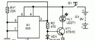
The charger for AA batteries is a device that generates direct current, charging up to 3 A/h. During production, the most common, even classic, scheme was used, which you see below. The basis, in this case, is the transistor VT1.
The voltage on this transistor is indicated by a red LED VD5, which acts as an indicator when the device is connected to the network. Resistor R1 sets a certain power of currents passing through this LED, as a result of which the voltage in it fluctuates.
The value of the collector current is formed by the resistance from R2 to R5, which are included in VT2 - the so-called “emitter circuit”. At the same time, by changing the resistance values, you can control the degree of charging. R2 is constantly connected to VT1, setting a constant current with a minimum value of 70 mA.
To increase the charging power, it is necessary to connect the remaining resistors, i.e. R3,R4 and R5.
Safety precautions
Factory chargers are safe to use. From this point of view, homemade devices are not so reliable and this is their main drawback. When working with them, you should follow several safety rules:
- The battery and charger must be placed on a fireproof surface.
- When working with the simplest device, you should use personal protective equipment - a rubber mat and insulating gloves.
- When using the charger for the first time, you must carefully monitor the charging progress.
- The main parameters that should be monitored are current, voltage at the battery terminals, temperature of the charger case and battery.
- If you plan to leave the homemade charger overnight, it is necessary to provide an emergency shutdown system.
A properly assembled homemade charger can be a good alternative to a factory-made device. In addition, by using scrap materials and parts from failed devices, you can save a lot of money.
How to make a charger for AAA batteries with your own hands at home - Do it yourself
25.10.2019
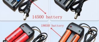
Li-ion 18650 batteries are very widely used in many of the electronic devices we use today. For example, LED lights, laptop batteries, electric bicycles or Power Bank.
These batteries are a reliable source of power, so they are also very convenient to use in DIY projects. The shape of 18650 lithium-ion batteries resembles a AA battery, but the output voltage is 3.7 V with a capacity of 1600 to 3600 mAh (AA or AAA batteries have a voltage of 1.5 V/1.2 V).
However, at the moment, charging these batteries is still not an easy matter as commercial chargers are quite expensive. In addition, lithium-ion batteries require a good quality charger, otherwise the battery life will be degraded. A balanced charger works well, but it is available at a higher price range.
So in this tutorial we decided to make a Li-Ion charger that can charge four 18650s at the same time. This charger is very easy to make and does the job of a balanced charger by cutting off power to individual batteries once fully charged.
Step 1: Accessories
We will need several “spare parts” for our charger:
- general purpose printed circuit board
- module TP4056
- paper clips
- connector
- PCB switches
- 3.7V Li-Ion batteries
- Soldering iron
You can buy all this in different stores, especially in foreign ones, for example, Amazon or E-bay.
Step 2: Let's start collecting
- Take a general purpose PCB and place the batteries on top of the board;
- Mark the distance between the edges of the batteries and their width on the circuit board;
- Unfold 8 paper clips and use pliers to cut clips from the edges as seen in the image above;
- A total of 8 U-clamps must be made (depending on the number of batteries being charged);
- Insert the U-shaped clamps into the circuit board so that the batteries can be installed between the clamps;
- The clips will act as battery holders;
- Also, use leftover pieces from the paperclips to make side supports;
- Attach the clamps well to the board as shown in the picture.
Note: Make sure the clamps are not connected to each other while soldering.
- Place the TP4056 charging module on the PCB as shown in the picture above;
- Using a marker, mark the module holes on the board;
- Solder a pin into each of the marked holes;
- Insert the module over the pins and solder carefully;
- Use the number of modules equal to the number of batteries being charged, i.e. one module per battery;
- Solder all modules onto the board as shown in the picture;
- Take the switches and solder them between each module on the PCB.
Note: Be sure to watch the video (below) and look at the images to avoid any mistakes.
- Refer to the wiring diagram above and solder all components together;
- Be sure to mark the polarity on the U-clip battery holders;
- Connect the terminals of the battery holder to the input terminals of the TP4056 charging module according to the polarity;
- Connect the modules so that they can transfer power from one stationary charger;
- Also, install connections between switches so that they can be used to independently control the power of the modules.
Step 5: Test the charger
- Insert the batteries into the battery holders on the board;
- Connect the mobile phone charger to one of the modules and turn on the power;
- An indicator will light on the module to indicate charging;
- Use switches to control the power supplied to the batteries;
- Turn off all switches if you only want to charge one battery;
- Turn on the switches according to the amount of battery charge at a certain time;
- Because each battery has a separate charger, so they will never face the problem of overcharging and recharging (the most common problem that damages lithium-ion cells).
Note: The TP4056 charging module is capable of providing 1A at 5V. Since we made the charger for 4 batteries, it is necessary to use a 2A mobile charger, such that at least 500mA is supplied to each cell.
So, friends, this concludes the lesson. Make it at home and use any number of lithium-ion cells without worrying about charging it.
Hello, dear readers of the site sesaga.ru. Lithium-ion (Li-Ion), nickel-cadmium (Ni-Cd) and nickel-metal hydride (Ni-Mh) batteries are widely used to power portable small-sized radio equipment. If the charging rules are followed, they last for several years and can withstand about 1000 charge-discharge cycles.
However, nickel-based batteries, such as Ni-Cd, require a special approach, as they have a “voltage depression” effect, which is also called the “memory effect”. The “memory effect” occurs during battery operation if it is systematically recharged without discharging
up to a voltage of 0.9 - 1 V [1].
Those. If you charge a battery that is not completely discharged, it will release energy only to the level from which charging began.
And since they are generally recharged this way, without going through full charge-discharge cycles, over time this level only increases, causing the battery capacity to decrease, which is why the user comes to the conclusion that the battery is beginning to deteriorate.
However, you should not be afraid of this electrochemical process, since it accumulates, is reversible and can be easily eliminated. To reduce the occurrence of the “memory effect,” manufacturers recommend periodically discharging batteries to a voltage of 0.9 - 1 V, and then charging them to 1.45 - 1.48 V.
The proposed simple universal charger allows you to partially automate this process and charge and discharge Ni-Cd and Ni-Mh batteries with a current of up to 260 mA.
Description of operation and device diagram
During operation, the charger constantly monitors the voltage on the battery being charged and automatically turns off the current when fully charged. It allows you to simultaneously and independently charge and discharge two AA or AAA batteries. The schematic diagram of the device is shown in the figure.
Functionally, it is designed as two channels with a common power supply, each having one charging
and
discharges
.
All switching for the charging and discharging processes is made by switches SA1
and
SA2
, and a cell phone charger with a stabilized output voltage of 5 V and a current of at least 1 A is used as a power source.
Let's consider the operation of one channel and start with the charging node [2]. While charging
The voltage on the battery being charged is monitored continuously.
On transistors VT1
and
VT2
a Schmitt trigger is assembled, which compares the voltage on the charging battery
GB1
or
GB2
with the reference voltage supplied to the
VT1
from the trimmer resistor
R2
.
The reference voltage is formed by the zener diode VD1
, resistors
R1
and
R2
.
Resistor R1
sets the operating current of the zener diode (about 10 mA), and resistor
R2
sets the desired threshold voltage.
When connecting a discharged battery to a charger, transistor VT2
closed, and
VT1
and
VT3
are open.
The collector current of transistor VT3
through the closed contact
SA2.1
of switch
SA2
charges the battery.
As soon as the voltage on the battery reaches a predetermined threshold value, the trigger and transistors VT1
,
VT3
will close, and
VT2
will open and turn on the
HL1
, signaling the end of charging.
Switch SA1
select the battery size and set the required charging current to 110 or 260 mA.
In the closed position of contact SA1.2
charging is carried out with a current of 110 mA, which allows you to charge batteries with a capacity of 850, 1100 and 1600 mA/h.
In the closed position of contact SA1.1,
charging is carried out with a current of 260 mA, which allows charging batteries with a capacity of 2100, 2600, 2700 and 2850 mA/h.
Switch SA2
charging
or
discharging
modes .
Push-button switch SB1
designed to force the charger to start if the battery is not completely discharged. Pressing the switch sets the trigger to the state corresponding to the charging mode.
Now let's look at the operation of the discharge unit
, which is powered by a discharged battery and when its voltage reaches 0.9 - 1.1 V, it automatically stops the discharge process [3].
When you briefly press the SB2
voltage from battery
GB1
or
GB2
to the base of transistor
VT5
through resistor
R11 .
If it exceeds the opening threshold of transistor VT5
(approximately 0.6 V), it opens and opens transistor
VT4
, through the collector-emitter section of which the battery discharges.
As the battery discharges, the voltage on it decreases, and when it drops below the opening threshold of the transistor VT5
, it closes and closes
VT4
.
The discharge process stops. HL3
incandescent lamp with a rated voltage of 1 V is used as a load and indicator of the operation of the discharge unit. Lamps with a voltage of 1.5 and 2 V can also be used.
Instead of a lamp, you can install a resistor with a resistance of 20 - 30 Ohms. In this case, there will be no indication and you will have to periodically check the voltage on the discharged battery.
Construction and details
The charge-discharge device is mounted on a printed circuit board made of single-sided foil fiberglass laminate measuring 60x45 mm and placed in a plastic case. Due to the simplicity of the circuit, the device can be assembled on a breadboard or even mounted.
The PCB is designed for two channels and its drawing is provided. Element labeling is shown for only one channel, since the second channel is identical.
The following figure shows the location of parts on the board, as well as their markings according to the circuit diagram.
Battery compartments, LED and incandescent lamps, as well as switches and push-button switches are located on the outer part of the housing. The battery compartments are first glued to the case with glue, and then additionally secured with screws. Screws are used with countersunk heads.
The installation of battery compartments and switches is carried out by hinged mounting directly inside the case. Push-button switches are located at the rear of the housing and are connected to the printed circuit board by a flexible wire.
The device uses resistors with a power of 0.125 W. Resistor R2 is a multi-turn trimmer of any type. Instead of transistors KT315B (VT1, VT2) and KT814B (VT3), you can use any with similar parameters. KT814 transistors are equipped with heat sinks.
We can replace the KT502 (VT4) transistor with any silicon one with a maximum collector current of at least 150 mA. The KT3102G (VT5) transistor was selected with an increased current coefficient and can be replaced with any one with similar parameters.
The device is connected to the power supply using a regular USB cable. The connector that is used to connect to the phone is cut off and the red and black wires are used to supply power. The red vein is a plus, and the black vein is a minus.
Setting up
If the device is assembled correctly and from serviceable parts, installation is reduced only to setting the reference voltage level
and, if required, setting
the charging currents
for finger and little finger batteries.
To set up the device, you must have a finger and little finger batteries. The finger type should be charged to a voltage of 1.48 - 1.49 V.
If there is no charger, then the battery is charged by this charger to a voltage of 1.48 - 1.49 V. During the charging process, the voltage on the battery is monitored by a measuring device. As soon as it is charged to the specified value, you can begin setting up.
Setting the reference voltage level
HL1 LEDs should light up
and
HL2
of both channels. A AA battery charged to a voltage of 1.48 - 1.49 V is inserted into the battery compartment and the reference voltage level of the first channel is adjusted.
Rotate the slider of trimming resistor R2
make the
HL1
. Then, by slowly rotating the engine in the opposite direction, the LED turns on. For accuracy of adjustment, this operation is repeated 2 - 3 times.
Now the battery is inserted into the compartment of the second channel and configured in the same way.
Setting the battery charging current
For ease of adjustment during installation, the terminals of the power transistor VT3
temporarily soldered to the board with pieces of mounting wire 70 - 80 mm long. The collector output wire is cut in half and a milliammeter with a measurement limit of at least 500 mA is connected to its ends.
Switch SA2
the first channel is switched to the “Charge” position, and
SA1
is switched to the “260” position and power is supplied to the device.
Next, take a discharged battery with a capacity of 2100 - 2850 mA/h, insert it into the appropriate box and monitor the charging current using a milliammeter. If the current is in the range of 250 - 270 mA, then do nothing. If the current is below the limit, the resistance of resistor R3
increase by several tens of ohms, if higher - decrease.
Then switch SA1
switch to position “110”, insert a discharged little finger battery with a capacity of 850 - 1100 mA/h into the corresponding box and adjust the charging current in the same way with resistor
R4
so that it is within 100 - 120 mA.
The second channel is configured in the same way. Now remove power from the charger and power transistor VT3
soldered into place as expected.
Setting the battery discharge current
All that remains is to check and, if necessary, adjust the discharge current
.
The device is not receiving power. The switch of the first channel SA2
is moved to the “Discharge” position, and the emitter circuit of transistor
VT4
is broken and a milliammeter with a measurement limit of at least 200 mA is connected to the gap.
The “Start” button starts the device and uses a milliammeter to control the battery discharge current, which should be within 80 - 100 mA. If the discharge current is higher, then a resistor with a resistance of 15 - 47 Ohms is connected in parallel with the lamp. The second channel is configured in the same way.
If you have any questions, be sure to watch this video.
That's all. Good luck!
Literature:
1. B. Stepanov, “Radio”, 2006, No. 5, p. 34, Let’s extend the “life” of Ni-Cd batteries! 2. V. Kosolapov, “Radio”, 1999, No. 2, p. 36, Simple charger.
3. A. S. Partin and L. Partina, “Radiomir”, 2007, No. 11, p. 13, Automatic “discharger”.
Danger of overcharging lithium cells
Lithium cells must be handled with care because they concentrate a lot of energy into a small area when fully charged. Therefore, protected Li-ion and Li-pol batteries have been on sale for a long time.
Back in 1991, Sony drew attention to the explosion hazard of Li-ion cells. Currently, all batteries without exception are wound with a two-layer separator between the plates to eliminate the risk of internal short circuit
All branded batteries are equipped with a field-effect transistor protection board, which turns them off in the following cases:
- The battery is excessively discharged - below 2.5 V.
- Overcharged - over 4.2 V.
- The charging current is too high - more than 1C (C is the battery capacity in Ah).
- Short circuit.
- The load current is exceeded - more than 5C.
- Incorrect polarity when charging.
For additional security, there is a thermal fuse that opens the circuit when the lithium element overheats above 90 °C.
Making a homemade charger for AA batteries
First, let's find out what a battery is. We open the relevant literature and read:
Ozhegov's Dictionary:
- Small rechargeable battery.
Ushakov's Dictionary:
- Small electric battery for flashlight.
Efremova's dictionary:
- A small battery device for increasing voltage or supplying energy.
Yes, it's a complete mess. Mrs. Efremova’s definition is especially touching. We won’t get help from the great and mighty “bisons”. And all because, from a technical point of view, the concept of “battery” does not exist.
Most of those who are far from electrical engineering use this diminutive word to call almost all autonomous current sources - from galvanic cells to batteries and batteries assembled from them. With one condition, that such a source fits into your pocket.
For example, no one would call a car battery a battery. This is a Battery with a capital B!
More advanced users use the word “battery” only to refer to galvanic cells and batteries assembled from them, but do not touch batteries and rechargeable batteries.
So what are all these devices actually called? The issue is resolved simply. It is enough to understand two definitions:
- A galvanic cell is a single device that generates electrical energy through internal irreversible chemical processes.
- A battery is a single device capable of storing electrical energy through internal chemical changes and subsequently releasing it through reverse chemical processes.
In other words, something disposable (worked and thrown away) is a galvanic cell. Something that can be charged repeatedly is a battery. If the elements are connected to each other according to one scheme or another, then this design is called a battery. For galvanic cells – a battery of galvanic cells. For batteries – a battery of batteries or a rechargeable battery.
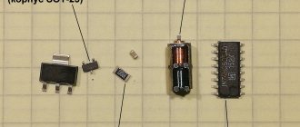
Thus, in the topmost photo in the first and second positions from left to right there are batteries of galvanic cells. The first is assembled from 6 elements, the second (it is often called flat) - from three.
The third position shows a nickel-cadmium battery, the fourth and fifth positions show galvanic cells, and the last position shows a battery consisting of two nickel-metal hydride batteries.
But with a clear conscience we call all this “batteries”, and then we get offended when they can’t understand us! As for the car battery, which, oddly enough, is not called a “battery”, it is precisely a battery consisting of six batteries (popularly called “banks”).
Expert opinion
Alexey Bartosh
Specialist in repair and maintenance of electrical equipment and industrial electronics.
Ask a Question
Interesting. Many people believe that mobile devices contain batteries (note, not just any “batteries”). In fact, all smartphones, telephones and other similar equipment contain single batteries, not batteries. An exception may be a laptop battery, consisting of a set of single batteries.
On the left is a battery for a phone, on the right is a battery for a laptop, consisting of six batteries
Main characteristics of batteries
We've sorted out the terminology, now let's see what types of batteries there are and how they differ from each other.
Form factor
Modern batteries - both galvanic cells and batteries based on them - are available in various form factors. The most common are cylindrical and disk. Some batteries may be rectangular in shape.
The most popular sizes of galvanic cells and batteries
Charging galvanic cells is not only useless, but also dangerous.
If you force a battery to do something for which it is not intended, for example, forcefully “fill” voltage into it, then the cell may lose its seal and “leak,” flooding everything with electrolyte. But this is also a lesser evil.
It’s much worse when, when trying to charge, the battery overheats and explodes. Here it’s not far from an injury, and a stone’s throw from a fire. Thus, under no circumstances should you charge a completely discharged galvanic cell.
But it is not all that bad. Yes, a disposable battery cannot be restored, but it can be recharged without waiting for it to completely discharge. By recharging periodically, it is quite possible to extend the life of the galvanic cell by double or even triple.
Where does the extra energy come from in a battery whose chemical reactions are irreversible? The fact is that during the operation of the galvanic cell, the starting materials are not fully used.
Even a completely discharged battery still has a lot of untapped potential. If the battery is completely dead, it will not be possible to revive it.
But if the element is periodically “shake” with small charging currents, then it will use up the components more fully and will be able to last longer.
Important! Even recharging a galvanic cell may carry a certain danger of an explosion or fire. Therefore, if we nevertheless decide to do this, we must clearly understand that we are doing this at our own peril and risk.
How to distinguish a disposable battery from a rechargeable battery
We found out what the batteries that can be recharged are called. Their name is batteries. But how to distinguish a galvanic cell from a battery, especially if both are made in the same form factor? This is not difficult to do.
By voltage
No battery produces exactly 1.5 V. It can be 1.2, 1.6, 3.2, 3.7 V, but never 1.5 (see the “Output Voltage” section). If the cell body indicates a voltage of 1.5 V, then this is clearly not a battery. But this rule does not work for batteries. If a battery consists of several cells, then its output voltage can take on different values.
Thus, it is quite difficult to clearly distinguish a rechargeable battery from a battery of galvanic cells by voltage.
According to the accompanying inscriptions
Almost always, the manufacturer indicates its electrical capacity on the battery case. There are no such inscriptions on disposable batteries.
In addition, the type of battery is always indicated - the composition of the electrolyte and the material of the electrodes. In the photo below, we see a nickel-metal hydride battery on the left, and a lithium-ion battery on the right.
| [td] Sergey Chernov, Samara km450 (At) mail. ru |
Many diagrams of devices for charging nickel-cadmium pen-type (Ni-Cd) batteries have been published. But when the need arose to assemble a charger for myself, I couldn’t find anything to my taste.
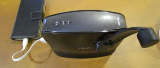
You can, of course, buy a ready-made one, but this is not for a radio amateur. I had to develop my own. The proposed device is designed to charge AA batteries of all types, operates in automatic mode, is easy to repeat, is small in size and does not contain scarce parts. The appearance of the structure is shown in Fig. 1.
The device is available for repetition by beginning radio amateurs.
Rice. 1.
The device contains two identical battery charging channels, since it was designed specifically for its needs. One is designed to charge two AA batteries with a capacity of up to 2600 mAh, the other three AAA batteries with a capacity of up to 900 mAh. The schematic diagram is shown in Fig. 2.
The device is powered from a 220V network through a small-sized transformer T1 and a rectifier VD1, the output voltage of which at full load is about 9 volts.
Operation is indicated by two two-color LEDs, the red light of which signals the charging process, and the green light indicates its completion.
Rice. 2. Schematic diagram
The DA4 TL431 chip (analogue of LM431) contains a precision reference voltage source, and the DA1 and DA2 LM317T chips contain a charging current stabilizer, the value of which is determined by the battery capacity and is a tenth of it.
The control and indication circuit is assembled on a DA3 LM393, consisting of two open-collector comparators, keys for controlling charging current stabilizers on transistors VT1, VT2, an operation indicator on transistors VT3, VT4 and two-color LEDs VD6, VD7.
Description of work.
When connecting discharged batteries, the voltage at the direct inputs of the comparators is lower than the reference voltage at the invert ones. At the outputs of the comparators, accordingly, there is a zero potential, which leads to the opening of transistors VT1 and VT2.
Current stabilizers are turned on, the value of which is determined by resistors R29-R32. The resistor resistance value in ohms, according to the manufacturer's specifications, is calculated using the formula 1.25v/Ia. The board has space for two resistors for easy selection. I don’t have R32, it’s not useful.
Transistors VT3 and VT4 are closed, LEDs VD6, VD7 glow red.
At the end of charging, transistors VT1 and VT2 close, charging the batteries stops. Transistors VT3 and VT4 open, the LEDs glow green. Next, the batteries are under a small current of the order of 1 mA, which is almost completely safe for them but is necessary for the stable operation of the comparators, and they can remain in this state for a long time.
The comparators have a small hysteresis of the order of 10 mV, determined by resistors R16, R17, R19 and R20. Two resistors are included for ease of selection and reservation of space on the board when wiring it. One per comparator was practically enough. During the design, the PCAD 4.5 program was used.
Soviet charging circuit for AA batteries Elektronika-ZU04
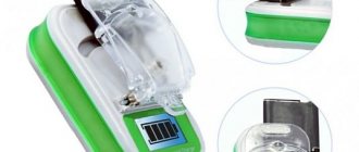
Let's study the charging device "Electronics ZU-04", inside of which a power circuit with a quenching capacitor is implemented.
You can charge any number of batteries from 1 to 4
The device has a strange collapsible design with a detachable plug on springs:
You can charge from 1 to 4 batteries by inserting them into any slots
This is due to the fact that the power supply circuit with a quenching capacitor means that there is a voltage of 220 volts on all contacts and the batteries being charged, so the batteries must be carefully packaged and insulated before plugging it all into the electrical network. The entire body is dotted with relief inscriptions:
Lettering: 220V 50Hz
; Before use, study the passport. ; Before removing the cover, remove the plug from the power outlet; ZU04, 1.2V; Max charge current 90mA
We unscrew two screws and contemplate the inside:
Electrical circuit diagram "Electronics" ZU-04
Measurement results. At the output of the diode bridge, the voltage is 22 volts, the voltage at the zener diodes is 3.8 V (although the 3V0 inscriptions on them mean that they should stabilize at 3.0 V). A current of 55 mA flows through the HL1 LED and the voltage on it is 2.7 V (it is generally abnormal: it has a “ + ” on the thick contact on which the reflector and the radiating junction are located). The voltage across the 120 Ohm resistor (1 W) is 7 V, therefore the current flows through it is 55 mA. Total: 55 through the LED + 55 through this resistor = 110 mA.
Charging works at its full 110 mA even without batteries: this current passes sequentially through all the zener diodes, resistors, and the LED (lit) - so energy is pointlessly allocated to them. But if you install a battery, the corresponding zener diode will turn off (since the voltage on it will become less than 3.0 volts) and current will flow in this place through the battery.
Capacitors K73-17 in the amount of 2 pieces... Why two? Costs of Soviet production technologies: this charger has 90mA and 75mA versions, respectively, they installed one capacitor of these ratings.
Electrical diagram from the manufacturer (scan of suddenly found instructions; the parts stated here do not correspond to the real ones in the diagram above):
Source: https://almois.ru/shema-sovetskoj-zaryadki-aa-akkumulyatorov-elektronika-zu04/
Battery classification
Batteries differ in shape and internal composition, more precisely, in the type of chemical reaction that leads to the formation of electric current.
Types of batteries by shape
- The most familiar to us are “finger” (labeled AA) and “little finger” (labeled AAA). They are cylindrical in shape and power most types of electronic equipment.
- Elements of the “barrel” format (markings C and D) are also produced in the shape of a cylinder, only their sizes are larger, which provides a greater power reserve. Such sources are used, for example, in tourist lamps, radios, players and tape recorders.
- Rectangular galvanic cells, popularly called “crown” - after the name of a famous brand.
- Disc batteries (CR) - the so-called “tablet” batteries, are used in wristwatches, laser pointers, toys
The operating voltage of cylindrical batteries is 1.6 Volts. And the “crown” provides a voltage of as much as 9 volts.
By type of chemical reaction
- Saline. They are characterized by low power and can be stored from 1 to 3 years.
- Alkaline or "alkaline". The name comes from the imported Alkaline marking. They are able to cope with a more powerful load. Shelf life - from 3 to 5 years.
- Lithium. They cope best with high loads. Shelf life is from 5 to 7 years.
What is the difference between a charge controller and a protection circuit?
Some users periodically have a question, put in the title of the section - why do we need a charge controller if there is a protection circuit (individual or general in the form of a balancing board). The fact is that these devices solve different problems :
- the protective module protects the element from overcharging, prevents it from going into a deep discharge, and turns off the battery when the permissible temperature is exceeded;
- The charge controller forms the correct mode of energy replenishment - stabilizes the current at a given level, carries out additional charging according to various algorithms.
And confusion may arise due to the fact that there are cases when some of the functions of these devices are duplicated. Thus, overheating protection can be built into both the protection board and the charge controller. And both the built-in board (disabling the battery) and the charger (completing the process of replenishing energy) can protect against overcharging.
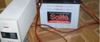
Memory from the ATX power supply (for prepared ones)
A charger made from a computer power supply has a more complex circuit.
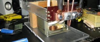
For the manufacture of the device, units with a power of at least 200 Watts of the AT or ATX models, which are controlled by a TL494 or KA7500 controller, are suitable
It is important that the power supply is fully operational. The ST-230WHF model from old PCs performed well
A fragment of the circuit diagram of such a charger is presented below, and we will work on it.
In addition to the power supply, you will also need a potentiometer-regulator, a 27 kOhm trim resistor, two 5 W resistors (5WR2J) and a resistance of 0.2 Ohm or one C5-16MV.
The initial stage of work comes down to disconnecting everything unnecessary, which are the “-5 V”, “+5 V”, “-12 V” and “+12 V” wires.
The resistor indicated in the diagram as R1 (it supplies a voltage of +5 V to pin 1 of the TL494 controller) must be unsoldered, and a prepared 27 kOhm trimmer resistor must be soldered in its place. The +12 V bus must be connected to the upper terminal of this resistor.
Pin 16 of the controller should be disconnected from the common wire, and you also need to cut the connections of pins 14 and 15.
You need to install a potentiometer-regulator in the rear wall of the power supply housing (R10 in the diagram). It must be installed on an insulating plate so that it does not touch the block body.
The wiring for connecting to the network, as well as the wires for connecting the battery, should also be routed through this wall.
To ensure ease of adjustment of the device, from the existing two 5 W resistors on a separate board, you need to make a block of resistors connected in parallel, which will provide an output of 10 W with a resistance of 0.1 Ohm.
Next, the manufactured board is installed in the case and all pins are connected according to the diagram.
Then you should check the correct connection of all terminals and the functionality of the device.
The final work before completing the assembly is to calibrate the device.
To do this, the potentiometer knob should be set to the middle position. After this, the open circuit voltage should be set on the trimmer resistor at 13.8-14.2 V.
If everything is done correctly, then when the battery starts charging, a voltage of 12.4 V with a current of 5.5 A will be supplied to it.
As the battery charges, the voltage will increase to the value set on the trim resistor. As soon as the voltage reaches this value, the current will begin to decrease.
If all operating parameters converge and the device operates normally, all that remains is to close the housing to prevent damage to the internal elements.
This device from the ATX unit is very convenient, because when the battery is fully charged, it will automatically switch to voltage stabilization mode. That is, recharging the battery is completely excluded.
For convenience of work, the device can be additionally equipped with a voltmeter and ammeter.