Stepper motors are widely used in modern industry and homemade products. They are used where it is necessary to ensure the accuracy of the positioning of mechanical components without resorting to feedback and precise measurements. Today I want to talk about a special type of stepper motors - miniature stepper motors, which are used in the design of optical systems. We will take a detailed look at their structure and how to control such tiny motors.
A stepper motor is a brushless electric motor with several windings (phases) located on the stator and magnets (often permanent) on the rotor. By applying voltage to the stator windings, we can fix the position of the rotor, and by applying voltage to the windings sequentially, we can move the rotor from one position to another (step), and this step has a fixed angular value.
We will not dwell on each type of stepper motor. Quite a lot has been written about this on the Internet, for example here.
I want to talk about a special type of stepper motors - miniature stepper motors, which are used in the design of optical systems. Such babies are available for free sale. But on the Internet, especially in Russian, there is very little information on such motors. Therefore, when I needed to use them in my project, I had to do a fair amount of searching for information and conduct a couple of experiments.
I will share the results of my searches and experiments in this article.
We will consider the issues of controlling such small motors, namely:
- L293D driver + ATtiny44 microcontroller;
- TMC2208 driver + ATtiny44 microcontroller;
- ATtiny44 microcontroller (without driver).
Actually, only the last point can raise questions here. Believe me, I was also surprised when I came across a video (here it is) where a guy simply takes and directly connects a stepper motor to the pins of a microcontroller! But let's talk about everything in order.
What is a stepper motor
According to the most popular definition, this is a machine that converts electrical energy (it receives it from the network) into mechanical energy by carrying out discrete (attention, not continuous, this is important) movements of the rotor.
Moreover, after each such action, the position of the dynamic part is fixed. All individual movements are of the same magnitude, and together they form a complete revolution (cycle). Therefore, by counting their number, you can easily and with high accuracy calculate the absolute position of the tool. Their total number, by the way, depends on a number of factors: the nature of the connection, the type of device, the method of specifying commands and other factors.
Operating principle of a stepper motor
- Voltage is applied to the terminals, due to which the special brushes begin to rotate.
- Under the influence of incoming pulses, the rotor is set to its initial position and then moves at the same angle.
- The microcontroller (in most cases, although other external control circuitry is possible) drives the gear magnets. The one to which energy is applied attracts the gear, thereby ensuring the rotation of the shaft.
- The remaining magnets are by default aligned with the leader, so they move along with it towards the next part.
- The gear rotates by switching electromagnets in order - from the main one to the next one and so on. At the same time, it is aligned with the previous wheel, which completes the cycle.
The step of the stepper motor is the algorithm described above, and it is repeated the number of times necessary to complete the technological operation.
An idea of the appearance and nature of functioning will be complemented by the following figure:
It is clear from it that the stator includes four windings arranged crosswise, that is, at an angle of 90 0 to each other. From here it is clear that discrete movement will be carried out by the same amount of degrees. If the voltage is applied alternately - U1, U2, U3 and so on - the rotor will make a full revolution, and then go to the second circle, that is, it will begin to rotate - until it needs to be stopped. Well, to change the direction of its movement, it is enough to use the turns in the reverse order.
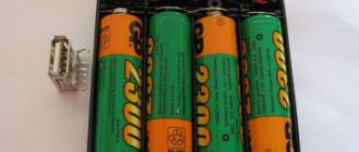
Acquaintance
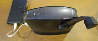
First, let's look a little at the appearance of our hero:
It's really very small! According to the smart book by Petrenko S.F. “Piezoelectric motors in instrument making”, it is in principle impossible to create smaller electromagnetic motors... that is, it is possible, but with a decrease in the diameter of the wire from which the windings are made, more and more energy is dissipated in the form of heat into the environment, which leads to a decrease in the efficiency of the motor and makes their use is irrational.
Of note, it can be noted that its shaft is very short and has a special groove for installing a gear or lever.
Two windings are clearly visible, which are even covered with insulation of different colors. This means that our motor most likely belongs to the class of bipolar stepper motors
. Let's see how it works:
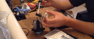
I believe that our acquaintance with these motors will not be complete if we do not look at what is inside it. It's always interesting to look inside the mechanism! Is not it so?
Actually, we didn’t see anything unusual. The rotor is magnetized. There are no bearings anywhere, everything is on bushings. The rear bushing is pressed into the engine housing. The front one is not secured by anything. Interestingly, the engine housing was assembled by spot welding. So the front cover of the case had to be cut down.
Now let's move on to the issue of connection and its electrical characteristics.
Let's make sure it's bipolar by ringing the windings. Really bipolar, just like in the picture above. Winding resistance is about 26 Ohm
, although the seller indicated 14 Ohm.
The description says that the supply voltage is 5V
. Although you and I know that for a stepper motor the current that its windings will consume is important. Let's try to connect.
What are stepper motors: let's look at their varieties
The operating modes of the motor determine 2 characteristics: the step size and the force applied to move. You can vary them by changing the connection method, the structure of the windings or shaft.
Accordingly, the classification of drives is carried out according to the following parameters:
- Regarding the design of the rotor, its structure plays a key role, since the specifics of interaction with the electromagnetic field of the stator depend on it. There are 3 options, and we will consider each of them below, with all the features, pros and cons.
- By type (number of windings) - as their number increases, the rotation becomes smoother, but at the same time the cost of the power unit increases, although the torque remains unchanged. They can be uni- and bipolar, in the first case they are connected with a branch from the midpoint, in the second - through 4 outputs.
Now let's pay attention to the structure of the shaft.
Variable reluctance stepper drives
As the name suggests, it does not have its own source of a constant field; In addition, its rotor is made of soft magnetic material and has a toothed shape. Through the contact areas closest to the stator, closure occurs - with attraction to the poles, providing discrete movements. In its design, it is similar to a gear, in which the rotational force appears due to opposing pairs and alternating current flow.
The key advantage is that there is no stopping moment, because the field, which in other cases can influence the reinforcement, is simply absent. You get a synchronous power unit in which the rotor and stator turn simultaneously and in unison.
Having the same dimensions as other varieties, these models develop less torque. The movement is carried out by 5-15 degrees, and this is relatively rough and often inaccurate. This explains the somewhat limited scope of application of a reactive stepper motor: where a motor of this type is used, it is in specific machines, all the parts of which are manufactured by the manufacturer independently.
With permanent magnets
Again, it is immediately clear what their peculiarity is - the presence of their own source of a constant field, which is
the basis of a moving element and containing 2 or more poles. It is the latter that ensure rotation of the rotor by applying voltage to the windings and attraction/repulsion.
The movement can be carried out either completely perpendicular to the previous position, or halfway; By increasing the number of magnetic pairs, you can adjust the length, and therefore the number of discrete movements, bringing their total number to 48 per full revolution. This allows you to very accurately install the working tool in the right place and is a competitive advantage of the power unit.
Hybrid
The design of this type of stepper motor was developed to combine the advantages of the previous two. It is a cylindrical field source, magnetized longitudinally, that is, a pair of poles with special surfaces - with applied teeth. The latter provide excellent retention without reducing torque.
Practical advantages:
- small step - 0.9-50 - which allows precision positioning due to a large number of discrete movements (up to 400 per cycle);
- high speed and smooth operation.
Yes, they are more expensive than the two previous types, since they are more difficult to manufacture, but this is a relative minus. Due to their advantages, these are the most common options today, used in the most critical cases: installed in CNC machines, in modern robotics devices, on medical and office equipment.
Closed and open-loop systems
Axis positioning systems allow intelligent controllers to position equipment with exceptional accuracy. A command is issued to move to the desired point in three-dimensional space and the machine responds very quickly and accurately.
Positioning systems typically use one of two methods: closed-loop and open-loop systems. So what is the difference between these two approaches to positioning?
Closed-loop systems typically use servo motors to control the speed and position of a moving axis. Servo motors work just like any regular motor, when power is applied to them they rotate. This rotation takes on a continuous smooth motion. The job of a servo motor is not only to drive the motor, but also to precisely control the speed.
Along with speed, position feedback is also required in a closed-loop system. This is usually provided by an encoder or linear scale. Positional feedback to the machine's controller allows it to move quickly to a target location and then smoothly slow down to settle on the target.
Open loop systems do not have a feedback device to control speed or position. Instead, the distance to be covered from the current location is divided by the machine control system into several precise steps of a certain size. The control system also determines the optimal system speed curve based on predefined parameters. The commands are then sent to the stepper motor in the form of pulses. The job of a stepper motor driver is to convert command pulses into actual motor drive steps, then the stepper motors advance through these steps to achieve the desired result.
Principles of use
Wind turbulence in the surface layers, characteristic of the Russian climate, leads to constant changes in its direction and intensity. Large wind generators with a power exceeding 1 kW will be inertial. As a result, they will not have time to fully unwind when the wind direction changes. This is also hampered by the moment of inertia in the plane of rotation. When a side wind acts on an operating wind turbine, it experiences enormous loads, which can lead to its rapid failure.
It is advisable to use a low-power wind generator, made by yourself, which has insignificant inertia. With their help, you can charge low-power mobile phone batteries or use them to illuminate your dacha with LEDs.
In the future, it is better to focus on consumers that do not require conversion of the generated energy, for example, for heating water. A few tens of watts of energy may well be enough to maintain the temperature of hot water or to additionally heat the heating system so that it does not freeze in winter.
What drivers for 3D printer stepper motors can you buy?
1. TMC2208, TMC2130, TMC2100. Output current per winding with additional cooling is up to 2 A, peak output current 2.5 A. Power supply voltage: 4.75 - 36 V. Step crushing: 1/2, 1/4, ⅛ and 1/16 with the possibility of interpolation up to 1/256. It is used to reduce noise when working with 8-bit microcontrollers. It can be used in devices with low-power operating modes, as well as in equipment where high energy efficiency of motors is in demand. The TMC2208 is built on a chip from Trinamic and is capable of delivering up to 2.5 A per winding, which is enough for use in 3D printers and CNC. At the same time, the problem of noisy operation of stepper motors is solved due to effective algorithms for generating control pulses (StealthChop2™) and current control.
Quiet drivers, we recommend installing them. It costs more than the others, about $15.
2. A4988 Permissible output current per winding with additional cooling - up to 2 A, without cooling - up to 1 A. Power supply voltage: 8-35 V. Advantages of the A4988 driver - the presence of protection against overloads and overheating, the ability to adjust the current and several options microstepping. Step crushing: 1, 1/2, 1/4, 1/8, 1/16. 9V is significantly quieter than 12V, without loss of torque. A sharp increase in sound occurs from 11V to 12V. Cost about 6 $.
We recommend reading: Cement resistors: what they are and in what cases they are used
4. DRV8825 Permissible output current per winding with additional cooling – up to 2 A. Power supply voltage: 8-45 V. Electrical and mechanical compatibility with the A4988 driver. Step crushing: 1, 1/2, 1/4, 1/8, 1/16, 1/32. According to reviews, they have a design flaw that results in the appearance of defects on the surface of the print in the form of vertical stripes (zebra stripes). The disadvantage can be eliminated by installing TL-Smoother, but it will be much more cost-effective to buy TMC2208 instead. Cost about 6 $.
Electrical part
As a generator, you can install a stepper motor (SM) for a printer in a windmill.
Even at a low rotation speed, it produces about 3 watts of power. The voltage can rise above 12 V, which makes it possible to charge a small battery. Other generators operate effectively at a rotation speed of more than 1000 rpm, but they will not be suitable since the windmill rotates at a speed of 200-300 rpm. A gearbox is needed here, but it creates additional resistance and also has a high cost.
In generator mode, the stepper motor produces alternating current, which can easily be converted to direct current using a pair of diode bridges and capacitors. The circuit is easy to assemble with your own hands.
By installing a stabilizer behind the bridges, we obtain a constant output voltage. For visual control, you can also connect an LED. To reduce voltage losses, Schottky diodes are used to rectify it.
In the future, it will be possible to create a wind turbine with a more powerful motor. Such a wind generator will have a high starting torque. The problem can be eliminated by disconnecting the load during start-up and at low speeds.
Smoothing device TL-Smoother
A board that connects the stepper driver and stepper motor, reducing noise and vibration in your 3D printer, reducing the risk of zebra stripe defects.
This small board has eight rectifier diodes that improve the stepper motor waveform, particularly for older, cheaper stepper drivers such as the DRV8825 and A4988. Improving the waveform reduces engine noise by reducing vibration. Since vibrations are reduced, print quality also improves. Just install the board between the driver and the stepper motor, the orientation doesn't matter. For convenience, the kit includes a small 4-wire connector, 20 cm long, to connect the board to the electronics. Cost about 7 $
Zebra stripe or moire defect
Connecting stepper motors
The choice of stepper motor connection diagram depends on:
- number of wires in the drive;
- way to start the mechanism.
Existing engine models have 4, 5, 6 or 8 wires. A device with four wires can only be connected to bipolar devices. It is equipped with two phase windings, each of which has two wires. To connect the driver step by step, you need to identify pairs of wires with a continuous connection using a meter.
In a six-wire mechanism, each winding has two wires and a central tap. The engines of this model are characterized by high power and are connected to both bipolar and unipolar actuators.
In the first case, one center tap of each winding and one end of the wire are used.
In the second case, all six wires are used. The separation of the wire is carried out using a measuring device.
The difference between a five-wire motor and a six-wire model is that the center terminal connection is a solid cable that goes to the center wire.
Since separating one winding from another without breaking is not possible, it is necessary to determine the center of the wire, and then connect it to other conductors. This will be the safest and most effective solution. Then the engine is connected to the network and its functionality is checked.
To successfully operate the mechanism, you need to keep in mind the following nuances:
- The rated voltage is produced by the primary winding at constant current.
- The change in initial torque speed is directly proportional to the change in current.
- The rate at which linear torque decreases at subsequent high speeds depends on the inductance of the windings and the drive circuit.
Typical SD connection diagrams
Connection diagram of a 6-pin stepper motor to the GeckoDrive driver (bipolar serial connection of windings)
Connection diagram for an 8-pin stepper motor with bipolar parallel connection of windings to the GeckoDrive driver
Connection diagram for an 8-pin stepper motor with a bipolar serial connection of windings to the GeckoDrive driver
Stepper motor control
There are three stepper motor control modes:
• full step
• half-step
• microstepping.
Full step control mode
The first method was described in the examples above. This is alternating phase switching, the phases do not overlap, at any time only one phase is connected to the voltage source.
The method is called in English one phase on full step - one phase per full step. The rotor balance points coincide with the stator poles. The disadvantage of this mode is that at the same moment half of the windings are used for a bipolar motor, and only a quarter for a unipolar one.
There is a variant of a full-step control mode in which two phases are turned on at the same time. It's called two-phase-on full step - two phases per full step. With this method, the rotor is fixed between the stator poles by supplying power to all windings.
half-step mode
This allows you to increase engine torque by 40%. The pitch angle does not change, the rotor is simply shifted by half a step in equilibrium. This method allows you to get twice as many steps from the engine per rotor revolution.
Every second step one phase is turned on, and between them two phases are turned on at once.
As a result of such commutation, the angular movement of the step is reduced by half, or the number of steps is doubled. It is not possible to obtain full torque in half-step mode.
Despite this, the half-step mode is often used. Using very simple methods, it doubles the number of engine steps.
It must be remembered that for both modes it is true that when the engine is stopped and voltage is removed from all phases, the engine rotor is in a free state and can move due to mechanical influences.
microstepping mode
To fix the position of the rotor, it is necessary to generate a holding current in the motor windings. This current can be significantly less than the rated current.
The ability of the stepper motor to fix its position when stopping allows you to do without mechanical clamps, braking systems, etc.
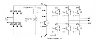
Control of brushless motors
A controller is required to control a stepper motor. The controller is a circuit that supplies voltage to one of the stator coils. The controller is made on the basis of an integrated circuit of the ULN 2003 type, which includes a set of composite keys. Each switch has protective diodes at the output, which allow you to connect inductive loads without requiring additional protection.
An H-bridge system is used to control brushless motors. Which allows you to switch the polarity to reverse the stepper motor. It can be performed on transistors or microcircuits that create a logical chain for moving keys.
As you can see, voltage is supplied to the bridge from the power source V. When contacts S1 – S4 or S3 – S2 are connected in pairs, current will flow through the motor windings. Which will cause rotation in one direction or another.
With controller
The controller device allows you to control the stepper motor in various modes. The controller is based on an electronic unit that generates groups of signals and their sequence sent to the stator coils.
To prevent the possibility of damage in the event of a short circuit or other emergency situation on the motor itself, each terminal is protected by a diode, which will not allow a pulse to pass in the opposite direction.
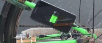
Wind power generator from an old scanner
Lately there has been a lot of talk about energy-saving technologies. These include thermal batteries, eternal light bulbs, solar panels, and even the use of manure as a source of alternative energy and other agricultural waste.
It turns out that as an option you can get free electricity from the engine of an unnecessary scanner. We will talk about how to make a wind generator from a stepper motor in this article.
Here, the most interesting thing is the method of manufacturing the blades. Below are instructions that will help you recycle your old scanner into an impressive electricity generator.
We will need:
- Old scanner;
- Rectifying diodes (8 1N4007 diodes were used in the project);
- Capacitor 1000 uF;
- Stabilizer LM7805;
- PVC pipe;
- Plastic parts (see below);
- Aluminum plates (any others can be used).
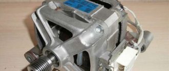
In addition to the fluorescent tube and electronic components, the scanner has a stepper motor, which is exactly what we need. The photo shows a four-phase stepper motor.
Now that we have all the necessary components, we can begin assembling the rectifier.
For each phase we need 2 diodes, i.e. only 8 diodes. The output voltage will be strictly stabilized using the LM7805 IC and a 1000 uF capacitor.
For USB charging, two 15 kOhm resistors are required on both data buses. For technical details, see the USB bus specification.
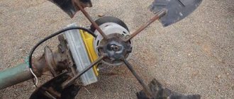
We collect the blades.
This is all!
Now all that remains is to wait for a windy day and test the device, as can be seen in the photo - the device stably generates a voltage of 4.95 V.
Thus, you can now charge your MP3 player or phone completely free of charge.
DIY stepper motor controller
The task is simple: using the ready-made circuit and program of Pavel Bakhtinov from this forum, lay out a printed circuit board, assemble and debug a controller for controlling stepper motors installed in the mount of an astronomical telescope. Next, you need to make a decent case and control panel. It all starts with the details (Murphy’s law immediately comes to mind: “No talent could survive the passion for details”):
Working on the diagram:
We lay out the printed circuit board:
The photo template is ready:
Here I need to say a few words about my KNOW-HOW in making photo masks for transferring a design onto a printed circuit board.
Usually I print them on a printer - often on an inkjet, less often on a laser, because... The thermal film shrinks unexpectedly after heat treatment in the laser (and templates are needed for both sides), so it was impossible to align the two templates with sufficient accuracy (up to 0.15 mm).
The inkjet printer reproduces the dimensions well, but does not fill the paths with black densely enough; in some places they are still visible. A solution to this problem was soon found: we print not with pure black, but a little lighter towards yellow - the printer begins to add yellow (opaque to UV radiation) and tracks to the black ink, although they look more transparent, after photo transfer they turn out denser, practically without Izyanov.
We recommend reading: What is a zener diode used for and how does it work?
The main thing is to choose the exposure:
The process of etching the printed circuit board is in progress:
Fully etched:
We drill holes with a diameter of 0.7mm to 1.5mm using a homemade drilling machine:
The soldering iron is old and remote:
We stuff the board with details:
All parts are sealed:
The reverse side of the board, the debugging process has begun:
This is how we will place the heating elements (those above in the figure on this side of the board are an integrated stabilizer and two microcircuits - motor drivers) on such beautiful radiators:
At this time, work has begun on the remote control. The main thing in the control panel, I think, is ergonomics, as far as it is appropriate to apply this to the box that will be obtained after assembly on domestic LARGE but reliable microbuttons.
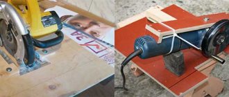
Materials and tools for making a CNC machine from a printer
A simple homemade CNC machine from a printer is shown in the photo. It has a working area measuring 16 × 24 × 7 cm. It is capable of processing textolite (up to 3 mm thick), plywood (up to 15 mm), plastic and wood. The main purpose is engraving.
To manufacture such a machine, you will need the following materials, parts and components:
You should prepare the following tool in advance:
For measurements and markings you will need a metal ruler and a square.
What useful things can you get from a printer?
From a matrix printer you can take many parts to assemble a CNC machine:
Important! The device should be disassembled as completely as possible. Almost all the parts are useful for assembling the machine - screws, nuts, studs, etc.
SD controllers
Controllers are switching boards used to convert control commands coming from a PC into a sequence of pulses for drivers. The board may have additional functionality - connectors for connecting limit stops, power relays, connectors for spindle control. Connects to a computer via LPT or USB interface.
Multichannel SD drivers are a device that combines SD drivers and a switching board. They connect to a PC and directly control the SD. The controller also includes such functionality as a coolant timer, a PWM converter for the inverter, power relays, connectors for connecting linear movement limitation sensors. Drivers can be executed for different numbers of SDs.
Advantages and disadvantages of a stepper motor
The advantages of using a stepper motor include:
- In stepper motors, the angle of rotation corresponds to the number of electrical signals supplied, while after stopping the rotation, the full torque and fixation are maintained;
- Precise positioning – provides 3 – 5% of the set step, which does not accumulate from step to step;
- Provides high speed start, reverse, stop;
- It is highly reliable due to the absence of rubbing components for current collection, unlike commutator motors;
- The stepper motor does not require feedback to position;
- Can produce low speeds for a directly applied load without any gearboxes;
- Relatively lower cost compared to the same servos;
- A wide range of shaft speed control is provided by changing the frequency of electrical pulses.
The disadvantages of using a stepper motor include:
- A resonance effect and slippage of the stepper unit may occur;
- There is a possibility of loss of control due to lack of feedback;
- The amount of electricity consumed does not depend on the presence or absence of a load;
- Difficulty in control due to the design of the circuit
How to connect a stepper motor without a controller
Stepper motors are found in cars, printers, computers, washing machines, electric shavers and many other everyday devices. However, many radio amateurs still do not know how to make such a motor work and what it actually is. So let's learn how to use a stepper motor. Stepper motors are part of a class of motors known as brushless motors. The stepper motor windings are part of the stator. The rotor contains a permanent magnet or, for cases with variable magnetic resistance, a gear block made of soft magnetic material. All switching is carried out by external circuits. Typically, the motor-controller system is designed so that it is possible to move the rotor to any fixed position, that is, the system is controlled by position. The cyclical positioning of the rotor depends on its geometry.
Creation of a wind generator
Creating a wind generator does not necessarily mean creating a large and powerful complex capable of providing electricity to an entire house or a group of consumers. It is possible to make a small windmill, which is, in fact, a working model of a serious installation. The purpose of such an event could be:
- Introduction to the basics of wind energy.
- Joint learning activities with children.
- An experimental sample prior to the construction of a large installation.
Creating such a windmill will not require the use of a large number of materials or tools; you can make do with improvised means. You can’t count on generating significant amounts of energy, but it may be enough to power a small LED lamp. The main problem that exists when creating small wind turbines is the generator. It is difficult to create it yourself, since the dimensions of the device are small. The easiest way is to use a small electric motor, allowing it to be used as a generator.