Do-it-yourself frequency generator for a three-phase electric motor
Today, asynchronous motors are the main traction drives for machine tools, conveyors, and other industrial units. In order for motors to function normally, they need a frequency converter. It allows you to optimize the operation of the unit and extend its service life. It is not necessary to buy a device - you can make a frequency switch for a three-phase electric motor yourself.
- Purpose of the frequency converter
- How the device works
- Making your own device Making a three-phase converter
- Frequency converter for single-phase motor
- Possible problems during verification
Recommendations for equipment maintenance
In order for a self-assembled frequency converter to successfully perform its functions for a long time, the owner must follow the following recommendations:
- Monitor the condition of the internal elements, preventing dust from accumulating on them. If necessary, use a small compressor, since a vacuum cleaner may not be able to remove dust that lies in a dense layer.
- Check the functionality of the components and change them if necessary. The normal service life for electrolytic capacitors is 5 years, for fuses - 10 years. Cooling fans should be replaced after 2-3 years of operation. Internal cables can be used for no more than 6 years.
- It is necessary to monitor the temperature of the internal mechanisms, as well as the voltage on the DC bus. If the temperature rises, there is a danger of the thermal conductive paste drying out, which can result in the failure of the capacitors. It is necessary to make it a rule to apply a new layer of paste to the power drive components at least every three years.
- The operating conditions must be strictly observed. The optimal ambient temperature is considered to be up to + 40 degrees. Increased humidity and dust in the air have an extremely negative impact on the operation of the elements.
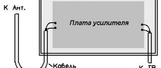
Functional diagram for connecting a frequency converter
When using it, it is possible to produce a fairly good sinusoidal PWM with the ability to change the voltage. We turn the motor wheel of the stroller by hand and press the “Start” button. You can make copies of the contents of this folder in the parent folder, rename it and files of the same name with the extensions ewp, ewd, dep.
Conventional variable voltage intermediate circuit current inverter.
The method of limitation depends on the type of modulation. As well as the timer interrupt handling function.
As well as the timer interrupt handling function.
They provide a wide frequency adjustment range, have high efficiency and other excellent technical characteristics. To the right of the bridge are operational amplifiers that normalize the signals of the current sensors.
The advantage of controlled rectifiers is their ability to return energy to the supply network. There are three main options for setting switching modes in an inverter controlled by pulse width modulation.
In this case, the amplitude and frequency of the voltage at the output of the converter are regulated by slip and load current, but without using feedback on the rotor rotation speed. CONNECTING A FREQUENCY CONDITIONER to a single-phase asynchronous motor.
Below is a diagram of the frequency converter.
It consists of 3 transforming links:
- a rectifier that generates DC voltage when connected to the power supply network, which can be controlled or uncontrolled,
- a filter that smoothes the already rectified voltage (capacitors are used for this),
- an inverter that generates the required voltage frequency, which is the last link before the electric motor.
Control Modes
Frequency generators are distinguished by types of control:
- scalar type (no feedback),
- vector type (presence of feedback, or its absence).
In the first mode, the stator magnetic field is subject to control. In the case of vector control mode, the interaction of the magnetic fields of the rotor and stator is taken into account, and the rotation torque is optimized when operating at different speeds. This is the main difference between the two modes.
In addition, the vector method is more accurate and efficient. However, it is more expensive to maintain. It is designed for specialists with a wealth of knowledge and skills. The scalar method is simpler. It is applicable where the output parameters do not require precise adjustment.
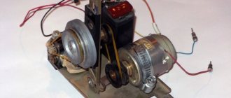
DIY frequency converter
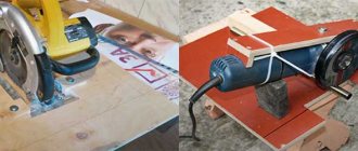
DIY frequency converter - I present to you a short article about an asynchronous motor and a frequency converter, which I previously had to make. So now I needed a good drive for a circular saw. Of course, it would be possible to buy a branded frequency generator from a store, but still, the option of making it yourself turned out to be the most acceptable for me.
In addition, the quality of speed control of the sawmill drive did not require absolute accuracy. However, it must cope with impact loads and long-term overloads. In addition, I wanted to make the control as simple as possible, without any parameters, but just install a couple of buttons.
The main advantages of variable frequency drive:
- We create from a single-phase voltage 220v full three phases 220v, the shift of which will be 120°, and we obtain absolute torque with power on the shaft
- Increased starting torque with soft start without maximum starting current
- There is no strong magnetization and excessive overheating of the motor, as happens when capacitors are used
- If necessary, you can freely control the rotation speed and change direction
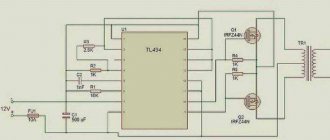
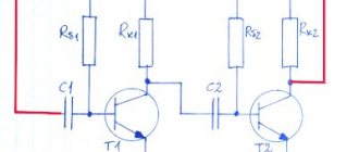
Below is a schematic diagram of the device:
The three-phase bridge is made on hybrid IGBT transistors with reverse conduction diodes. In general, this represents bootstrap control of the PIC16F628A microcontroller, carried out using specialized HCPL-3120 optodrivers. A voltage suppression capacitor is installed in the input path, which performs the function of soft charging of electrolytic capacitors in a constant voltage circuit.
Purpose and principle of operation of the inverter
The inverter controls the rotation speed of asynchronous electric motors, i.e. motors that convert electrical energy into mechanical energy.
The resulting rotation by the drive devices is transformed into another type of movement. This is very convenient and thanks to this, asynchronous electric motors have gained great popularity in all areas of human life. It is important to note that the rotation speed can be adjusted by other devices, but they all have many disadvantages:
- difficulty to use,
- high price
- low quality of work,
- insufficient control range.
Many people know that using frequency converters to regulate speed is the most effective method. This device provides smooth start and stop, and also monitors all processes that occur in the engine. The risk of emergency situations when using a frequency converter is extremely insignificant.
To ensure smooth adjustment and speed, a special frequency converter circuit has been developed. Its use significantly increases the continuous operation time of a three-phase motor and saves energy. The converter allows you to increase the efficiency to 98%. This is achieved by increasing the switching frequency. Mechanical regulators are not capable of this.
Connecting the frequency converter
If the wiring used has one phase and a voltage of 220V, then the “triangle” option is used as the preferred connection diagram. It is important to remember that the output current can be no more than 50% greater than the rated current. If we are talking about three-phase wiring with a voltage of 380V , then a “star” circuit is selected to connect the frequency converter to the motor. To make this procedure easier, there are terminals on the converter, on the surface of which there are hints in the form of letters.
- R, S, T – network wires are connected to these contacts in any order;
- U, V, W - with their help, the asynchronous motor is switched on (in cases where the motor operates in reverse mode, to return to normal rotation, it is enough to swap any of the two wires on the contacts).
The design must have a terminal used for grounding.
How to choose a regulator
There are several characteristics by which you need to choose a speed controller for a car, machine electric motor, or household needs:
- Control type. For commutator motors, there are regulators with a vector or scalar control system. The former are more often used, but the latter are considered more reliable;
- Power. This is one of the most important factors for choosing an electrical frequency converter. It is necessary to select a frequency generator with a power that corresponds to the maximum permissible on the protected device. But for a low-voltage motor it is better to choose a regulator more powerful than the permissible watt value;
- Voltage. Naturally, everything here is individual, but if possible, you need to buy a speed controller for an electric motor, the circuit diagram of which has a wide range of permissible voltages;
- Frequency range. Frequency conversion is the main task of this device, so try to choose a model that will best suit your needs. Let's say, for a manual router, 1000 Hertz will be enough;
- According to other characteristics. This is the warranty period, the number of inputs, the size (there is a special attachment for desktop machines and hand tools).
Devices from the Sinus, E-Sky and Pic brands have proven themselves well.
At the same time, you also need to understand that there is a so-called universal rotation regulator. This is a frequency converter for brushless motors.
Photo - regulator diagram for brushless motors
There are two parts in this circuit - one is logical, where the microcontroller is located on the chip, and the second is power. Basically, such an electrical circuit is used for a powerful electric motor.
Video: electric motor speed controller with SHIRO V2
What does the control drive consist of?
It consists of three parts:
- a rectifier that provides a direct current potential when connected to the electrical network. The network may or may not be managed;
- a filter element that smoothes the output voltage (capacitance is used);
- an inverter that produces the desired frequency potential, the outermost link near the electric motor.
How to make a homemade engine speed controller
You can make a simple triac motor speed controller, its diagram is presented below, and the price consists only of parts sold in any electrical store.
To work, we need a powerful triac of the BT138-600 type, it is recommended by a radio engineering magazine.
Photo - do-it-yourself speed controller diagram
In the described circuit, the speed will be adjusted using potentiometer P1. Parameter P1 determines the phase of the incoming pulse signal, which in turn opens the triac. This scheme can be used both in field farming and at home. You can use this regulator for sewing machines, fans, tabletop drilling machines.
The principle of operation is simple: at the moment when the motor slows down a little, its inductance drops, and this increases the voltage in R2-P1 and C3, which in turn leads to a longer opening of the triac.
A thyristor feedback regulator works a little differently. It provides energy back into the energy system, which is very economical and profitable. This electronic device involves the inclusion of a powerful thyristor in the electrical circuit. His diagram looks like this:
Here, to supply direct current and rectify, a control signal generator, an amplifier, a thyristor, and a speed stabilization circuit are required.
Source: www.asutpp.ru
Setting up the frequency converter
When setting up the frequency generator, you need to pay attention to the following points:
- If possible, limit the acceleration and deceleration times in order to reduce heating of the drive and the motor. The same applies to the number of on/off cycles per unit of time.
- Select scalar frequency control mode.
- Disable phase loss monitoring at the inverter output.
- Before the first start-up, be sure to carry out automatic configuration (adaptation) according to the instructions.
Here you need to pay attention to one important point. A single-phase motor has lower efficiency than a three-phase motor with the same parameters. This should be taken into account when choosing a drive/motor pair. To increase efficiency and reduce heating, you can experimentally set points on the voltage-frequency graph. Alternatively, you can disconnect the starting capacitor, and connect the leads from the starting and working windings to the output of the three-phase converter. Next, carry out the settings as indicated above.
Using modern inverters
Modern converters are manufactured using microcontrollers. This has greatly expanded the functionality of inverters in the field of control algorithms and monitoring of operational safety.
Converters are used with great success in the following areas:
- in water supply and heat supply systems to regulate the speed of hot and cold water pumps,
- in mechanical engineering,
- in the textile industry,
- in the fuel and energy field,
- for borehole and sewage pumps,
- for automation of process control systems.
The prices of uninterruptible power supplies directly depend on the presence of a frequency converter in it. They become “guides” to the future. Thanks to them, small-scale energy will become the most developed sector of the economy.
Heat exchange of system elements
Particular attention should be paid to heat dissipation. The more powerful the device being developed, the more reliable the cooling system should be. As mentioned above, the base should be made of aluminum. The voltage converter circuit must provide protection against overheating. For this purpose, you need to drill a hole in the housing and install a temperature sensor in it. The signal from it is sent through a matching device to the microcontroller. If the maximum temperature is exceeded, the load must be switched off. Consequently, the power transistor module is turned off.
To improve heat transfer, it is necessary to use fans. Their location must be chosen so that the air flow cools the fins of the housing radiator. To increase the efficiency of the cooling system, it is necessary to use thermal paste. It is wiser to turn on the fans when the device is started. But you can also program the controller using the signal from the temperature sensor. When the temperature reaches half the temperature at which the device shuts down, the fans turn on.
The second method is phase shift
This option for obtaining three-phase voltage is based on the properties of inductance (the current lags behind the network voltage by a conventional 90-degree angle between the vectors) and capacitance (the voltage leads the current in the electrical circuit by a conventional 90-degree angle between the vectors). By combining inductive and capacitive elements with the load, with their specific combination, a phase shift of 120 degrees in voltage is obtained in the special circuit shown below. Each power value will require elements of corresponding size. They are shown in table No. 1.
Scheme
Table No. 1 for obtaining three-phase voltage on an active load
For an asynchronous engine, in which the equivalent of the stator windings are resistances and capacitances connected in parallel, the circuit and values of the elements will be different. They are given below in table No. 2 along with the diagram.
Scheme
Table No. 2 for obtaining three-phase voltage on the windings of an asynchronous motor with a squirrel-cage rotor
The circuit requires metal-paper capacitors with a rated voltage of 250 V or more. For inductors, it is recommended to use a core from a 200 VA transformer. The number of turns is selected based on the measured current in an electrical circuit consisting of an inductor and a resistor with a known resistance connected in series. This circuit, together with a multimeter, is connected to a 100…300 Hz generator. Additionally, the inductance value is adjusted by the air gap in the core. Its presence is mandatory.
Previously, according to the parameters of the generator, the current strength is calculated for the section of the circuit according to Ohm’s law.
An increase in inductance will result in a decrease in current, and vice versa. The coincidence of the measured value with the calculated value indicates that the inductance of the required value has been obtained. This method is only suitable for a static load on the shaft of an asynchronous motor. If there are deviations, the phase characteristics of the voltage in the windings will change along with the torque. That is, the engine efficiency will deteriorate.
Design features
The converter includes a protective system that prevents possible overload due to short circuit currents and voltage surges, and protects against overheating. The developed inverter models from 220 to 380 provide a smooth start of the engine, ensuring an increase in voltage at the start while maintaining a constant value of its ratio with the phase current.
The weight and volume of the inverter allow it to be transported, but such a device is not cheap. In this regard, purchasing an inverter when three-phase electrical appliances are rarely used is considered inappropriate.
Advanced models offer a set of additional options, such as:
- a set of extension cables and cables;
- remote controls;
- sensors of technological parameters;
- braking resistors and choppers;
- input and output filters; interface boards and modules, etc.
Replacement options
It is also possible to obtain a 380 V voltage source through the use of three phases from electrical power sources with a voltage of 220 V, however, in high-rise buildings this is recommended only with the consent of the energy supervision company. If it is possible to connect electrical equipment to a three-phase distribution panel, which is usually located in the entrance, a voltage converter is not needed - a three-phase extension cord is sufficient
Existing methods of converting single-phase current into three-phase, although effective, have some disadvantages:
- frequent loss of engine power;
- impossibility of obtaining three-phase current without interference;
- power limitations of frequency converters;
- the presence of types of electric motors that cannot be started using similar methods in a single-phase network;
- Power capacitors are not very convenient to use, since the system turns out to be large and poses a danger to the room.
It is possible to make such a device at home, but it is quite problematic and labor-intensive, so buying an inverter will be a much simpler and safer decision, given the wide selection of products in this segment.