You can be sure that your young operator will love lifting heavy loads with this wooden machine.
Before your little one gets lost in video games, give them an imaginative gift like this powerful crane.
- Dimensions: height - 635 mm; boom radius - 345 mm; track - 197 mm; wheelbase - 289 mm.
- A hand winch raises and lowers the boom and bucket.
- Thanks to the swivel support, the tower structure rotates smoothly to move the load.
- The wide chassis with eight twin wheels provides stability and mobility on the construction site. (If you have a lathe, you can quickly turn out the number of wheels you need. Ready-made wooden wheels can be purchased at hobby and craft stores.)
- You will need a small amount of straight scraps and a few screws. Other little things will also probably be found in your workshop.
MASTERING THE SKILL
- Learn how to secure round pieces to a drill press table.
Make a chassis
Mark the centers of the holes for the wheel axles in chassis A. Using a clamp, pressing the chassis against the drill table stop, alternately drill holes 38 mm deep.
1. For chassis A , cabin G and counterweight H , cut a blank measuring 38x159x305 mm. (We chose walnut.) Using a longitudinal cut, separate a 38 mm wide block from one edge of the workpiece and set it aside to later make a cabin and counterweight out of it. Saw the rest of the workpiece to the dimensions of chassis A, indicated in the “List of Materials”.
2. Mark the front and rear bevels A (Fig. 1). File them with a band saw and sand them smooth. Then insert a 9 mm drill bit into the drill chuck, fix the stop at a distance of 13 mm from the drilling axis and make holes for the wheel axles on both sides of the chassis (photo A) . Finish sand the part.
Decorative use
A decorative faucet for the garden is an element of the design of the garden area. It performs its decorative function in combination with wall-mounted drinking fountains, columns or hydrants made in retro style. An appropriately designed detail emphasizes the intended style, be it classic, baroque or minimalism.
In Italian style Source thespaandfitnessclub.com
Glue the mast and boom
Fasten the side parts B with double-sided tape, mark the centers and drill holes through both parts.
1. For side parts B and gaps C , cut out two blanks measuring 19x38x660 mm. (We used maple.) From each piece, make one side piece and one spacer. Attach a Forstner drill with a diameter of 25 mm to the drilling station chuck and make five holes in each side part (Fig. 2, photo B)
2. To assemble the mast, prepare a pair of clamping strips measuring 19x57x610 mm. (We used scrap MDF.) Cover one side of the clamping strips with masking tape to prevent them from sticking to the parts. Place tape on one side of each side piece B , limiting the locations of the spacers C in accordance with Fig. 2. (The tape is thick enough to keep the clamping bars from moving and to easily remove excess glue.) Glue the mast parts together (photos C and D ).
Glue spacers C to one side piece B. Apply glue and place the second mast side piece on top.
Secure the parts between the leveling bars and then press them vertically with clamps. The bottom spacer C and both side pieces B must be aligned at the base.
3. Mark the center of the 5 mm hole for the boom axis on (Fig. 2). Using a drill press, make a hole by inserting 19mm thick scraps between the mast side pieces to prevent chipping.
Once the glue has dried, remove the clamps and strips, mark a bevel on the top end of the mast and file it with a bandsaw.
4. Make an upper bevel B/C (Fig. 2, photo E) and sand it smooth. Then sand the 3mm fillets on the top corners of side pieces B and top spacer C . Insert an edge cutter into the collet of a router mounted in the table and mill 2 mm wide chamfers along the edges of the holes and the outer ribs of the mast (except for the bottom ones). Finish sand the mast.
5. To make the front D and rear E boom spacers, sharpen a workpiece measuring 35x560 mm to a thickness of 6 mm (we took walnut) and cut it into pieces of the specified length. Using a band saw, make a bevel on the front spacer and a taper on the back (Fig. 3). Sand the sawed edges.
As with the mast assembly, prepare 19x19x610mm clamping strips and apply masking tape to align spacers D, E between the side pieces F for gluing.
6. For the side parts of the F , take a maple blank measuring 19x35x5 72 mm, saw it along the thickness in two and plan both strips. Glue spacers D, E between the side parts F (Fig. 4 and photo F ).
7. Once the glue is dry, use a drill press to make a 2.5mm hole in the rear spacer E for the cord, a 5mm hole for the axle, and another 5mm hole at the front end of the boom (Figure 4). Before drilling the front hole, insert a 6mm thick piece of scrap F Then mark the two tapers, cut them with a band saw and sand them down to the marking lines. Also sand the 3mm rounds on the ends of the boom and rout 2mm chamfers along all the ribs. Finish sand the finished arrow.
Do-it-yourself crane beam in the garage: manufacturing advice
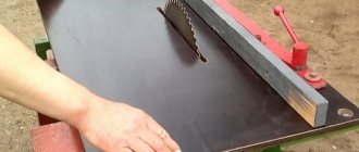
To make a beam crane yourself, you need to have some plumbing and welding skills. Only a garage with sufficient area is suitable for the location of the finished crane. To get started, you must first purchase a pipe with a rectangular cross-section, a metal corner, a metal C-profile and sliding wheels.
When installing posts and rails, it should be taken into account that the walls of the garage most often are not even.
The frame is welded from a corner along the entire width of the building. Particular attention should be paid to ensuring that all ribs are located strictly parallel and perpendicular. To make the trolley, a pipe with a rectangular cross-section is used. The frame must be placed on wheels, which must coincide with the ribs of the frame.
Making Tips:
- It is better to attach the rollers to a strip welded overlapping where the rods are connected to the supports.
- To make the crane movable, rollers are welded to the racks, which can be taken from containers used in warehouses.
- To manufacture the lifting mechanism, a manual worm winch equipped with a steel cable is used.
If there is no winch, it can be replaced with a hoist. But in this case, for the manufacture of the rod it is necessary to use a double tee. A crane beam, manufactured taking into account all the rules, will allow you to easily remove the engine and lift the car body.
Add a cab and counterweight
1. Take the previously set aside blank for cabin G and counterweight H. Mark the center of the hole in the middle of the width at one of its ends (Fig. 1a). Using a 25mm Forstner drill bit, make a hole using a drill press. Then use a band saw to cut a 10 mm wide bevel, sand it and saw off the cabin from the workpiece. Mill 2mm chamfers on the edges of the hole and the outer ribs of the cab. Finish sand the part.
Apply a little glue to the G cabin and glue it to the B/C mast close to the D/E/F boom, securing it with a clamp.
2. Before attaching the G to the B/C , insert a boom between the side parts of the B and a piece of threaded rod into the holes of both parts. Then glue the cabin to the side parts B (Fig. 1 and photo G ). Now temporarily remove the boom from the mast.
H to the specified dimensions . Mill chamfers on its edges (Fig. 1) and finally sand the part. Glue the counterweight to the D/E/F , aligning it in the middle of the width with a space of 13mm from the rear end.
Application area
In retail sales, this simple locking device is found under different names; you can see a watering, water tap or just a water tap. The device is widely used in gardens, gardens and private households in several predictable ways:
- In the country washbasin . Most washbasins have a simple design and are not heated, so there is no need to equip them with a mixer.
- For watering . Taps designed for watering, as well as filling and emptying containers, are equipped with a fitting (adapter) for connecting a hose. It can be stationary or threaded (removable).
- In a house (apartment). A simple and practical water tap is used as a flushing tap, pipeline vent (air valve on the heating riser or on the heating device). In older homes (and a tradition everywhere in Britain), separate taps successfully supply water to the sink.
Decorative country washbasins Source sovet-ingenera.com
- As a decorative element . A beautifully designed decorative garden faucet can become part of an original design idea (for example, as part of an original Italian-style water column). It features an aesthetic appearance, intricate finishing and a higher price.
Make a winch
I from 12 mm planks . Use double-sided tape to connect them face to face. Mark according to Fig. 5a the centers of the holes and drill them with a 6mm drill bit using a drill press. Mark a bevel on one corner, file it with a band saw and sand it. Then sand the small rounds on the outer corners, separate the pieces and give them a final sanding.
2. Cut out the winch platform J , making sure that its width matches the total thickness of the B/C mast and both sides I. Mill a chamfer along the top front rib (Fig. 5). Drill mounting holes to attach the base to the side parts of the mast B. (For screws with a diameter of 4.2 mm, the diameters of the mounting and pilot holes are 4 and 2.8 mm, respectively.)
Through the holes in the sides of winch I, drill 5mm holes for threaded rods through the B/C mast.
3. Using clamps, attach the side frames I to the platform J (Fig. 5). Drill holes and screw in screws. (For screws with a diameter of 3.5 mm, the diameters of the mounting and guide holes are 3.5 and 2.4 mm, respectively.) Insert the B/C between the sides of the winch and through their holes, drill holes in the side parts B of the mast. Screw in the screws. Now, using a drill press, make 5mm through holes in the mast (photo H).
Place the swivel support in the middle of chassis A, turn the winch and mast sideways to access the bottom flange and mark the centers of the screw holes.
4. Turning the winch over with the mast attached, place a swivel support in the middle of the lower side of the base J , drill guide holes and screw in the screws (Fig. 1). Then place the winch and mast on chassis A and mark the centers of the holes for attaching the swivel support (photo I). Remove the mast and winch from the chassis to drill holes for the screws.
5. Take two pieces of 6mm wooden dowel rod, 102mm long, and glue a spool in the middle of each (Figure 5). When the glue has dried, drill a through hole with a diameter of 2.5 mm in the middle in the coils and dowels.
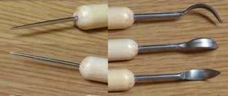
6. In four wooden button handles, drill an axial hole to a diameter of 6 mm to a depth of 10 mm. How to fix the handles on a drilling machine is described in the “Tip of the Master” below.
Master's advice
How to Safely Hold Round Pieces When Drilling
When trying to drill holes in turned knobs, you are faced with two difficulties: how to hold the spherical part upright on a level table and how to prevent it from rotating when the drill is immersed in the wood. There is an easy way to kill two birds with one stone. Drill a 19x6 mm recess in the cut board. Place a piece of double-sided tape measuring 38x38mm on top of it (photo below left). Align the handle over the center of the recess and press it firmly onto the trim. Now, pressing the scrap against the machine stop, position the drill exactly above the axial hole of the handle and you can start drilling (photo below right). This method also works for wooden balls.
Video description
About garden washbasins in the following video:
- Threaded valve axle (or screw axle). A system in which the water supply is regulated by turning the knob, and inside by a rubber shut-off gasket. The advantage of the design is its unpretentiousness, since it is able to work in contaminated water. The downside is the periodic wear of the gasket, which is why the device requires periodic maintenance.
- Metal-ceramic axle box . The water flow is controlled using polished metal-ceramic discs. Such shut-off valves have a long service life, but are sensitive to impurities in the water; It is preferable to install it in a system with a water purification filter.
Washbasin in a classic style Source love-calculator.me
Finishing and assembly
1. Remove the swivel support, mast B/C and side frames I from the winch platform J. Inspect all parts and, if necessary, sand them additionally. Place the wheels and tub on a 6mm rod and place thick scraps under the ends. To apply a finish to wooden axles without touching the ends that will be glued into the holes, take a piece of thick wood and drill eight 10mm holes in it and insert the axles into them. Then make six 6mm holes at least 50mm apart in the other trim. Insert short dowels into four of them and attach button handles to their ends. Wrap masking tape around one end of each spool pin and insert the other ends into the remaining trim holes. Apply a clear coat to all parts of the toy. (We used a semi-gloss spray varnish, which was applied four times, sanding in between with 320-grit sandpaper. The wheels were brushed with a soft brass wire brush after each coat had dried.)
2. Place a wheel and washer on each axle.
Glue the axles into the holes of the chassis A , inserting a thin plastic spacer between the wheel and the washer so that the wheels can rotate freely.
one of the side frames I to the winch platform (Fig. 5). Place a washer, a spring and another washer on each rod with a reel, and insert them into the holes in the side of the winch. Add two more washers with a spring to each rod and install the second side of the winch so that the rods with the reels are between the two side frames. Place one more washer on the ends of the rods protruding from the outside and attach the button handles, smearing their holes with glue.
4. Attach the B/C . Prepare two pieces of M6 threaded rod 92 mm long (10 mm larger than the width of the base) and pass them through the holes in the sidewalls I and the mast (Fig. 5). Apply a little special fixing paste to the ends of the studs and screw on the cap nuts. Attach the swivel support with screws to the winch platform J and then to the chassis A.
5. Now take two more pieces of threaded rod, 67 and 29 mm long. Insert the boom F /H between the side parts of the mast B. Insert a long piece of pin into the axial holes (Fig. 1). Apply locking paste and screw on the cap nuts. Insert a short piece into the holes at the front end of the boom and also secure it with cap nuts and apply locking paste.
6. Cut a cord 61 cm long and tie a knot at one end. Pass it from above through the hole in the rear boom spacer E , then through the hole in the rear spool and tie a second knot. Wind the excess cord onto the spool by rotating the knobs.
7. Cut a 183 cm long cord, thread it through the hole in the front spool and tie a knot. Then pass the cord into the gap between the front and rear boom spacers D, E , through the top mast spacer C and between the front spacer and the front threaded rod. Attach a weight hook to the end of the cord and wind the loose excess cord onto the spool. Finally, hang a small tub on a hook. Don't forget to put on your gloves and hard hat before turning on the engine and letting your imagination run wild!
Crane toy, 3.8 out of 5 based on 12 ratings
How to use
The telescopic boom of the mechanism can be installed in several positions. The goose is maneuverable and can be controlled by 1 person. The equipment lifts quite heavy loads due to the installed jack; no additional accessories or devices for moving heavy loads are needed.
In order to raise the car engine, you need to open the hood and roll up the crane. It is installed so that the “legs” are placed under the machine, and the chain with the hook hangs over the engine.
The engine has eyes, cables are hooked onto them, and a chain with a hook is connected to them. Having installed the pry bar, pump the jack. He raises the boom, and the engine goes up with it.
After the repair of the machine is completed, the motor is lowered into place and the hook is removed. The crane is rolled away from the car. If necessary, it can be disassembled.
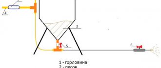
Lift for laying aerated concrete blocks
Abroad, during the construction of private houses, cranes and various lifts are often used. This way construction goes faster, which means the “box” is cheaper, because It is more profitable to use small-scale mechanization tools than to hire laborers. Our developer relies on himself and often builds a house “with one helmet.” Therefore, the urgent question is how not to physically overstrain yourself when laying a wall from aerated concrete blocks weighing 35-40 kg.
An interesting option is the unusual homemade “assistant” of the FORUMHOUSE user with the nickname Krestik. First, let's show what he took as a basis.
German mini crane with retractable central post
A special feature of the lift is the original folding “arm-boom”, with the help of which the crane, moving on wheels, can reach two opposite walls.
I am building a house myself and, in order to be able to lay aerated concrete blocks, I built a lift according to the above model. The crane was made completely collapsible, except for the base. I didn’t measure the maximum load on the hook, but it easily lifts me (weighing 95 kg).
Technical characteristics of the lift:
- width – 2200 mm;
- height – 4200 mm;
- boom radius – 4200 mm;
- load capacity of electric hoist – up to 800 kg;
- total weight of the crane with ballast is approximately 650 kg;
- lift weight without ballast – about 300 kg;
- The maximum lifting height of the masonry block is 3500 mm.
The working height of lifting blocks is adjustable in two ranges. The first is 1750 mm. The second is 3.5 m, for which the structure is raised, sliding upward along the supporting “legs” using a hydraulic jack lined with spacers made of GB blocks.
To make the lift, the user needed:
- swivel wheels;
- profile pipes for the mast, “legs” and boom with a section of 12x12 cm, 12x6 cm, wall 6 mm;
- pipe-jibs – 63x3 mm;
- powerful gate hinges;
- The boom rotating mechanism is made of ST45 steel and “205” bearings.
During operation, the design was modified. For example, the user laid the cable for the winch in a corrugated pipe and extended the cable for the control panel.
The design has a number of shortcomings that I would like to correct. For example, I’m thinking about making wireless control, replacing the gate hinges with bearings. Increase the number of “joints” in the boom at the same reach. Instead of a temporary counterweight - bags of sand concrete, pour concrete ballast.
Important nuance : in order for the lift to move around a construction site or, for example, on a concrete floor slab on the second floor, you need to keep the workplace clean, because GB fragments and debris interfere with the relocation of the tap.
The design of the unusual lift attracted the interest of portal users.
Konstantin Y. Member of FORUMHOUSE
With such a lift, I think, as they do in Germany, you need to make masonry from blocks larger than standard ones. The length and height are 2-3 times greater than a regular GB. The crane has enough lifting capacity, and the laying speed will increase significantly.
According to Krestik, he heard that someone on the portal had already tried to order blocks of 1x0.4x0.6 m format from a gas silicate manufacturer. But it turned out that this was not profitable for the plant, because it is necessary to reconfigure the line for the production of GB, but for the sake of a small volume (for an ordinary private house) they will not do this.
Read also: Garden electric saw for pruning trees
Vegaroma FORUMHOUSE Member
I'm wondering: is the work on site easier when using a crane? What work can be done with it and what cannot?
There is no need to install scaffolding when laying GB walls. The lift can be assembled and disassembled. I poured the concrete lintels over the windows the old fashioned way, from buckets, because... The volume is small, and it’s easier to do it with one assistant.
The overall result: the mini-crane turned out to be successful, and with some modifications to its design, the lift can be put into small-scale production.
Features of the manipulator
Before the advent of uArm, desktop manipulators of this class looked rather dull. They either had no electronics at all, or had some kind of control with resistors, or had their own proprietary software. Secondly, they usually did not have a system of parallel hinges and the grip itself changed its position during operation. If you collect all the advantages of my manipulator, you get a fairly long list:
- A system of rods that allows powerful and heavy motors to be placed at the base of the manipulator, as well as holding the gripper parallel or perpendicular to the base
- A simple set of components that are easy to buy or cut from plexiglass
- Bearings in almost all components of the manipulator
- Easy to assemble. This turned out to be a really difficult task. It was especially difficult to think through the process of assembling the base
- The grip position can be changed by 90 degrees
- Open source and documentation. Everything is prepared in accessible formats. I will provide download links for 3D models, cutting files, list of materials, electronics and software
- Arduino compatible. There are many detractors of Arduino, but I believe this is an opportunity to expand the audience. Professionals can easily write their software in C - this is a regular controller from Atmel!
Source
Step-by-step manufacturing diagram
Attaching the support beam
Trolley frame
Frame with guide bearings
Trolley with support bearings
Crane beam with installed carriage