We can recall many cases when a converter from 12 volts DC to 220 volts AC would be useful - for example, when you arrive at your dacha by car, you can turn on the lights in the evening or power a watering pump from a battery.
Also, such an inverter is an integral part of wind generators. Buying a ready-made device will not be a problem - and in auto stores you can find car inverters (pulse voltage converters) of various powers and prices.
However, the price of such a medium-power device (300-500 W) is several thousand rubles, and the reliability of many Chinese inverters is quite controversial. Making a simple converter with your own hands is not only a way to significantly save money, but also an opportunity to improve your knowledge in electronics. In case of failure, repairing a homemade circuit will be much easier.
How to make it yourself
If you know how to work with a soldering iron and have basic knowledge of electrical engineering and know how electronic devices work, you can make a voltage converter with your own hands.
Depending on the availability of radio components and the possibility of purchasing them, the circuits of the assembled inverter may be different. The easiest way to make a rectifier is based on a TLT494 PWM controller (the diagram is shown below):
With this configuration, the device, after assembly, will have the following technical characteristics: power - up to 0.3 kW, output signal - modified sine wave, output voltage - 220 V, frequency slightly higher than 50.0 Hz.
Using a pulse generator, which can be the KR1211EU1 microcircuit, you can also assemble a voltage converter. A similar diagram is shown below:
The power of an inverter assembled according to this scheme can reach 0.4 kW.
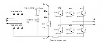
A 12/220 V converter with transistors is another option for making such a device yourself. A variant of the circuit, when using transistors, is shown in the following figure:
This circuit uses IRFZ44 transistors, which, if necessary, can be replaced with IRFZ40/46/48 or IRF3205/IRL3705, and TIP41 (KT819) transistors, which can also be replaced, if necessary, with KT805, KT815, KT817 and the like.
The assembled circuit (device) has the following characteristics: power - up to 0.3 kW, input voltage - 3.5-18 V, output voltage - 220 V, frequency 57 Hz, output pulse shape - rectangular.
The advantages of this scheme are: simplicity and the ability to assemble even for a person with basic knowledge and skills, low cost of components, compact dimensions of the circuit board and the device as a whole, the ability to replace components.
The disadvantages are: the circuit does not provide protection against short circuit currents, the efficiency is lower than that of factory-assembled products, and the transformer is noisy during operation.
Inverter fault detection
The listed simple circuits have the two most common faults - either there is no voltage at the transformer output, or it is too low.
- The first case is either a simultaneous failure of both arms of the converter, which is unlikely, or a failure of the PWM generator. To check, use an LED probe, which can be purchased at any radio parts store. If PWM is working, you will see the presence of a signal at the gates of the transistors by the rapid pulsations of the diode glow (this is especially noticeable in low-frequency circuits). If there is a control signal, check for breaks in the connections of the transformer and the integrity of its winding.
- A large voltage drop is a clear sign of failure of one of the inverter's power arms. You can find a failed transistor in the simplest way - its radiator will remain cold. Replacing the key will restore the inverter's functionality.
Filter elements
After the rectifier there is a filter. Its main purpose is to cut off the entire alternating component of the rectified current. For a clearer picture, you need to draw up a substitution diagram. So the plus goes through the coil. And then an electrolytic capacitor is connected between plus and minus. This is what is interesting about the replacement scheme. If the coil is replaced by reactance, then the capacitor, in the presence of varying current, can be either a conductor or a discontinuity.
As was said, the output of the rectifier is direct current. And when it is applied to an electrolytic capacitor, nothing happens, since the latter is an open circuit. But there is a small variable in the current. And if alternating current flows, then in the equivalent circuit the capacitor becomes a conductor. Consequently, there is a short circuit between plus and minus. These conclusions were made according to Kirchhoff’s laws, which are fundamental in electrical engineering.
Using Amplifiers
Nowadays, specialized stores mainly sell two-channel amplifiers. In addition to the presence of two channels, other characteristics may differ significantly. In this case, it is more advisable to choose those that have high electrical conductivity.
Be sure to keep in mind that the maximum voltage of the amplifiers used should not be less than 220V. Start assembling the device by installing the induction coil. To make the platform on which parts of the system will be installed, a non-conducting material, such as a wooden board, is selected.
Once the coil is secured, install the transformer. The tetrode and amplifier must be close to each other. To stabilize the voltage, you will need 2 filters.
Transformer: we’ll select it or do it ourselves
To assemble the inverter, we only need one circuit element that transforms low voltage into high voltage. You can use transformers from power supplies of personal computers and old UPSs; their windings are designed to transform 12/24–250 V and vice versa; all that remains is to correctly determine the conclusions.
Still, it’s better to wind the transformer with your own hands, since ferrite rings make it possible to do it yourself and with any parameters. Ferrite has excellent electromagnetic conductivity, which means that transformation losses will be minimal even if the wire is wound manually and not tightly. In addition, you can easily calculate the required number of turns and wire thickness using calculators available on the Internet.
Before winding, the core ring needs to be prepared - remove the sharp edges with a file and wrap tightly with an insulator - fiberglass impregnated with epoxy glue. Next comes the winding of the primary winding from thick copper wire of the calculated cross-section. After dialing the required number of turns, they must be evenly distributed over the surface of the ring at equal intervals. The winding terminals are connected according to the diagram and insulated with heat shrink.
The primary winding is covered with two layers of Mylar insulating tape, then a high-voltage secondary winding and another layer of insulation are wound. An important point is that the secondary must be wound in the opposite direction, otherwise the transformer will not work. Finally, a semiconductor thermal fuse must be soldered into the gap to one of the taps, the current and response temperature of which are determined by the parameters of the secondary winding wire (the fuse body must be tightly wound to the transformer). The transformer is wrapped on top with two layers of vinyl insulation without an adhesive base, the end is secured with a tie or cyanoacrylate glue.
What does the control drive consist of?
Frequency circuit diagram.
It consists of three parts:
- a rectifier that provides a direct current potential when connected to the electrical network. The network may or may not be managed;
- a filter element that smoothes the output voltage (capacitance is used);
- an inverter that produces the desired frequency potential, the outermost link near the electric motor.
Self-production of the device
If for some reason it is not possible to purchase a 12V to 220V voltage converter, then it is easy to make an inverter with your own hands at home. First of all, this applies to analog devices, radio components for which can be taken from old equipment. In addition, with self-assembly, you will be able to understand the nuances of construction, which can be useful for repairing devices of this type.
Simple and reliable inverter
There are a large number of different converter circuits. Their operation is based on the use of a master oscillator that controls the operation of transistor switches. And they, in turn, transmit a pulse signal to a transformer, whose task is to convert the signal to a level of 220 volts. The use of powerful field-effect transistors (mosfets) as switches greatly simplifies the circuit design of devices.
IRL2505 mosfets are connected to the outputs of the microcircuit, direct and inverse. The IRL2505's open channel resistance is only 0.008 ohms. This makes it possible not to use radiators at the required power of up to 100 W.
The generation frequency of the microcircuit is set by the R1-C1 chain and is calculated by the formula: f=70000/(R1*C1). The R2-C2 chain is designed to smoothly start the generator. A 78L08 is used as a linear stabilizer for DA2, with a stabilization voltage of +8 volts. Resistors are used with a power of 0.25 watts. Capacitor C1 is of a film type, and C6 is of any type, but designed for a rated voltage of at least 400 volts. The transformer is used with windings designed for 220 and 12 volts.
Transistor circuit
A generator operating at a frequency of 57 Hz is used as the basis for the manufacture of the structure. The master oscillator controls the operation of power switches, made of powerful field-effect transistors. These transistors can be replaced with IRFZ40, IRF3205, IRF3808, and bipolar ones with KT815/817/819/805.
The power of the inverter depends on the number of complementary field pairs at the output and the characteristics of the transformer. The output voltage is 220–260 volts. When using two pairs of transistors, the power reaches 300 watts. Such a converter does not require adjustment and, with proper assembly and serviceable radio components, works immediately. When operating without load, current consumption is up to 300 mA. For reliable operation, transistors are installed on the heat sink through insulating gaskets. Power tracks, in case of wiring on a printed circuit board, are made with a width of at least 5 mm or with a wire with a cross-section of 0.75 mm2.
The essence of the device’s operation is to convert direct voltage into alternating voltage, after which the signal is supplied to a step-up transformer. The primary winding of a step-up transformer from 12 to 220 volts has fewer turns than the secondary. When current flows in the primary winding, under the influence of an alternating magnetic field, an electromotive force (EMF) appears on the secondary winding. When a load is connected to the secondary winding, alternating current begins to flow through it. To calculate the transformer, you can use reference books or online calculators, but it’s easier to take a ready-made one from an unnecessary uninterruptible power supply.
Powerful boost device
Such converters are manufactured using complex circuits and are difficult to replicate even for experienced radio amateurs. For example, a 12 V 220 by 3000 W inverter circuit:
It is almost impossible to carry out such a scheme with your own hands, since it will be necessary not only to correctly calculate the transformers, but also to correctly configure the master oscillator. And such operations are difficult to perform without special equipment.
The generator is made on the TL081 chip. It is powered by a nine-volt stabilizer. The signal in the microcircuit is converted, reduced in frequency and supplied to power switches. The circuit implements output overload protection, and the input is protected by an overvoltage fuse.
Originally posted 2018-04-18 12:30:34.
A second life for uninterruptible power supply!
If you have an “extra” uninterruptible power supply whose battery is completely dead, you can still revive it. To do this you will need to make some small changes:
- Remove the old battery.
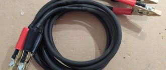
- Solder new wires to connect to the 12 Volt battery.
- At the edges of the wires, install terminals for connecting to the car battery. If the device will be used in a car, it can be powered from the cigarette lighter. But it is undesirable to do this - the high power of the device causes excessive heating of the wires.
To connect household appliances to an uninterruptible power supply, you need to make sockets. The easiest way is to make a carrier from an old surge protector and a piece of wire with a plug, which will include all the equipment.
Voltage converter from 12 to 220 V for a car
Automotive inverters are low-power devices (up to 0.1 kW), with an output signal in the form of a modified sine wave, activated by plugging into the car's cigarette lighter.
Currently, the following models are popular in this group of products:
"ORION PN-70" (Russia).
Device power – 0.9 kW, output signal – modified sine wave, output voltage 220 V, frequency 50 Hz. Provides short circuit protection. The device is equipped with one plug connector (socket) and a USB port.
"AIRLINE API-150-01" (Russia).
The output power of the device is 0.15 kW, the output signal is a modified sine wave. The device is plugged directly into the car's cigarette lighter and is equipped with one plug connector for a voltage of 220 V. The model is equipped with a USB port, its weight is 400.0 grams.
"AIRLINE API-200-02" (Russia).
This model is connected to the cigarette lighter using connecting wires. Device power – 0.2 kW. This model has protection against short circuit currents, one USB port and one socket for a voltage of 220.0 V.
"WESTER MSW250" (Germany).
Power – 0.25 kW, the model is equipped with a short-circuit current protection device, a USB port and a socket for a voltage of 220.0 V. The output signal is a modified sine wave.
"MYSTERY MAC-1000" (China).
Device power – 1.0 kW, number of sockets for 220 V voltage – 2 pcs., USB port.
The weight of the model is 2.6 kg.
Model with phase rectifiers
A simple voltage converter for the home with a phase rectifier must be equipped with a 40 Ohm inductor. This circuit will require chromatic thyristors. Choose your transformer carefully.
Some experts advise using step-down models, but they are not always available for sale. That is why many masters still use power models. This circuit requires only one amplifier. The transformer is connected to the tetrode via a choke.
To increase current conductivity, resonators can be used. Be sure to check the transformer voltage limit using special devices. To prevent the tetrode from burning out, use a zener diode. For this rectifier model, it is better to purchase a two-pin version. At the very end of the operation, do not forget to secure the terminal blocks.
Low Voltage Shutdown
If you use a battery in your design that operates in parallel in a car, then it is recommended to ensure that the converter from 12 to 220 is automatically turned off when the charge is low. It is not difficult to assemble a simple shutdown circuit with your own hands. If the battery is completely discharged, you will not be able to start the engine even from a tow. Therefore, introduce a simple element into the circuit - an electromagnetic relay. These are used in cars, so finding one will not be difficult.
The relay has a lower voltage threshold at which the contacts close. To adjust the torque more accurately, it is necessary to select the resistance of resistor R1. It should be equal to the resistance of the relay winding multiplied by a factor of 0.1. You can implement such a modification without much difficulty in a converter from 12 to 220. Even a novice electrician can connect the relay and resistor with his own hands.
But such a scheme is primitive, and its efficiency is extremely low; it is better to use a modernized one; it maintains more precisely the threshold for disconnecting the battery from the inverter.
Battery and power
The suitability of the converter for a particular purpose also depends on the battery. A boost voltage inverter does not take energy for consumers from the “dark matter” of the Universe, black holes, the holy spirit, or anywhere else just like that. Only from the battery. And from it he will take the power supplied to consumers, divided by the efficiency of the converter itself.
Car enthusiasts know: if you run the starter for 20 minutes, buy a new battery. True, new machines have time limiters for its operation, so perhaps they don’t know. And certainly not everyone knows that the starter of a car, once spun up, takes a current of approx. 75 A (within 0.1-0.2 s at startup - up to 600 A). The simplest calculation - and it turns out that if the inverter does not have automatic equipment that limits the battery discharge, then ours will run out completely in 15 minutes. So choose or design your converter taking into account the capabilities of the existing battery.
The service life of acid batteries does not noticeably decrease if they are discharged with a 2-hour current (12 A for 60 A/h, 24 A for 120 A/h and 42 A for 210 A/h). Taking into account the conversion efficiency, this gives a permissible long-term load power of approx. 120 W, 230 W and 400 W respectively. For 10 min. load (for example, to power a power tool), it can be increased by 2.5 times, but after this the ABC must rest for at least 20 minutes.
Overall, the result is not entirely bad. Of the ordinary household power tools, only the grinder can take 1000-1300 W. The rest, as a rule, cost up to 400 W, and screwdrivers up to 250 W. A refrigerator from a 12 V 60 A/h battery will work through an inverter for 1.5-5 hours; quite enough to take the necessary measures. Therefore, making a 1 kW converter for a 60 A/h battery makes sense.
Design features based on uninterruptible power supply
With a good battery with a capacity of 55 Ah, such a design can maintain normal temperature in an incubator for 100 eggs, for example, for up to a day. Any farmer knows how dangerous hypothermia is for incubators. True, the power of such a device is small; the air conditioner or refrigerator will not be able to work properly.
One drawback of this design is that the standard circuit will not be able to fully charge a car battery. Therefore, when the battery is completely drained, it is necessary to charge it from a normal device that produces a current of more than 5-6 Amperes.
How to make a 12/220 converter with your own hands
A conventional pulse converter has a very simple circuit. Most of the required parts are soldered from the old power supply. True, the output voltage of 220 Volts will be far from sinusoidal and does not correspond to a frequency of 50 Hz. This means that it will not be possible to connect electronics or instruments directly. But there is a solution: installing a rectifier with smoothing capacitors at the output.
The main part of the circuit in the photo is the TL494 PWM controller. The frequency is set by capacitor C2 and resistor R1. Their denominations may differ from those presented.
The other circuit is old, assembled using domestic elements, but produces a voltage of 220 Volts with a frequency of 50 Hz. The generator here is a dual D-trigger, which is an analogue of the foreign CD4013 microcircuit. If necessary, replacement can be made without changes to the circuit. This circuit has many disadvantages: rapid overheating, the mandatory use of a powerful steel core, non-sinusoidal output, noise during operation.
It is possible to do without an adapter if you need to use a drill or other tools. Instead, a gasoline generator is installed - fed from the engine. This device can even charge a dead battery - a handy thing!
Frequency control mode
They are divided into types of engine speed control:
- scalar control (no communication from the reverse side);
- vector control mode (there is or is no connection from the reverse side).
In the first case, the stator with its magnetic field is controlled. Vector control takes into account the action of the rotor and stator magnet fields, improving torque at different rotation speeds. This is the main difference between their control modes.
The vector method is more accurate and efficient. It is more expensive to maintain. It is more suitable for specialists with good professional skills and knowledge. The scalar type control method is the easiest to use. It is used with output parameters that do not require special precision adjustment.