The circuit itself
is a simple sound frequency generator (one might say a buzzer) and is assembled using only four parts:
How the tweeter circuit works
R1 sets the offset to the base of VT1. And with the help of C1 feedback is provided. The speaker is the load of VT2. The sound frequency can be adjusted by selecting capacitor C1
Necessary radio parts for tweeter assembly
1. Two transistors. It is best to use a complementary pair (let me remind you that transistors with the same parameters but different conductivities are called complementary). Almost any will do: from the old Soviet ones: KT315 and KT361, for example, from imported and inexpensive 2SA1015 and 2SC1815.
2. Speaker. You can use absolutely anything: from a Chinese player, from an old tape recorder, or just an earphone.
3. Capacitor: Absolutely any with a capacity ranging from 10 to 100 nanoFarads. If suddenly someone has forgotten how to determine the capacitance of a capacitor by its digital code, then you can look at the reference materials section: there is a separate section Digital code of capacitors
4. Voltage source. You can use any battery: even a 1.5V “finger” battery, even a 9-volt “crown”, there is no difference - only the power will change.
5. Resistor. Again, any type (you can even adjust it) with a resistance from 10 to 200 kOhm.
6. Switch. You can use any toggle switch, button.
A correctly assembled circuit does not need configuration and starts working immediately. If suddenly it doesn’t work, but what: come to our FORUM, we’ll figure out why (and even if it works, come anyway!!)
A watchdog device using a single transistor is the simplest circuit that even a preschooler can assemble.
Your property is often invaded without permission, while you are doing important work?)
It's time to forget these problems! I present to your attention a circuit of a watchdog device with just ONE! Thanks to this scheme, you will be able to secure your home and take all necessary measures to eliminate problems that arise in a timely manner!
Scheme and principle of operation
And here is the diagram
The pinout (pin location) of the KT815B transistor looks like this:
The principle of operation is very simple. When the security wire breaks, the buzzer starts beeping. A thin security wire can be strung across the doorway.
To describe the operation of the circuit more precisely, it would look like this:
Let's draw a diagram according to GOST for ease of perception
As long as our security wire is intact, current will flow in the circuit plus the batteries—a 100 K resistor—and the security wire. All current will flow through the security wire, since its resistance is very low. Since all the current will flow through the wire, it will not be enough to turn on the transistor. The transistor opens only when its voltage between the base and emitter is 0.5-0.7 Volts.
But... as soon as the security wire breaks, the voltage at the base immediately increases sharply, that is, it becomes more than 0.5-0.7 Volts and current begins to flow through the base-emitter. Since current flows through the base-emitter, therefore, the transistor opens. And once it opens, it means that current begins to flow through the circuit plus the batteries—buzzer—collector—emitter. While the current is flowing through the buzzer, it screams like it was scalded.
Assembly and operation in practice
The circuit consists of a KT815 transistor with any letter. I took this one:
What are those strange markings on the transistor? Previously, this is how Soviet transistors were designated. Experienced radio amateurs will immediately determine that this is a KT815B transistor. For beginners, I advise you to download the program Transistor v1.0, which will allow you to easily identify Soviet transistors, even with color coding.
Here's an example of a transistor I'm using in a circuit:
The circuit also has a buzzer:
A buzzer is a sound emitter. When applying a constant
tension, it begins to squeak with a high-frequency unpleasant monotonous sound.
I bought it on Aliexpress for 0.7 bucks using this
link.
Buzzers are often confused with piezo emitters (pictured below):
If we disassemble the buzzer, we will see on the board a simple circuit of a frequency generator made in SMD design, as well as the piezo emitter itself, soldered with copper wires to this board.
So if you buy a buzzer from a radio store, make sure that the seller does not slip you an ordinary piezo emitter.
Instead of a buzzer, you can take a low-power light bulb or some kind of actuator that will be turned on via a relay. In this case, do not forget to protect the transistor by connecting a protective diode in parallel with the relay coil:
Well, here’s a video of the entire circuit in action. The orange wire is a type of security wire.
I think many people are familiar with the situation: I forgot to turn off the headlights and drained the battery. Yes, you might say, many cars have a beeper installed from the factory, reminding you that the lights are not turned off. My car did not have such a device. I have read many times how people installed buzzers from Scorpio and other cars.
I have been using a very simple device on my car for several years now; it has 2 functions:
1)—
When the door is opened, it signals that the lights are on.
2)
—Indicates that the cooling system fan is turned on.
I used a 12 volt buzzer as a signaling device. In order for the sound to be intermittent, I assembled a simple generator on the K561LA7 (its power supply is 12 volts).
The C and R denominations are selected according to taste. I took the door open signal from the driver's door switch. The only thing I didn’t do was install a diode at the input and that’s why the buzzer beeps when I open the passenger door. Alarm about the operation of the cooling system fan, only to attract attention so as not to overheat the engine.
I also installed LEDs parallel to the relay windings (and embedded them in the panel near the driver’s left foot) in order to know what mode the buzzer is signaling. This is optional.
A simple musical instrument can be made in less than half an hour. Of course, its sound range, frequency, and, as a result, tone are very different from real professional instruments, but due to its simplicity, it will be an excellent device for assembly by a novice electronics engineer.
The basis of the circuit is the well-known and mega-popular 555 microcircuit; its period, and hence the frequency, can be controlled using the values of some resistor values and capacitance. As you can see, we have many resistors with different values, so by pressing a certain key you turn on a resistor of a certain resistance in the circuit and a sound is heard in the sound-emitting device. By pressing another key, with a different resistor, you will create sound vibrations with a different tone. When two or more buttons are pressed, resistors are connected in parallel, a different resistance is created and the sound changes. By combining these presses in a certain sequence, you can create primitive melodies - it's funny. For flexible settings, I recommend connecting a variable resistor, rotating its shaft to achieve the desired sound tone, then measure its resistance with an ohmmeter, without twisting anything, and replace it with the nearest fixed resistor available. If you find a capacitor, you can turn it on as a trimmer, but some may have problems measuring its capacitance - not all multimeters are capable. Particular attention is paid to the keys. Standard tact buttons are too rigid and require relatively significant force to close their internal contacts. I recommend using them only with a certain lever, similar to a piano key. I found buttons that require extremely little effort to press and also have a long cylinder for pressing. By briefly listening to the output signal while changing the angle of rotation of the rotor of the variable resistor, in my opinion, good sound frequencies were selected for each key. Below is a table of frequency and resistance of a resistor suitable for this purpose. If you wish, you can easily calculate the ratings of radio components for the frequency you are interested in, in those. The documentation indicates the maximum operating frequency of the timer is 200 kHz. The human ear hears vibrations with a frequency of 20 Hz - 20 kilohertz, so the capabilities of this electronic component are even more than we need. I'll briefly show you how it's calculated. The first resistor was selected at 4.7 kOhm - 4700 Ohm. From the basic formula taken from the technical documentation 555 it is easy to derive the resistance R2 for given R1, C1 and the actual selected frequency. The entire board, thanks to surface-mount components, is extremely small. Any NPN transistor, you can use BC847, the location of its BEC is standard, the same as for all bipolar transistors in the SOT-23 package. The power supply is 5-18 V, but it works even from one lithium-ion cell. It is also possible to insert such a circuit into an old non-working children's melodies synthesizer. It is better to turn the fifth pin of the “Control” microcircuit to negative through an output capacitor with a capacity of about 100 nF.
When a low-impedance speaker is connected, the transistor heats up noticeably; this can and should be prevented by increasing the value of its base resistor or by turning on a high-impedance speaker from an old phone. In my copy, it turned out that the buttons with resistors were placed on one board, and the microcircuit on the second: I connected them with tinned tin plates. It is better to fasten the buttons not only with contacts using solder contacts, but also to fill this matter with hot glue or epoxy, when the values for the desired sound have already been precisely selected.
Sometimes drivers, especially beginners, forget to turn off the turn signal after completing a maneuver. The standard clicks are sometimes not audible if the music is playing loudly. An audible 12 v turn signal, made by yourself, will help correct the situation. Instructions for making your own tweeter are included in this article.
[Hide]
Sound doubler for direction indicator - diagram
Nowadays, modern cars are equipped with direction indicators that automatically return to their original position when the maneuver is completed.
But this does not apply to all models, and there is no need to talk about budget and old cars. We have all seen moving vehicles on the roads with their turn signals on, when the driver simply forgot to turn them off.
This especially affects novice car enthusiasts. This will greatly disorient other road users and may lead to an emergency.
The sound of the turn signal - a sound backup - will help you avoid such an unpleasant situation. The circuit and design of such a device will be discussed in today’s article.
The device circuit is very simple. The idea is to connect a miniature board to the car's dashboard indicator lamps (+U1 and +U2). Essentially, when the turn signals are turned on, power supply is simply applied to the circuit.
The circuit itself is two generators connected in series. Each time the indicator is turned on, the circuit plays several intermittent sound signals. The number of beeps each time the pointer is turned on, as well as their tone, can be configured.
So, we have two generators DD1.1, DD1.2 - the number of sound signals when the indicator is lit and DD1.3, DD1.4 - the tone of the reproduced sound vibrations. The first generator controls the start of the second, i.e. the generator on DD1.3, DD1.4 works only when the first one works.
The frequency with which the generators operate is determined by the parameters of their RC circuits: R1C1 and R2C2. This is what setting up the circuit is all about. By selecting capacitor C1 you can regulate the number of sound vibrations, and by selecting C2 you can regulate their fundamental tone.
Almost any buzzer (piezo emitter) designed for a voltage of 12 V without a built-in generator can be used. For example, such as HCM1212A or HCM1612A.
Printed circuit board (link) - single-sided for installing SMD components. DD1 chip in SO-14 package, resistors and capacitors in 1206 packages. You can use any diodes of suitable size, for example, DL4148.
Contact pads: +U1 and +U2 - connection to the pointer indicator lights, GND - ground, BZ1 - connection to the piezo emitter.
I know that many people do not like surface mounting or are simply “unfriendly” with it. This is also not a problem. In general, everything can be done by hanging installation, the main thing is that there is somewhere to place it all later. The DD1 microcircuit is replaceable with our K561LA7 with the same pinout, the resistors are ordinary MLT, and the capacitors are K10-17.
Source of the article: https://xn--100—j4dau4ec0ao.xn--p1ai/zvukovoj-dublyor-ukazatelya-povorotov-sxema/
DIY turn signal, diagram – Crafts for cars
Drivers often forget to turn off their turn signals. Therefore, I propose to assemble and place an additional signal there that will be heard and inform you that the turn signal is working. The device circuit is based on a generator built on the K561LE5 microcircuit.
Characteristics of K561LE5:
Supply voltage - from 3 to 15 V. Current consumption - no more than 5 microns. Low level output voltage – 3 V. High level output voltage – 7.5 V. Low level output current – 0.6 mA. High level output current is 0.3 mA. Temperature range – from -45 to +85 ° C.
3P-3 was used as a piezo sound emitter, but analogues are also suitable. Using a variable resistor, we adjust the volume and tone of the signal; in my case, the volume resonance was set to maximum.
The circuit has protection against reverse polarity; for these purposes, a diode is installed at the positive power input. Almost all corrected diodes will do (1N4002, 1N4003, ,,, 1N4007).
Audio signal generator circuit
List of radio components
Resistor with a nominal value of 10 kOhm (5 kOhm-50 kOhm will also do). Trimmer resistor with a nominal value of 100 kOhm (68 kOhm-500 kOhm will also work). Capacitor 100 µF (suitable from 47 µF to 500 µF with a voltage of at least 16 volts). Capacitor 0.1 µF (suitable from 0.1 µF to 0.47 µF). Any diode. Piezo emitter -3p-3. Chip K561LE5. LE5 can be replaced with LA7.
The board size is approximately 20x22mm. We place the board with the piezo emitter into the housing. We connect the power wires parallel to the wires coming from the relay connector (turn signal breaker).
And so, carefully pull the terminals out of the connector, wind the wires, insulate them and put the terminals back in their place. Also, turn on the turn signal and use the trimmer to adjust the volume and tone of the sound. The signal can also be clearly heard against the background of loud music in the car.
Board in .lay format download...
That's all, good luck!
Making a car craft - making an audible turn signal for your “Swallow”
Sometimes drivers, especially beginners, forget to turn off the turn signal after completing a maneuver. The standard clicks are sometimes not audible if the music is playing loudly. An audible 12 v turn signal, made by yourself, will help correct the situation. Instructions for making your own tweeter are included in this article.
Instructions for making a beeper for turn signals
You can make an audible turn signal for your car with your own hands within 15 minutes, without contacting a car service about it. To create such a duplicate turn signal, you will need a K561LN2 microcircuit; it will serve as the basis. In addition, you need a buzzer, but without a built-in generator.
Universal audio repeater
You can take a buzzer that has a built-in generator if you like its sound. In this case, we look at an example of connecting a buzzer to a standard low-frequency generator. Having connected to the bass generator, you should turn the tuning knob and select the most suitable sound. Now you can reproduce it using the K561LN2 microcircuit and a generator as a basis.
Tweeter connection diagram
The device diagram can be represented in two parts:
- The generator is assembled from two logic elements INV1 and INV2, to which a timing RC circuit is connected.
- The amplifier consists of three logic elements INV3, INV4, INV5 paralleled with each other. They are connected in parallel to amplify the switched current. Thanks to the amplifier, the generator can operate with a load in the form of a boomer.
The tone of the audio repeater is adjusted by changing the value of C1 and R1. When connecting the device, the negative pole is attached to the vehicle ground, and the positive pole is taken from the emergency stop button through “decoupling” diodes.
To determine the button terminals, you should use a multimeter. On it you need to select the mode for measuring DC voltage. After turning on the left turn signal, you need to look at which terminal the +12 Volt voltage periodically appears. Similar actions must be performed by turning on the right turn signal.
Assembled audio device
In this case, the device is mounted mounted. For the housing of the sound turn signal, a 2 mm syringe with a piston removed from it is used. The wire comes out of a narrow hole - the nose of the syringe, and the buzzer is attached to the back of the syringe using hot-melt adhesive.
Thus, it is easy to assemble an audio turn signal repeater with your own hands using a microcircuit and 5 logic elements. At the same time, you can save time and money on visiting a car service center.
DIY sound piezo emitter | DIY master class
The circuit presented in this article is very easy to repeat and should not cause any difficulties in assembly. It can be used in various devices for sound notification. For example, an alarm system, sound duplication of a turn signal in a car or bicycle, a low battery signal, and so on. You can, of course, take a ready-made beeper, for example, from an old Chinese alarm clock, musical card or other devices, but I decided to make it myself with my own hands. It's more interesting that way. Another goal of the assembly is to popularize youth’s passion for radio electronics. If this site can captivate at least a few people with such an interesting and good cause, then its task can be considered completed. I took a simple, but proven scheme. I don’t even remember where I got it from.
Piezo sound emitter circuit
Parts for assembling the horn circuit
Parts for the circuit can be used in a very wide range. For example, La7 microcircuits from the K176, K164, K564, K561 or K561LE5 series or imported analogues. In order not to solder and desolder the microcircuit, it is best to take a special contact pad and solder it into the circuit (it costs pennies), and replacing the microcircuit will take seconds, and during soldering there is no risk that the microcircuit will overheat or be damaged by static electricity. In addition, you can easily test different brands of microcircuits for performance. Capacitor C1 is polar with a voltage of at least 15 volts and a capacity of 47 to 500 microfarads. If you want the buzzer to immediately stop after turning off the power, then this capacitor must be excluded, otherwise after turning off the power, the sound continues until the capacitor is discharged. Ceramic capacitor C2 from 0.1 to 0.47 microfarads. They are indicated by numbers on the cover - 104, 154, 224, 474. Resistor R1 from 5 to 50 kilo Ohms. Any power, but less is better. So that the dimensions are not large. Potentiometer R2 from 68 to 500 kilo Ohms. The power is the same, less. You can use any diode you like. It is used to protect the chip from improper power connections. You can do without it altogether.
Sound emitter ZP-3 or any similar.
How to connect ZP-3? If the ZP-3 sound emitter is new, then you need to solder wires to it, as in the photo. Soldering is easy if you use flux. We solder one wire to the membrane. Solder the second wire to either of the two terminals. The supply voltage of the circuit is 12 volts. This could be a battery, rectifier or any other DC source. The sound tone of the device depends on the values of the circuit elements, so you can experiment by changing capacitors and resistors to achieve a sound that you like. In order not to make a printed circuit board, it is best to take and use a breadboard; it turns out much easier and faster.
With proper assembly and serviceable parts, the circuit starts working immediately and does not require adjustment. If you don’t like the tone, then adjust the potentiometer to your taste. The signaling device is assembled.
Watch the tests of the assembled buzzer in the video
sdelaysam-svoimirukami.ru
Do It Yourself (Ogonyok) 1998-04, page 53
SOUND
REPEATER-
ALARM
In the almanac “Do It Yourself” No. 2 for 1996, an article by S. Antoshkin “My Ar porridge” was published, dedicated to a homemade sound repeater for the light signal of the direction indicators in a car.
An audio repeater is a very useful and necessary thing, and I decided to make this simple device according to the diagram given in the article.
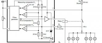
The assembled device did not work at first. Then I found the reason. An error crept into the illustration, which did not allow the assembled device to work. By the way, some other errors were also discovered. In particular, the phone's resistance cannot realistically range from 30 to 3000 ohms. In order for the sound to be heard, the resistance of the dynamic head must be about 50 ohms. With a higher head resistance, the sound simply will not be heard, and with a lower resistance, the transistor current will exceed its permissible maximum current.
The signaling device, the modified diagram of which is shown in Fig. 1, is an asymmetrical multivibrator (the convenience of this circuit is determined by the use of transistors of different structures, which allows you to do without many parts).
Oscillations in the circuit arise due to positive feedback between the transi collector
following the published
side VT2 and the base of transistor VT1 through capacitor C1.
The following elements are used in the circuit: transistor VT1 type MP42, transistor VT2 type MP38, resistor R1 type MJ1T 0.25 with a nominal value of 4.7 kOhm, capacitor C1 type MBM with a nominal value of 4700 pF, telephone BF1 brand N63K (from a telephone set) with a resistance of 56 Ohms .
Assembled according to the diagram shown in Fig. 1, the sound repeater works fine, but it has some drawback - the repeater starts beeping immediately after turning on the turn signal. And this is not very convenient, since in practice there are often cases
Source of the article: https://zhurnalko.net/=sam/sdelaj-sam_ogonek/1998-04—num53
Homemade product that duplicates the operation of car turn signals
Many drivers forget to turn off the turn signal after passing through an intersection, misleading other drivers. To prevent this from happening, I put together a homemade product that duplicates the operation of the turn signals with an audible signal. Here is a homemade diagram
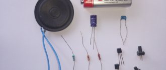
The circuit is very simple, consisting of a sound generator consisting of two transistors, two capacitors, one resistor and a TK-67 or TA-56m telephone capsule at 50 ohms. To do this we will need the following materials and tools:
1-Transistors MP-25, MP-37, resistor MLT-0.25W with a resistance of 1 kohm, electrolytic capacitor with a capacity of 5 microfarads 25V, capacitor MBM with a capacity of 0.05 microfarads, telephone capsule TA-56m 50ohm, switch. 2-soldering iron, solder, rosin, tweezers, wire cutters, circuit board with petals from any old TV, installation wires. We assemble as follows:
Step 1 - Check the radio components with a multimeter
To do this, set the device to measure resistances of 2000 ohms, connect the black probe of the device to the base of the MP-25 transistor, and the red one to the collector, the device should have a resistance of about 170 ohms.
Next, we connect the black probe to the base, and the red one to the emitter, on the device too - 170 ohms.
Now we swap the probes, there should be - 1 on the device.
We measure the resistance between the emitter and the collector - on device -1.
We check the MP-37 transistor in the same way, in this case the red probe goes to the base, the black probe goes to the collector, and then to the emitter, the device should read about 170 ohms. We swap the probes - it shows -1. K-E resistance – 1.
We check the resistance of the resistor, as shown in the photo.
We also check the capacitors and telephone capsule.
Step 2 - solder the parts onto the circuit board, first solder the jumpers between the petals from the wires. Then we solder the capacitors and resistor, and after that we solder the transistors and then the switch and capsule.
Step 3
We check the functionality of the homemade product by connecting + 12V power to it from the power supply or car battery. The generated signal must be audible in the telephone capsule. Step 4 - place the homemade product in any suitable case, at your discretion. This is not shown in the photo. Next, install the homemade product in the car. With a minimum of parts, there is great benefit for the driver. Delivery of new homemade products to the post office
Receive a selection of new homemade products by email. No spam, only useful ideas!
*By filling out the form you agree to the processing of personal data
Become the author of the site, publish your own articles, descriptions of homemade products and pay for the text. Read more here. usamodelkina.ru
Sound turn signal
In order not to forget to turn off the turn or handbrake lever, I suggest adding a simple device to your car - a signaling device. The sound alarm is assembled on a common and inexpensive K155LA3 microcircuit. The signaling device is connected to the turn signal or handbrake warning lamp.
The circuit diagram of the alarm is shown below.
A high-tone generator is assembled on DD1.1-DD1.2, controlled by a low-tone generator assembled on DD1.3-DD1.4. The frequencies of the generators are selected by capacitors of 0.47 μF and 47 μF, respectively.
A capacitor connected in parallel with the zener diode serves to dampen the generator and can be excluded from the circuit.
The circuit is assembled on a small PCB board. The housing can be two screens from inductors from old tube TVs.
The alarm can be installed in the instrument panel, where it is connected to the warning lamp.
A. Zotov, Volgograd region.
SHARE WITH YOUR FRIENDS
Acoustic turn signal repeater for scooter - radiohlam.ru
Another useful thing from Rus_lan. This time we will need an electromagnetic emitter from the motherboard (AC-1205G or similar), a 555 timer and a number of diodes, conductors and resistors, and we will make an original audio turn signal repeater for a scooter.
Scheme:
Details:
- D1, D2 - SS12 diodes (any diodes 0.5-1 Ampere, ≥18-20V will do)
- D3 - any low-power diode with reverse voltage ≥18-20V
- C1 - electrolyte 100uF x 16V (even better at 25V)
- C2 - ceramics 0.1 µF, C3 - ceramics 10 nF
- T1 - any field-effect transistor for a current ≥0.5 Ampere (you can use a bipolar instead of a field-effect transistor; how to calculate a switch on a bipolar transistor is described here
- R1=470 Ohm, R2=7.5 kOhm, R3=10 kOhm, R 4=160 kOhm
- What kind of beeper and what kind of mikruha is needed - I have already written.
- To control the volume, you can add a variable resistor R5 (shown in dotted lines).
In fact, the device is an audio frequency pulse generator on a 555 timer, the output of which, through a transistor power amplifier, is connected to an electromagnetic emitter.
How to adjust the frequency and duty cycle of the generated pulses is described here. With the indicated ratings, a frequency of about 800 Hz and a duty cycle of about 1.06 are obtained.
Board layout:
Finished device:
The “turn signal 1 +” and “turn signal 2 +” terminals are connected to the turn signal indicator lamps on the instrument panel.
Quote from the forum (from the author of the device): “The sound turned out to be clear and loud, you can hear it well”
.
radiohlam.ru
Top 10 articles
- A simple and reliable DIY metal detector - 208,856 views.
- DIY microwave oven repair - 194,941 views.
- Charger from a computer power supply. — 191,247 views.
- Simple DIY metal detector - 187,152 views.
- Car chargers. Scheme. Principle of operation. — 166,723 views.
- A simple and reliable thermostat circuit for an incubator - 157,938 views.
- A variety of simple circuits on the NE555 - 125,104 views.
- Simple automatic charger - 123,237 views.
- DIY moonshine still - 111,303 views.
- Simple pulse metal detector "PIRAT" - 106,764 views.
Communities › Electronic Crafts › Blog › Help me choose the sound of the turn relay
I appeal to the collective mind! I made a version of a regular three-pin turn signal relay to work with LEDs. With adjustable threshold and indication of burnt out lamps. On a smart key. Don't ask why I'm reinventing the wheel, etc. etc. To sound, you need to select the most suitable buzzer sound. Please watch the video with sound, not for personal gain. The very first buzzer is the best, KMK, but it is impossible to buy it in small quantities. That leaves three options available. I bought a dozen different ones to try, and more or less only three of them fit. We need the opinion of a large number of people on which buzzer to choose
Translator
We are in social networks:
Subscribe RSS
Subscribe to our RSS feed to receive site news. Stay connected!
Briefly about the site:
Master Vintik. Everything with your own hands!
— this is a site for those who like to make, repair, and create with their own hands! Here you will find free reference books and programs. The site contains simple diagrams, as well as tips for DIY beginners. Some of the repair schemes and methods were developed by the authors and friends of the site. The rest of the material is taken from open sources and is used for informational purposes only.
Do you like to tinker and make crafts? Send photos and descriptions to our website by email
or through the form.
Programs, diagrams and literature - all FREE!
If you like the site, add it to your favorites (press Ctrl + D)
, and you can also subscribe to RSS news and always receive new articles on the feed. If you have a question about a pattern or craft? Welcome to our forum! We are always happy to provide assistance in setting up circuits, making repairs, and making crafts!
Source of the article: https://www.mastervintik.ru/zvukovoj-signalizator-povorotov/