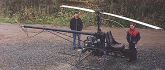
Good day to all! In the comments to this review, I promised to review my 3D printer with CoreXY kinematics using steppers from a matrix printer. If anyone is interested, please go to cat. First, a little background on the appearance of this craft: About three years ago I received four sets of stepper motors from an Epson FX890 printer for free. It uses two stepper motors, we are interested in the EM-336 (aka STP42D-221-03) from Shinano Kenshi. These engines would have been lying around until the second coming if a review from a fellow countryman had not appeared here smirnov
(for which I thank him very much). So, after reading my hands itched, and as a result of this itch, two years ago, a product was born in the form of Pryusha i3 on an acrylic frame, with Bowden feed and an ATX power supply. In order not to scare readers, I will post the photo under a spoiler. Prusa i3
I apologize for the mess on the table, the printer was assembled and is in operation.
After assembling and setting up the pryushya, two steppers remained, then another pair was added to them and my hands itched even more. One day, while reading a magazine, I came across the SmartCore project and everything fell into place - there was a printer for printing parts, experience in assembly, steppers and some spare parts were available, and the Chinese brothers were there to help.
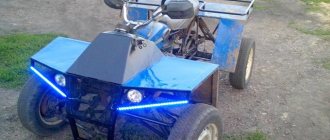
The result is a printer like this:
Dimensions (H*W*D) - 38*32*27 cm (without coil mounting) Mechanics:
Kinematics - CoreXY Dimensions of the printing area (X*Y*Z) - 124*130*105 mm Dimensions of the guide axes X, Y - diameter 6 mm, length 200 mm GT2-20 spools are used, GT2 belt width 6 mm Z axis - diameter 8 mm, length 220 mm, moved by an M8 screw pin.
Extruder - Bowden MK8 Hotend - Chinese E3D V6, 1.75 filament. Electronics:
Power supply 12V 10 A (Chinese) Arduino Mega 2560, RAMPS 1.4, MKS Mini 12864LCD Drivers - 2*TMC2208 (X,Y axis), 2*A4988 (Z axis, extruder) Mechanical limit switches.
Software:
firmware - Marlin 1.1.5 slicer - Simplify3D 4.0.1
Additional photos
Bearings
What does it affect? Noise level, print quality, evenness of layers and edges of the part.
Options. And again it all comes down to budget. You can order a bearing in a block (model SC8UU, for example, here). You can just use a linear bearing LM8UU. You can choose bronze or brass bushings for your car generator. The main thing is to choose the right size.
Finally, you can order bearings from the 3D printer from whom you will buy parts for your printer (more on this below). Ready-made bearings of all sizes are available here.
Remember, for Prusa i3 you need 12 linear bearings .
Financial advice . Don't rush to order bearings in China. It's not a fact that it will be cheaper. Options for 40 - 60 rubles apiece can also be found in the “native lands”.
Issue price: 600 rubles.
Now actually how it was put together, what difficulties there were and how they were overcome.
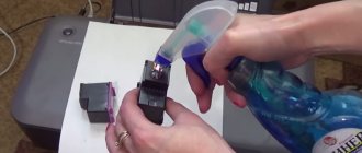
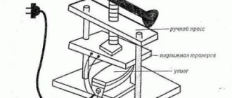
To begin with, you need to convert the EM-336 stepper motor from unipolar to bipolar, remove the installed spool (my brother pressed it out for me on a press, but you can also try it with a grinder).
Rework
The conversion from unipolar to bipolar is described in detail and beautifully in the article Converting a stepper motor from unipolar to bipolar on 3d today, it’s a pity the article came out a year after my torment, it’s good there are good people, user wolfs_SG
from the TriDashnik forum thank you very much! I got it like this: it was
became
Housing
To calculate the housing and parts for the necessary components (thickness and length of the shafts, dimensions of the print area, the method of moving the Z axis - on a screw stud or on a belt), go to the Smartcore project page on YouMagine, it describes what components are required and in the Documents section scripts for OpenJSCAD. I used v.1.2 to calculate the body and parts (except for the Z axis, because in this version of the script there is no option for calculating the axis on the stud) and v.1.0.2 to calculate the parts of the Z axis. (Currently on YouMagine that something is broken and the scripts do not open. To open, you can save the scripts to disk, go to openjscad.org and load the script saved on disk). After calculation, the parts are saved in stl in one file, and I had to resave the required parts into different files.
I already calculated the dimensions of the case myself (for the side walls, where the Y-axis fastenings are located, it is better to add a couple of centimeters to the calculated ones), to suit my layout, then I ordered sawing and gluing the edges from 10 mm thick MDF at the market from kitchen dealers. I was very surprised when I picked up the order - the cost turned out to be $5, taking into account the fact that the acrylic frame with fasteners and studs cost me $40. Then he cut the necessary holes and windows himself and assembled them with self-tapping screws. For beauty, I printed white caps and glued them onto the heads of the screws with hot glue. I’ll tell you below where the bunch of round holes came from.
XY axes
After assembling the body, it was time to print the parts. Without rework, I initially printed 7 parts - the carriage, the X-axis guide mounts, the Y-axis distant guide mounts, and the stepper mounts (aka the front Y-axis guide mounts). All parts were printed using filament-free transition PLA with 50 or 60% infill. When assembling the Y axis, a jamb came out - when trying to fix the guide in the right front mount, the seat under it cracked. But with the left part it turned out even worse - when printing, I did not take into account one important fact - in printer steppers only 23 mm of the axle sticks out of the body, and due to the design, the left spool is higher than the right, and it turned out that with the original part the length of the stepper axle was not enough. I immediately started considering options with different crutches, but then it dawned on me - I have a printer, a bunch of plastic and Thinkercad! Both mounts were imported into Thinkercad, the seat for the guide was strengthened in them, and the motor in the left mount was raised 12 mm up. Now after printing and installation everything was in accordance with the intended design.
I still don’t quite understand how the limit switches are attached in the original, and the mounts for them were designed in Thinkercad.
Photos of limit switches
X axis limit switch
Y axis limit switch
Z axis limit switch
Lyrical digression:
In general, Thinkercad is our everything! I tried to design in the compass - it didn’t work, I didn’t get further than registering and installing the client in Fusion 360, OpenSCAD is a good thing if you need to change parameters, but it’s not the same - all this had to be studied. “He has become old, lazy” ©White Sun of the Desert. I wanted something like Windows Paint, only in 3D. And then Thinkercad came to hand! If you understand the primitives, addition and subtraction, you can design simple parts or correct imported ones. The only thing that is really missing is a tool for chamfering - manually is often tedious and lazy. In general, I recommend it to anyone who doesn’t have time or is too lazy (like me).
Let's continue.
Hotend
I didn’t like the hotend mount and its cooling from the original project and I used the mount from this project, but with some changes (I cut off the induction sensor mount and trimmed it a little around the edges to fit into the carriage).
hotend mount
print as in the picture, the left part with supports.
If the left part is turned 90 degrees along the X, the layers where the nuts were inserted are torn apart, despite 100% filling. And so - 3 perimeters and off we go. Cooling the hotend
I used the cooling from this project, I just took the cooling for the left hotend and turned it 90 degrees on mine. As I indicated at the beginning, the hotend is a Chinese E3D V6, 1.75 filament, currently 0.4 nozzle. Thermal barrier passes through a 4 mm Teflon tube all the way to the nozzle. At one time I had a lot of trouble with pryusha, and now these are the only ones I use. To cool the hotend, a 3010 fan is used, it’s enough, they’re just noisy (we need something better, we’ll just have to negotiate with a toad). To cool the part there is a 5015 turbine, but it only blows on one side of the part. There are plans to install radial airflow.
Carriage with hotend
Z axis, table
The fastening of the Z-axis guides and the table fastening are taken from this project, but again with changes, besides, in this project and in the original, the seat for the bearing is shifted in the upper fastening. Also, after assembly, it turned out that the linear bearings were hanging in their seats, which was fixed using FUM tape. The table was made from a piece of stainless steel 15*15 cm, 1.5 mm thick. Calibrating the table is done the old fashioned way, by tightening the screws on the corners of the table and a piece of paper. There is no heating, I print with PLA plastic. The table is covered with ordinary 4 mm window glass, secured with office clips. On the glass is a sticker, trimmed to the required size. I bought it on Ali at the Big Tree Tech store and the impressions are very contradictory - everything was immediately glued normally and removed without effort, but as I used it, it became more and more difficult to remove the printed material (if you look closely you can see two deep scratches from a spatula), and the first layer goes on normally only if you wipe it alcohol.
Z axis and table
The history of the origin of holes in the walls
After assembly and setup, I turned on the printer and was scared - when moving along the XY axes, there was a sound as if two pioneers were standing next to each other with drums and beating drums on them. To reduce this effect, I took crowns and drilled holes, but the effect of such an upgrade was minimal. And the project was abandoned. After some time, I read an article on YouTube about replacing and using TMC2208 drivers. The drivers were ordered and installed after a month of waiting. After installation, the effect is amazing - the loudest unit is the same fan 3010. And the cut holes had to be refined, but there is something to hold onto when carrying it

Electronics and firmware
The standard kit for a beginning designer is Arduino Mega 2560 + RAMPS 1.4. Arduino with its quirk - it works fine with the computer on the included half-meter USB cable. On the longer ones it’s all pitchforks. Changing ports, USB 3.0 - purple, doesn't work and that's it. For graphic display and working with a memory card, I initially wanted to do it on OLED, as in this article. I bought everything, assembled it, configured it, turned it on... and it didn’t take off. The image appears for a second and disappears. I couldn’t understand why this was so, and my knowledge of Arduino construction is not enough. To remedy the situation, I ordered an MKS Mini 12864LCD on Banggood for $9 (at that time coupons of 5 from 10 for points still worked, there was time). When purchasing, keep in mind that RAMPS requires an adapter. With this controller everything went more fun - everything took off the first time. The controller had to be placed somehow beautifully - and again I took the model from this project and creatively redesigned it. The drivers are written above - 2 * TMC2208 (X, Y axis), 2 * A4988 (Z axis, extruder).
The drivers were set to a current of 0.7-0.8A. When setting up the TMC2208, there is a serious nuance - the current is adjusted with the motors turned off!
When I changed the A4988 to the TMC2208, I didn’t touch anything in the firmware, I didn’t remove the jumpers in the RAMPS either, I just turned over the stepper connectors (you could not touch anything, then in the firmware it was necessary to change the INVERT_X_DIR, INVERT_Y_DIR parameter, but due to natural laziness, unroll connectors turned out to be faster).
And I almost forgot, it is highly recommended to go to the printer menu and reset the EEPROM settings
. Since I print PLA and there is no table heating, it is powered by a 10A power supply, which is quite enough. To make the sandwich of mega, ramps and drivers less heated, an 8 cm fan from an old power supply is used (according to my suspicions, it is also from an AT power supply unit and is about 30 years old, but quite quiet for its age).
To manage everything, Marlin 1.1.5 is used (at the time of assembly this was the current version). The firmware was taken from marlinfw.org and configured from scratch. Since the quilt and belts were already assembled, the same spools and pins were used, almost all the main parameters were taken from the quill firmware. Since CoreXY kinematics are used, I almost broke my head with these parameters:
#define INVERT_X_DIR true #define INVERT_Y_DIR true #define INVERT_Z_DIR true I took them from the firmware of the original project, looked at others, turned over the connectors of the steppers and even though you didn’t crack the carriage moved along the XY axes as it should - if one axis is normal, then the second one is fine inversions. But in the end I found the required combination and everything worked as it should. If anyone is interested, here is a link to Google Drive with the firmware.
Electronics and firmware
The spool holder remains. This is the essence of two projects - a mount and a reel holder. Since I print on the balcony, and the printer itself is stored in the room, it turned out to be very practical and greatly reduces the storage space.
Reel holder
Preparation for use
If everything is connected correctly, you can proceed to the next operating instructions.
Instructions →
Useful materials on some parameters of our firmware
- My configured and working version of the firmware for this printer and extruder. It is slightly calibrated to fit the parts we ordered.
We upload the firmware via the Arduino IDE 1.0.6, select Auto Home on the printer screen, and make sure that the limit switches are connected correctly and the steppers have the correct polarity. If it moves in the opposite direction, simply turn the terminal on the motor 180 degrees. If after starting to move you hear a nasty squeak, this is the squeak of the stepper drivers. It is necessary to tighten the trimming resistor on them according to the instructions.
I advise you to start printing from PLA plastic: it is not capricious and sticks well to blue tape, which is sold in construction stores.
I use plastic from Bestfilament. I took REC companies, but I didn’t like how the layers lay down. There are also a sea of different brands and types of plastic: from rubber to “wooden”, from transparent to metallized... Another company that I recommend is Filamentarno. They have amazing colors and a great proprietary type of plastic with excellent properties.
I print with ABS and HIPS plastic on Kapton tape coated with regular glue stick from the office supply store. This method is good because there is no smell. There are many other different ways to increase the adhesion of a part to the table, you will learn about this yourself through trial and error. Everything is achieved through experience, and everyone chooses their own method.
Printing examples
Everything was printed with PLA plastic from Bestfilament, temperature 210-215 degrees, blowing after the first layer.
bathtub boat (visual benchy) - a complex model, like 3DBenchy, bridges, arches, many small details, reduced in size by 2 times, printed without supports, infill 30%, layer 0.1
More photos of the boat
Marvin is another test model, I have a whole squad of them Layer 0.2, fill 30%
In all the photos where there are holes, closed with yellow-brown plugs, they were printed on the same printer - the RepRap ideology in action. And under the spoiler there are a couple of models
Photo of the printed
Infinite cube masturbator Cool model, printed without supports in one piece, printed 3 pieces, someone always takes it away.
(KUT) Keychain Utility Tool - settled in my bag just in case.
Why is it profitable to build a 3D printer yourself?
Some users believe that homemade products have no right to exist. Perhaps this is the reasoning of people who simply do not know how and do not want to handle digital technology. It’s worth making a counterargument here: if the user doesn’t want to learn the mechanics of the printer, setting up and calibrating the device, he’ll quickly get tired of this. Therefore, assembling the device at home is more of a plus than a minus.
If we look point by point, we get a number of obvious advantages:
- Price. Your own printer will cost an order of magnitude cheaper than an analogue from a store. The average price of a finished device is in the range of ₽20,000–30,000. A kit for assembling a device from China will cost ₽12,000–15,000. Moreover, it will be an empty basic version that still needs to be finalized. By assembling the printer yourself, the user will spend 2–4 times less money.
- Gradually assembling, setting up and debugging your own equipment provides many advantages. In particular, the user learns the entire printing process. He knows every step. Understands what action will follow given the given parameters. Can quickly find the problem and fix it.
- Those users who own purchased and home-made printer models can say with confidence that the print quality does not differ much between them. Of course, if the printer has relatively straight hands.
- Upgrade. A homemade printer is easy to update and improve. He prints spare and new parts for himself. This way, part of the budget is removed, plus there is practice and honing of the skill.
- With proper skill, you can make a printer with a larger printable area. Then the difference in cost between a ready-made device and a homemade one will increase by an order of magnitude.
Of course, there are also disadvantages, but they all come exclusively from the 3D maker himself: the level of his knowledge and experience, understanding of electrical engineering, as well as skill in using hand tools. A person can make mistakes, but more on that below.
Interesting! Many Chinese startups collected the first commercial samples, making them based on other printers. Some mini-factories even operated in artisanal mode.
How much did it cost:
The only question left is: how much did it cost?
Now let’s count Stepper motors 4 pcs. — it’s free for me, if you look at flea markets it’s $2-3, we’ll take $10 Guides D6mm, 200mm 4 pcs. — $1.72 TMC2208 drivers 2 pcs. — $12.32 turbine 5015 — $1.98 fan 3010 — $0.69 Desk sticker — $5.12 adapter for RAMPS — $0.92 MKS Mini 12864LCD — $12.70 (cost me $9) Mega 2560 R3 for arduino + 1pcs RAMPS 1.4 Controller + 4pcs A4988 Stepper Driver Module — $17.04 3D V6 Long distance J-head Hotend for 1.75mm 3D Bowden Extruder 0.4 Nozzle — $3.64 MK8 extruder — $3.42 LM6LUU 6mmx12mmx35mm 2 pcs. — $1.34 LM6UU 6mmx12mmx19mm 4 pcs. — $1.2 Guides D6mm, 200mm 4 pcs. — $1.72 LM8UU 4 pcs. — $1.08 guides D8mm, 240 mm 2 pcs. — $0.94 Bearing 608ZZ 9 pcs. — $1.8 (I don’t give links, I bought it on sale for $0.2, quality g, normal ones from the Minsk plant for $1) Clutch 5mm*8mm*25mm — $0.93 GT2 belt 6mm, 2m — 2.87 $ GT2-20 spools 2 pcs. — $2.15 limit switches 3 pcs. — 1.62 $ Total for spare parts ~ 85 $ Case — 5 $ PLA plastic — maximum 10 $ Since linkcnc Store, BIG TREE TECH and others have paid delivery, and maybe I forgot to indicate some small things, we will add 15 $. Total
$115 I also ask you to take into account that the above prices are approximate, you can find them cheaper, the guides can be removed from old equipment, and you can buy electronics in stores that specialize in this.
Useful tips
For proper assembly, it is important to follow the instructions for use and advice from experienced craftsmen, which were identified through trial and error:
- When assembling 3D printers with your own hands, they do not use bearings of the 625z type, which are responsible for fastening the end supports.
- Lead screws will help eliminate vibrations at high speeds of the working head.
- When assembling the carriage, a black steel spacer is used, but it is not included with the frame. Replacement plastic bushings are suitable for these purposes.
- The limit switch mounts must be mounted to the front wall. In case of an error, the models will be printed in a mirror image. New firmware will not fix the problem. The only way out is to re-solder the terminal.
- When connecting the RAMPS and Arduino parts, do not forget about the uninterrupted operation of the printer. To do this, the Arduino is disconnected from the power supply from the RAMPS board. The diode responsible for this function is soldered or cut off. The regulator is soldered at the power input and set at 5 W.
More recently, few people thought about assembling a 3D printer with their own hands. At this time, this topic is in great demand. Specialists learned to make parts for the device themselves. The advantage of homemade models over factory ones is price and better quality. The biggest difference can be seen in Chinese devices.
Future plans:
Still, make the table heated - bought a silicone heating pad for 220V 100W and a solid-state relay;
Design and print cable ducts and hide wires; On the Z axis, replace the M8 stud with a trapezoidal screw - purchased; Design radial airflow of the printed part. Screw on the Octoprint - it’s already there, installed on the OrangePi Zero, all that remains is to supply power. For this, allow me to take my leave, Thank you for your attention. With criticism, wishes and questions - please leave a comment.
PS Still, the Chukchi is a reader, not a writer.
Frame
What does it affect ? The body provides rigidity to the entire structure. Please note that while printing the hotend will constantly move up, down, left, right, forward and backward. Sometimes these movements will be very sharp and fast, so the more secure the body is, the better results you will achieve.
Options . The frame drawing is publicly available (here or here). Then all that remains is to contact offices that cut plywood, chipboard, acrylic or metal.
3-4 millimeter steel will be more expensive, heavier, but more reliable. 6 - 8 mm plywood is cheaper. There are also acrylic options.
Financial advice . Discard ready-made frame options on AliExpress and Ebay immediately. There they ask for three to four times the amount. Look through bulletin boards in your area. The average cost of a plywood body varies between 600 – 1000 rubles. Everything that is more expensive is from the evil one.
Price: 800 rubles (hereinafter – approximate cost).
Plastic parts
It's time to turn to those who already have a 3D printer. Look for advertisements for “3D printing in your city.” Discuss the cost of printing a kit of parts for the Prusa i3.
As a rule, they are priced per gram of printing, but there are also ready-made kits. There is no point in pulling this stuff from China.
Price: about 1000 rubles, but depends on the impudence of the printer.
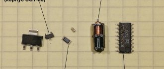
Second: preparing the engine
At this stage we will need three stepper motors from the drives. In the plastic extruder, we will use 1 NEMA 17-step motor , since we need sufficient power to move the plastic fiber. We will also need CNC electronics (RAMPS or RepRap Gen6/7). The choice of this component depends on whether you are satisfied with their cost and whether they are on sale at all. We will also need to prepare the power supply, cables, connectors, and heat-resistant tubes. You will need to solder wires to the stepper motors, and each of them must be located in its place (this is determined by the passport of a particular motor). Data sheets for CD/DVD stepper motors are presented here: https://robocup.idi.ntnu.no/wiki/images/c/c6/PL15S020.pdf, data sheets for NEMA 17 stepper motors can be found here https://www .pbclinear.com/Download/DataSheet/Stepper-Motor-Support-Document.pdf.
Required Tools
To assemble the components you will need:
- Screwdrivers.
- Spanners.
- Engraver for finishing elements.
Instead of screwdrivers, you can use a screwdriver. Tools (bits) must be of different sizes in order to tighten all the nuts and screws.
Main characteristics of SLM & DMLS
In SLM devices, a laser melts each layer of metal powder individually. Temperatures change dramatically, causing internal stresses to appear in parts. This may negatively affect the quality of the product, although in any case it will be higher than with casting. Products printed on SLM printers are superior to DLMS analogues in terms of safety margin and solidity.
When working using DLMS technology, internal stresses are not created, so the quality of products is disproportionately higher than that of analogues made by stamping or casting. This is especially in demand for the aerospace and automotive industries, as the components used in them must be extremely durable.
Extruder installation
After the table for the 3D printer is ready, the extruder is installed. Place two linear bearings on the middle linear rods. Check how far apart the axial bearings are from each other. Mark where they sit and where the holes should be. These holes are made using a drill. The linear bearings are secured with screws. Next, you need to mark the middle of the block from the linear bearings and make other mounting holes. Place the guide rods against the middle of the four holes. Move the extruder to secure the extruder in place. This design will allow it to be removed or upgraded in the future.
The extruder consists of a thermistor that measures temperature, a heating element and a head. The thermistor and heating element fit into the holes on the extruder head as shown in the figure. After completing the installation work, the electrical circuit of the extruder is connected.
Sixth: attention to electrical wiring
At this point, it's time to check the operation of the printer motors. To do this, we connect the computer to the controller via a USB cable, and the motors to the required pins. We launch Repetier Host and activate communication between the controller and the software via the serial port, which still needs to be selected. If the connection is made correctly, it will be possible to control the connection of the motors using manual control.
When using the printer, you need to be careful to ensure that the motors do not overheat, especially if the device will be used for too long. To do this, at the engine testing stage, you need to pay attention to adjusting the amount of current that will be supplied to the motor. This is an important procedure to avoid losing a step. To check, we connect only one motor corresponding to one axis. Then we will also check the remaining motors using a multimeter connected in series between the controller and the power source.
To do this, we connect only one motor, which corresponds to one axis. We will carry out the same operation for the two remaining engines. For this step, we need a multimeter that is connected in series between the power source and the controller, with the device set to current measurement mode.
Now we connect the controller to the computer, while measuring the current with a multimeter. After activating the motor through the Repetier interface, the current should increase by a certain amount, and the display of the measuring device will display information about the current of the operating stepper motor. The current must be determined for each axis motor and the values will vary. To set a value limit on each axis, we set up a small potentiometer for the stepper motor. The setting is carried out according to the following parameters:
- For the breakout board, set it to 80 mA.
- For the X and Y axes of the stepper motors, set the current to 200 mA.
- The Z axis requires more current, since it is along it that the carriage will move, which means more energy will be required. Here we set the current volume to 400 mA.
- For the extruder motor we set the current to 400 mA.
Software
The code that controls the printer must be loaded into the Arduino Mega board. The sketch is a G-code that is used in all CNC machines. To generate it, there is an automatic utility that itself calculates the necessary data according to the established parameters.
Template view of a G program:
%
O0003 (qewrtyu) (program number and name)
G00 Z0.7 (raising the tool to a safe height)
G00 X0 Y0 (tool moves to milling start point)
G01 Z-2 F60 (lowering the tool to the required milling depth)
G01 X0 Y200 F60 (1st side milling)
G01 X0 Y0 (2nd side milling, return to milling start point)
G00 Z0.7 (raising the tool to a safe height)
M30 (end of control program)
%
The sketch can be loaded through a programmer created using an SPI interface. Some Chinese analogues of Arduino contain a microcircuit (CH340 of various modifications), which is an SPI-USB converter. With its help, you can program the microcontroller on the board via a USB interface.
Tenth: testing time!
Now we can consider that the 3D printer is ready for the first test. In the extruder we use plastic fiber with a diameter of 1.75 mm. The choice of this material is not accidental: it is more flexible and ductile, therefore it is subject to pressing. In addition, such a thickness of fibers will require less energy during the printing process. We will use PLA plastic, which is a biological material, melts at lower temperatures, is environmentally friendly and easy to use.
Launch Repetier and activate Skeinforge profile slices. Let's try printing a small cube to check the calibration. It will print quickly, so you can immediately detect configuration problems or loss of motor steps after checking the actual size of the resulting cube. To start printing, open the STL model, cut the standard profile (or downloaded one) to see the object and the corresponding g-code. The extruder is heated, and after the melting temperature of the plastic is reached, we squeeze out a little material to make sure the system is working correctly.
Now we move the print head of the extruder to the origin of coordinates, while it should be as close as possible to the carriage, but not touch it. This will be the initial position of the head - from this moment you can begin the printing process on the 3D printer you created.
Z axis installation
Take the precast slab support block. Mark the block on both sides in the center, 2 cm from the longest edge. Make a hole with a drill. Secure all screws in the mounting holes with nuts. The fastenings must be rigid. Place the shaft connectors on the two remaining stepper motors and use a hex wrench to tighten them properly.
Place the screws on the other end of the coupling and tighten them again. Use Zip ties to secure the stepper motors to the bottom of the housing. Place the mounting plate support on the threaded screws and loosen the screws to lower the plate. Slide the top plates over the threaded connections to make sure everything is in place.
Table, springs, glass, end switches
The platform on which the 3D model will be located must have mandatory heating. Temperatures here reach 100 – 110 degrees Celsius, depending on the type of plastic.
The most affordable and time-tested option is MK2 measuring 214 x 214 mm. Don't forget to purchase springs for the table (you need 4 pieces). They make it much easier to set the nozzle level.
The top of the table is covered with ordinary glass 3-4 mm thick. Ideally, a mirror. Dimensions 200 x 200 mm with slight bevels on the edges for fastening screws. The asking price for a glazier is about 60 rubles; there is no point in bringing it from China.
Limit switches are special mechanical buttons that will limit the size of the table and “explain” to the electronics where the end of the printer’s working area is. As an option, inexpensive KW12-3. You need 3 pieces (one for each axis).
Hotend and plastic feed mechanism
This block is where the magic of 3D printing happens. Here a plastic rod is heated and squeezed through a miniature nozzle. I won't beat around the bush. An option that has been proven over the years is the V6 hotend version with a cooler, a 100k thermistor, a heating element, a radiator, and a Teflon tube. For example, this one.
It is better to take a metal one for the plastic feed mechanism (which will be mounted on one of the NEMA 17 motors). Firstly, it is more convenient to assemble, and secondly, skipping steps during printing is completely eliminated.