Among mechanical gyroscopes, the rotary gyroscope
- a rapidly rotating solid body, the axis of rotation of which is capable of changing orientation in space. In this case, the rotation speed of the gyroscope significantly exceeds the rotation speed of its rotation axis. The main property of such a gyroscope is the ability to maintain a constant direction of the rotation axis in space in the absence of the influence of moments of external forces on it.
Be sure to watch this video. This is a store-bought gyroscope:
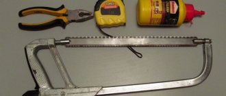
Yes, from the trash)) we will need - 1. a piece of laminate (found a scrap from my grandfather on the balcony), 2. The bottom and lid of a tin can (ate beans - got a can) 3. Steel stick (the most difficult part - found on the street) 4 .Plasticine (stolen from my sister) 5. Nuts or/and sinkers 6.two screws, a center punch (sharp thing at the end, an awl will do, everything from my grandfather) 6.wire (thick copper, found from my grandfather)) 7.Poxypol (or other hardening glue, taken from my grandfather)) 8. Electrical tape (ibid.)) 9. Threads (for starting and something else, from my grandmother)) as well as a saw, a screwdriver, etc.... the general idea is clear here
Next, we’ll cut out a frame from the laminate and bend the wire into a ring; we also need to punch an awl into the recess in the screws (I didn’t do it again, I just disassembled my gyroscope and took pictures of the parts...))
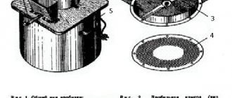
then we’ll assemble the main part - the rotor (or something else)) take the bottom and neck (they are the same) and make a hole in them (in the center!!) the hole should be as thick as an iron stick. We’ll cut the iron rod to length and sharpen the ends. If the alignment were better, insert the rod into the drill and, just like on a machine, sharpen it with a file on both sides; you also need to make a groove for winding with thread (you will find it in the photo)) we will spread plasticine on one of the disks, and stuff nuts and weights into it (who has a steel ring is absolutely gorgeous) then we connect both disks (sandwich) and pierce them through the holes with an axle. Lubricate the whole thing with poxy-pol, put it (the thing)) in a drill and while the poxy-pol cools, we will center the disk (so as not to hit) this is the most important part of the job. The balance must be perfect.
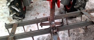
we assemble it according to the picture, the free movement of the rotor up and down should be minimal (you can feel it, but just a little), put a wire guard, attach it with a thread, and you’re done.
Instructions
- With these parts in hand, we can begin assembling the rotor. We punch holes exactly in the center of the can lids, preferably with the same nail as the one from which we will make the rotor axis. Next, using plasticine, we fasten the nuts on the lid, you can put more than six, the weight along the edge of the rotor will increase the time it rotates.
- Next we make the axis. To do this, secure the electric drill in a vice, tighten the nail without a head in it and sharpen it with a file. This way the axle sharpening will be located as close as possible to the center of the axle. It is necessary to sharpen on both sides.
- Without removing the sharpened axis from the drill, we will make a groove for the thread that will run the rotor. We attach the cover with nuts to the axle using glue, but do not use one that hardens too quickly. Poxipol works well. Coat the nuts with the same glue.
- Now the most important thing is balancing. While the glue is drying, you need to position the weights perfectly around the edge of the lid. We turn on the drill (vertically), if the rotating rotor hits in one direction, then some load is not positioned correctly. We fix it and try again. Lubricate the nuts on top and cover with the second lid. We glue electrical tape to the edges of the rotor. Let's dry it. The rotor itself is ready!
- We take two longer bolts, fasten them in a vice and punch holes in them in which the rotor will be fixed. Now we need to come up with an outer frame. Cut out a circle from the laminate. It is better to draw it with a compass in advance. Immediately draw vertical and horizontal lines at an angle of 90 degrees. Inside we cut out a smaller circle, but such that the rotor fits there. Along horizontal lines we make holes for the bolts opposite each other. We screw in the bolts. Between them we place the axis of our gyroscope. At the same time, you cannot tighten it too tightly, otherwise friction will dampen the rotation speed, and nothing will work. Leave about 1 mm of travel, but so that the gyroscope does not fall out of the bolts. We glue the bolts to the bar so that vibration does not unscrew them from the frame.
- All that remains is to install protection. Take a thick wire and bend it into a ring. At the location of the marked horizontal line we attach it to our product. The gyroscope is ready. We wind the thread around the axle and, sharply pulling it, check its functionality.
Homemade gyroscope
Gyroscope
(from ancient Greek yupo “circular rotation” and okopew “look”) - a rapidly rotating solid body, the basis of a device of the same name, capable of measuring changes in the orientation angles of the body associated with it relative to the inertial coordinate system, usually based on the law of conservation of torque (momentum).
The very name “gyroscope” and the working version of this device were invented in 1852 by the French scientist Jean Foucault.
rotary gyroscope
- a rapidly rotating solid body, the axis of rotation of which is capable of changing orientation in space. In this case, the rotation speed of the gyroscope significantly exceeds the rotation speed of its rotation axis. The main property of such a gyroscope is the ability to maintain a constant direction of the rotation axis in space in the absence of the influence of moments of external forces on it.
To make a gyroscope we will need:
1. A piece of laminate; 2. Bottom 2 pcs. from a tin can; 3. Steel stick; 4. Plasticine; 5. Nuts and/or weights; 6. Two screws; 7. Wire (thick copper); 8. Poxypol (or other hardening glue); 9. Electrical tape; 10. Threads (for starting and something else); 11. As well as tools: saw, screwdriver, core, etc...
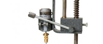
The general idea is clearly illustrated in the figure:
Let's get started:
1)
We take the laminate and cut out an 8-corner frame from it (in the photo it is 6-corner). Next, we drill 4 holes in it: 2 (at the ends) along the front, 2 across (the same at the ends), see photo. Now let's bend the wire into a ring (the diameter of the wire is approximately equal to the diameter of the frame). Let's take 2 screws (bolts) and punch holes in them at the ends with an awl or a core (at worst, you can drill them with a drill).
2)
You need to assemble the main part - the rotor. To do this, take two bottoms from a tin can and make a hole in them in the center. The hole in diameter should correspond to the axis-rod (which we will insert there). To make an axis-rod, take a nail or a long bolt and cut it to length; the ends must be sharpened. To make the alignment better, insert the rod into a drill and sharpen it, like on a machine, with a file or a whetstone on both sides. It would be nice to make a groove on it for winding with thread. We'll spread plasticine on one of the disks, and stuff nuts and weights into it (if you have steel rings, this is even better). Now we connect both disks (like a sandwich) and pierce them through the holes with an axis-rod. We lubricate the whole thing with Poxypol (or other glue), insert our rotor into the drill and while the Poxypol hardens, we will center the disk (this is the most important part of the work). The balance must be perfect.
3)
We assemble according to the picture, the free movement of the rotor up and down should be minimal (you can feel it, but just a little).
One day I watched a conversation between two friends, or rather girlfriends:
A: Oh, you know, I have a new smartphone, it even has a built-in gyroscope
B: Ah, yes, I also downloaded it for myself and installed the gyroscope for a month
A: Um, are you sure it’s a gyroscope?
B: Yes, a gyroscope for all zodiac signs.
To reduce the number of such dialogues in the world, we suggest finding out what a gyroscope is and how it works.
Mechanical rotary gyroscope from scrap materials
This homemade product will be interesting, first of all, to young children. Especially if you put it together. In general, making a rotary gyroscope from improvised materials is a great way to have fun and usefully spend your free time. Despite the visual complexity of the entire structure, it is very simple to make, because, in fact, a gyroscope is an ordinary top, only with a “secret”.
However, the very principle of operation of the gyroscope is also quite simple: the flywheel rotates clockwise around its axis, which, in turn, is connected to the ring and makes rotational movements in the horizontal plane. This ring is rigidly fixed in another ring that rotates around a third axis. That's the whole secret.
Manufacturing process of rotary mechanical gyroscope
We cut two rings of the same width from the plastic pipe. You will also need a bearing, which needs to be coated with superglue so that it does not rotate. We press a wooden “tablet” into the inner ring, in which you need to drill a hole in the center for a metal rod with pointed ends.
We put a piece of plastic tube on one edge of the rod (you can borrow it from a ballpoint pen). We drill two holes in the plastic ring for the rod and connect it to the rotating axis of the bearing using metal tubes of larger diameter (you can use sections of a telescopic antenna).
Then we put a second plastic ring on the main frame, having previously made small slits in it for a tighter “fit.” At the last stage, we glue weights for balance - steel balls - along the edges of the central axis. For a detailed process of assembling the gyroscope, watch the video on our website.
Rate this post
Source: https://sdelairukami.ru/mehanicheskij-rotornyj-giroskop-iz-podruchnyh-materialov/
Example for Raspberry Pi
As the brain for reading readings from the sensor, consider Raspberry Pi single-board computers, for example, Raspberry Pi 4.
Device diagram
Connect the gyroscope to the SDA and SCL pins of the I²C bus of the Raspberry Pi computer.
To quickly assemble and debug the device, take the Troyka Cap expansion board, which is placed on top of the raspberry using a sandwich method.
Software setup
Data output
We’ll leave writing example code for the Raspberry Pi as your homework.
Application of Arduino gyroscope based on mpu 6050 chip
Arduino is the most popular system for microcontrollers of the same name, allowing anyone, even without special education, to bring to life a project that they have long dreamed of. Whether it's an automated greenhouse or a simple system for turning off the lights when you hear a clap in a smart home.
But naturally, the microcontroller itself is not capable of performing all functions, and for this it is necessary to buy sensors for it, of which there are more than several dozen varieties on the market. We will talk about one of these, namely, we will look at the Arduino gyroscope. What it is, what projects it can be used in and how to configure it will be described below.
Programs
Without a program, the module will be nothing more than a pile of iron that will not perform a single function. Basic libraries for interacting with other MKs can be found on the official website or on the Internet, but in addition to them, you will need auxiliary code. With its help, you can configure the interaction between the accelerometer and the same Bluetooth module, without which, in most projects, it will become useless.
We will use a ready-made library for the Arduino MPU 6050, which was written by Jeff Rowberg.
In general, many people do it the other way, although not everyone knows how to program in C++, so a user who wants to write a program for working with a gyroscope has two options open to them:
- Find a ready-made template or library. This will only require a couple of seconds and an Internet connection, but do not forget that ready-made solutions are often written by equally inexperienced engineers. Therefore, if possible, check how high-quality the code you are downloading is. Look at reviews of the library, if possible, and try to download them on foreign forums. There will be more choice, and the likelihood of finding a really high-quality library is much higher.
- Write functions and methods for the system to work on your own. This option is suitable only for those who have previously dealt with the C++ language and understand all the nuances of working with Arduino. All the necessary auxiliary libraries can be downloaded on the Internet, and you can customize everything else to suit your needs. This method is ideal for those who want to implement their own project that has no analogues. Indeed, in this case, it will be extremely difficult to find prepared code for it, even if you are ready to edit most of it.
Assembly
Here everything depends on the interface you use, for example, for I2C from Arduino the contacts are useful: A4, A5, which are SDA and SCL inputs, respectively.
For the normal functioning of this entire system, it will be necessary to use the wire library in the code.
Also be prepared for the fact that the pinout may not be the best, so you shouldn’t make a body for the device end-to-end until you connect it and see the actual dimensions of your project.
Source
Board elements
Gyroscope on I3G4250D
The gyroscope is made on an I3G4250D chip and is a miniature motion sensor in three-dimensional space, developed using MEMS technology from STMicroelectronics. The default device address is 0x68, but can be changed to 0x69. For details, see the section changing the module address.
Voltage regulator
The NCP698SQ33T1G linear step-down voltage regulator provides power to the MEMS chip and other sensor components. Input voltage range from 3.3 to 5 volts. Output voltage 3.3V with maximum output current 150mA.
Logic level converter
The PCA9306DCT logic level converter is required to interface the sensor with different logic level voltages from 3.3 to 5 volts. In other words, the sensor is compatible with both 3.3 V boards, such as Raspberry Pi, and 5 V boards, such as Arduino Uno.
Troyka-contacts
The sensor is connected to the control electronics through two groups of Troyka contacts:
Accessories
This sensor or MK is created, depending on what you are going to purchase, from ATmega328 components.
Arduino MPU 6050 module pinout
Yes, it contains:
- 14 pieces of different pins and digital outputs, half of which are PWM outputs.
- Special quartz resonators with power up to 16 MHz.
- Built-in input for a USB cable, which will allow you to save not only time, but also money that you could spend on buying an adapter.
- Contacts and pinout for standard power supply with neutral, phase and ground.
- Factory reset pins, which will erase all machine code and data. This is useful if you mess up the program and the module turns into a useless pile of hardware, and just as a time saver if you need to change the firmware.
- ICSP pin, which is necessary in order to program the machine code that will be located inside the system.
All these components make up the Arduino gyroscope, allowing it to perform its basic functions. But how can you program the system if you have no previous experience working with MK data?
Testing
After debugging it is necessary to carry out testing. What is the difference? When testing, you know for sure that the program code works without lags and bugs, but you need to make sure that there are no logical errors in it.
With an accelerometer and gyroscope, the easiest way is to use 3D reading rendering programs, like ShowGY521Data, which will allow you to see in real time how the hardware is positioned in space. In case of malfunctions, you can always correct the zero level and reduce the sensitivity of the accelerometer, which also affects the final display model of the device.
Example for Espruino
As a brain for reading readings from a sensor, consider platforms from the Espruino series, for example, Iskra JS.
Device diagram
Connect the gyroscope to the power and I²C bus pins - SDA and SCL of the Iskra JS platform. For communication, use female-male connecting wires.
To quickly assemble and debug the device, take the Troyka Shield expansion board, which is placed on top of the Iskra JS using a sandwich method. For communication, use the three-wire “female-female” cable that comes with the sensor.
With Troyka Slot Shield you won't need any wires at all.
Data output
As an example, let's display in the console the angular velocity of the gyroscope around its own axes X, Y, Z.