Simple low-power “jammers” Radio and TV.
Sometimes it becomes necessary to create interference for TV and radio bands with a short range, which can drown out the image and sound signal. For example, you are tired of noisy neighbors with their loud TV or radio, and you want to calm down the “cause” of this noise a little. In this case, simple devices that are not difficult to assemble yourself using the diagrams below can be useful.
Ll and L2 are wound on a pencil, L1 - 6 turns, L2 - 4 turns, wire diameter 1-2 mm. It is better to take a transistor with a larger letter.
The setting is carried out by adjusting C2. Antenna length 0.5 -1m
The circuit on the K555LN1 MS can create “noise” of the signal if the receiver is located at a distance of no more than 5 meters from the interference source.
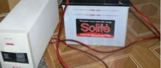
To implement the circuit, you need a 74LS04, K555LN1, KR1533LN1 or KR531LN1 microcircuit, any capacitor, and a battery. The antenna is replaced by a piece of copper wiring up to one meter long.
About the circuit: Pins 2 and 3, 4 and 5 must be soldered together. Solder a loop of wire between legs 1 and 6. It is better to make the connecting wires longer - there will be more interference. A capacitor can be made by twisting two pieces of wire together and adjusting it by holding your hand near it. Antenna - wire up to 1 meter.
Power supply – battery – 4.5-5V.
A circuit based on the transmitter proposed by M. Anisimov.
R1 - 750 Ohm. R2 - 240 Ohm. C1 - 5..25pf. C2 - 30pf. C3 - 10pf. C4 - 0.01 microns. VT1 - KT904A
L1 - 4 turns of PEV-1.0 on a 12mm mandrel, tap from the middle. L2 - 20 µH inductor, from a Chinese receiver. L3 - 8 turns of PEV-1.0 on an 8mm mandrel, L4 - 6 turns of the same wire and on the same mandrel (located between the 2 halves of L3). It should be noted that here you need a good power supply because... The current consumption is about 0.5A, so the batteries do not pass through.
The transistor must be installed on a good heatsink, otherwise it may simply burn out. The antenna is a rod about 1 m long.
Diagram of a simple device for jamming television broadcasts.
R1 — 3.3k, R2 — 1.5k, R3 — 1.5k C1 — 8. 30 pF (Trim capacitor) C2 — 5.1 pF C3 — 4.7 pF (5-10 pF), C4 — 27 pF (56-69 pF) VT1 — KT368 L1 - coil 4 turns of 0.5mm wire on a 6mm frame, Antenna 40 cm of copper wire Power - 3 Volts. The adjustment is made by a tuning capacitor and shifting and stretching the turns of coil L1.
A simple FM jammer The range of this device is small (only a few meters), but if you connect an antenna to the circuit, you will get a more serious device with an increased range.
L1 - 6 turns, diameter 9 mm
Setting: By rotating the screw of the tuning capacitor, we achieve adjustment of the device in the desired range. On the TV screen, it can cause interference in the form of stripes during the contour adjustment, and with fine tuning we will get a black screen. The sound from the TV or FM receiver disappears, being replaced by “silence” in the speakers.
Generator - interference on KT934 (instead of 934 you can use 911)
L1 - 2 turns 0.45 mm on a 4 mm mandrel L2, L5 - 16 turns PELSHO 0.3 - 0.4 mm on ferrite rings 8x4x2 L3 - 5 turns 0.45 mm on a 4 mm mandrel L4 - 2 turns 1 mm on 8 mm mandrel L6 - 3 turns of 0.45 mm on a 4 mm mandrel L7 - half a turn of 0.8 mm on a 4 mm mandrel L8 - 45 turns of 0.5 mm on a piece of internal insulation from coaxial, winding length 23 mm L9 - 4 turns 0.45 mm on a 4 mm mandrel, slightly stretched L10 - 1 turn of 1 mm on a 5 mm mandrel L11 - 23 turns of 0.5 mm on a piece of internal insulation from a coaxial cable, winding length 13 mm Transistor T1 without markings, case like KT368 Transistor TK on the radiator is like from the first stumps.
L2, L5 14W0.3 on a ring 10x6x4.5 M1500nn L3 5W0.4 D4 L4 2W 1.0 D8 L6 3W 0.4 D4 L7 0.5W 0.7 D4 L8 27W 0.3 D5 (11mm) L9 4W 0.4 STEP0.5 D4 L10 1W 1.0 D5
Use case: T1 BFR91A T2 2T610A without radiator T3 KT913B on radiator Coil data: L1 2W 0.4 D4
L11 17W 0.3 D5 (6mm) C7,C8 “CD” 2kB 0.022mf or any that can withstand the power. It is better not to install ordinary ceramics. The board is 1.5mm 2-way reverse side connected to ground near C5. R6 100 Ohm Rx *18 Ohm *connect between L8 and +power
Attention! MINIMUM safe Rx values are indicated; it is better not to reduce them. When you try to increase the collector current on the KT913 to 0.9A (1A according to the reference book), it fails. Test results: Supply voltage U=14.4V, I=0.7A RF voltage (Urf) at 50 Ohm load = 12V. With the antenna DISCONNECTED (the output is loaded with 50 Ohms, powered through a high-pass filter) within a radius of 5-7 m, the FM radio hisses throughout the entire range, a TV with an indoor antenna directed in the opposite direction barely catches 3 UHF channels, the LPD radio station opens the noise suppressor. When connecting a piece of 1m wire within a radius of 15-25m (I didn’t check further), the FM radio and MF are completely jammed, 2 UHF channels (the most durable) are received on an external antenna 1 floor above with strong interference.
Manufacturing nuances, setup
Resistors with capacitors can be manufactured using current mirrors, as well as similar replaceable elements.
This substitution will reduce not only the size of the gadget, but also its cost. An important nuance is the setting that allows you to eliminate problems associated with jamming other signals. To eliminate frequency mixing, it is necessary to adjust the existing inductor, on which the outgoing frequency directly depends. This action occurs due to a change in the number of turns placed on the core.
Further, the instructions for creating a jammer for inexperienced craftsmen provide a device for the functioning of the amplifier. This device shows the increase and decrease of the signal, which is not always effective during operation of the device. In some cases, it is desirable to minimize the gain percentage, thereby reducing interference.
Adjusting this indicator consists of experimentally adjusting the required amplifier manually, while simultaneously checking the functioning of the complex as a whole and its effect on the tracking device.
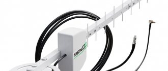
An element such as an antenna does not need tuning, but you should choose it as seriously as possible. According to reviews from radio amateurs, it is best to equip an SMA antenna, from which the signal goes in different directions and which is characterized by the highest gain.
A communication signal jammer can be created with your own hands from other types of transmitting elements:
- whip type antenna;
- panel type;
- log-periodic.
Depending on the coverage area, a choice appears that is related to the number of antennas to be equipped. If it is necessary to obtain a finished result within a few meters, 1 part is used, while up to 4 parts are installed in individual structures.
Hmm, is this a new design? Or did he just not know something?
Adequate people don't make noise all the time at night. They don't even need an explanation. Therefore, I think that talking with them is a waste of time; taking action right away.
Annihilator, Tuesday. At two o'clock in the morning. At full volume. “I want you 360” Usually an anonymous call to the police helps a lot, the drive takes about 15 minutes. But they are effective.
This is not a neighbor in the picture, but the owner’s son