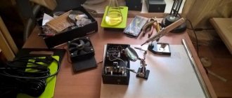
I have long wanted to assemble a music center with my own hands. I read the forums, looked at people, and I really liked the idea of making music for the home from a car radio and car speakers. Moreover, knowledgeable people argued that even from an inexpensive radio you can achieve much better sound quality than from a music center for the same cost. The sound source was “Mystery”, the entire system was powered by a 300w power supply from a computer. (There are many on the Internet circuits) Well, the speakers are the cheapest, from Auchan. The antenna is from there. The body consists of furniture parts. The holes for the speakers were sawed with a jigsaw, for the phase inverters - with crowns. The covers for the bass reflexes are grommets for curtains. Everything was attached with Euroscrews, IMHO this is the best way of fastening for oversized things. The inside was sealed with sealant.
Tools and materials
For models assembled from scratch, use:
- set of speakers for a stereo system;
- ready-made mp3 player;
- ready-made radio receiver (it is advisable to choose a professional model);
- computer (or homemade) power supply;
- a ready-made pre-amplifier with an equalizer (a device from any musical equipment is suitable, for example: an electric guitar, a DJ sampler, a mixer, etc.);
- radio components for the amplifier - according to the selected circuit;
- cooling radiators or fans for the amplifier;
- enamel wire for filters of multi-way speakers;
- network cable ShVVP (2*0.75 sq. mm.);
- non-flammable cable KSPV (KSSV, 4*0.5 or 2*0.5);
- 3.5-jack connectors for connecting speakers.
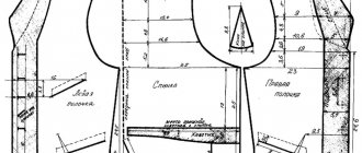
A passive speaker - usually a subwoofer - that can be easily disassembled and rebuilt, perhaps replacing the top, bottom and side walls with longer ones, is suitable as a finished enclosure. Refer to the drawing. It will be difficult to install an amplifier and power supply in the “satellites” (high-frequency speakers) - a radiator or cooling fans will take up a lot of space. If the center is small, use the housing and supporting structures from the car radio. For a self-made case you need:
- chipboard, MDF or natural wood (the latter option is most preferable - unlike MDF, where there are often voids);
- furniture corners - will make the structure easily disassembled;
- sealant or plasticine - eliminates cracks, making the structure impenetrable to the air pressure produced by the speaker;
- damping material for speakers – eliminates the resonance effect;
- epoxy glue or “Moment-1”;
- anti-mold impregnation, waterproof varnish and decorative paint;
- self-tapping screws, bolts and nuts, washers of suitable sizes;
- rosin, soldering flux and solder for a soldering iron.
Instead of paint, you can also use decorative film. Tools you will need:
- a classic installer's set (drill, grinder and screwdriver), a set of drills and a cutting disc for wood, a grinding disc for metal and a set of bits included;
- a mechanic's kit (hammer, pliers, side cutters, flat and figured screwdrivers, a hacksaw), you may also need hexagons of different sizes;
- To make sawing easier and faster, you will also need a jigsaw;
- soldering iron - it is advisable to use a device with a power of no more than 40 W; for the safety of the work being carried out, you will need a stand for it;
- sandpaper – needed in places where you can’t get to it with a grinder.
It is ideal if the home craftsman has a lathe. It will help to perfectly produce any rotating elements.
How to do it yourself?
You will need it.
- Soldering iron, solder and rosin, soldering flux. Instead of the latter, zinc chloride was previously used - it is prepared from tablets containing hydrochloric acid. These tablets are used by stomach patients. The source of zinc is any alkaline (salt) battery that has exhausted its service life: its “glass” is made of zinc.
- Copper wire is a thick winding wire. An alternative is to twist all sorts of thinner stranded wires. For strength and reliability, they are soldered with solder so that the copper does not oxidize and the conductor does not “unravel.”
- Dielectric base. It can be any board, plywood, chipboard, fiberboard, as well as homemade or industrial getinax (or fiberglass), from which the printed tracks have been removed. You can also use flat pieces of plastic from old, outdated electrical appliances.
- Fasteners Bolts, screws, self-tapping screws, lock washers, nuts. Stock up on the right amount of them. Perhaps plastic “mounts” will also come in handy.
- Coaxial cable (with a characteristic impedance of 50 or 75 ohms), plug (for the antenna jack of your receiving device).
- The simplest locksmith tools. This can be a flat and figured screwdriver, pliers, side cutters, hacksaws for metal and wood, possibly an adjustable wrench and a hammer. An angle grinder and a drill will also speed up the antenna manufacturing process.
- Waterproof varnish or paint. The conductors and the place where the cable is connected to them must be painted. This will protect them from corrosion caused by drops of water.
If you are not a radio specialist, then take a ready-made drawing. An example is a loop antenna. To make it, do the following.
- Based on the dimensions from the drawing, bend a working element – a “butterfly” – from copper wire.
- Place it on a strong dielectric base, tying it to a wooden or plastic plate using “mounts”. A more “advanced” option is vertical stands on the edges and on a screw fastening. This is what “homemade workers” did in the 1990s, making antennas for receiving UHF television channels.
- Solder the cable. The central core is connected to one side of the antenna, the braid to the other. There should be a gap of up to 1 cm between the parts of the figure eight and them. The dipole antenna is connected to the cable in the same way.
- Paint the entire structure.
- After the paint has dried, secure the structure to a pole or pipe. Tie the cable in several places to the support.
- Attach the plug to the other end of the cable and raise the antenna higher. Point it at the broadcast city. If the distance is too great, there is no direct signal - they find a reflected one, for example, from a mountain or the tallest building not far from you.
The antenna is checked based on the reception quality of the desired radio station. Radio transmitters today are located in random cities and regional centers - many private radio broadcasters have appeared, making money from advertising. Radio stations are not located in the location of the city television tower (on the “telecenter” hill), but on a low mast about 30 m high. Not everyone wants to rent the “strategic height” of a city or region, broadcasting from the roof of a 9 ... 25-story building through a low-power (up to 100 W) FM transmitter.
There should be as little noise as possible in the background of the radio transmission. Radio reception must be in stereo format. It is impossible to receive a stereo transmission when the signal is weak - noticeable noise appears in its background. Rotate the antenna until you get the best quality. If the station is too far away and the noise remains, connect the radio amplifier to the cable break, next to the antenna.
A universal cable will help here, in which, in addition to the “coaxial”, a pair of additional wires are hidden under the outer protective sheath. The power line is isolated from the central conductor by the braid of the main radio cable. If there is no such cable, the amplifier’s power is supplied through wires to the radio receiver nearby, separately.
You can find out how to make an FM antenna with your own hands in 15 minutes below.
Device testing
To test the music center, you must first load the audio file onto a portable storage device with a USB output. After this, turn on the music center to the mains voltage. An indicator should light up confirming that it is turned on.
Then insert the flash drive into the desired USB port. If all steps were performed correctly, the speakers should play sound. If there is no sound, turn up the volume or check the connections of all contacts.
So, I didn’t make the whole body, I just used part of the table, but made something like a casing with cardboard and colored tape.
I installed an 80 mm fan from a computer power supply there and bought 2 car switches with bulbs of different colors.
One turns on the power supply to the fan, and the other turns on the backlight for the color music system, which I recently assembled.
The fan is connected through a simple transistor voltage regulator, which can be used to regulate the speed of rotation of the blades - after all, we don’t always need 100 percent of the revolutions. Its diagram is in the figure below:
The regulator is made as a canopy, directly on the variable resistor itself. I screwed a piece of aluminum onto the transistor just in case. Although it practically does not heat up.
Why did you use cardboard? It is good because it is perfectly cut and takes any necessary shape, the switches are of excellent steel, and cooling is ensured.
Power supply – switching, 12V 4A. Its power is quite enough to power the entire system.
And all this equipment is connected to a surge protector.
Total system costs:
Power supply 700 rubles - 12 volts 4 A - radio 900 rubles together with a power filter, casing and all wiring. - speakers - 2 sets of Mystery MJ103BX speakers 800 RUBLES each - 1600 rubles with my discount 1500 rubles - two switches with 12 volt indication – 45 rubles. - fan regulator and transistor, tape, electrical tape and other consumables were already in stock.
In your version, you can use textolite, aluminum or plywood for the body (placing the radio inside the old speaker). The main thing is that I showed you the very principle of constructing such devices. The design of the homemade music center has been installed and has been pleasing with its convenience and good performance for many days now! Comrade was with you. redmoon.
Discuss the article HOW TO MAKE A MUSIC CENTER
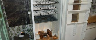
A music center can be built from an old cassette media center. With due diligence, you will get a functional and completely modern device. The process of creating a device with your own hands will require imagination, a set of tools and a little experience in working with electrical engineering.
You can create a homemade music center from an old car radio. Most of these devices have a powerful amplifier in the electrical circuit, which allows:
- Reproduce sound using suitable passive acoustics left over from an old tape recorder or player.
- Depending on the complexity of the device, play CDs, including in digital formats.
- Install a radio whose antenna can be mounted inside the speaker.
The photo shows an example of a homemade music center. In fact, this is the basis, which can then be brought to the desired level: create finishes, design the body, use computer modding tools.
Another way is to make a music center from an old player or tape recorder, using almost all the components of the donor device.
The radio can be disassembled and its electronic components can be placed inside the body of the old media center. Such work is not difficult: the design already contains an antenna and a power supply, which are often standardized and do not require modification.
You can place an old radio in place of cassette decks
not used due to outdated storage media.
For the above options, the power source can also literally be “lying under your feet.” Worn out, unusable due to a drop in power or slight deviations in parameters, computer power supplies are an ideal option.
The comb, which attaches to the motherboard, contains pins for system startup and a low-power, fixed-voltage bus. To connect to a 220V network, the computer unit has enough four-pin connectors.
Remaking an old model of a music center for USB
The use of analogue audio systems has become a thing of the past with the development of digital technology, but many people still have fully working tape recorders, stereo systems and cassette players at home. Such outdated equipment can be modernized using a built-in module. Converting the music center to USB allows you to make it read mp3 recordings and other types of audio files. This relatively simple process does not take much time and does not require special skills and knowledge when using special modules.
What are embedded audio modules
To quickly modernize an old music center, you should use a special built-in audio module - a sound converter. You can make such a device yourself, but making a homemade module will require a significant investment of time and special knowledge in the field of electrical engineering and electronics. It is much easier to buy finished products, presented in a wide range by Chinese manufacturers.
Purchased audio modules have a digital-to-analog conversion function. Some models are additionally equipped with mini sound amplifiers. More expensive devices are equipped with an LCD display, Bluetooth, remote control and additional connectors.
In terms of their functionality, the modules are like a compact mp3 player that does not have its own power supply and speakers. It is to fill these missing devices that the old audio system will be used.
To remodel, you will need a music center that still has the following components in working order:
- battery pack;
- speakers;
- sound amplifier.
Algorithm for embedding a module into a music center
To integrate a purchased module into an audio system, you must correctly determine the location of its installation. When choosing the location of this node, you must also take into account the possibility of remote control of the created music system using the remote control.
To convert an old music player into a flash drive, you need to follow the following algorithm of actions.
- It is necessary to partially disassemble the old tape recorder.
- Based on the diagrams of the module and audio system, you need to connect the power supply to the corresponding pin of the modular board using a wire.
- Then you should proceed to installing the module in the selected location: the compartment for cassettes or disks. To do this, you need to connect the corresponding outputs of the modular device and the sound card of the music center. The procedure can be performed using a soldering iron (soldering wires) or using the existing aux input.
- At the end of the upgrade, you need to connect the power supply and the upgrade is complete.
When choosing a different location for mounting the USB connector, you should make a hole in the case for it. In this case, you can bring the port for the flash drive to the rear panel of the tape recorder.
Module and center diagrams are usually included with purchased devices, otherwise they can be easily found on the Internet. The audio module must have a constant power supply of 5 V. From 12 volts it will need to be connected via a power supply (12-5 V). All remodeling work must be carried out in compliance with safety regulations.
Such homemade players can be used as portable ones: it is much easier to transport a small music center around the house than a desktop computer. You can make a miniature (micro) music center with USB from an old cassette player.
All the subtleties of the alteration are shown in detail in the video below.
Conclusion
The self-made device has limited functionality, however, it copes well with the task of simply playing sound files. Such a refurbishment does not cost much money and will allow you to give a second life to your favorite equipment - outdated music centers, for example, Sony, Aiwa, Panasonic. If you have the desire and free time, you can continue to improve the old equipment in the same direction as long as the original speakers and built-in amplifier work.
Article added: May 16, 2022 at 11:39
Electrical connection diagram
Although most radio tape recorders have a different number of outputs and inputs, it is not difficult to find a method for connecting them to a 220 Volt network when making a home audio system. The standard electrical diagram for connecting cables looks like this:
To power the system, a regular power supply from an old PC is used. Before connecting it to the system, you need to check that the device has enough power to receive 5 amps.
Required connectors for connection:
ATX type power supplies must be connected via control connectors. They are on a 24-pin comb.
The image shows which wires need to be connected to the car radio.
The back of the device looks like this:
For different types of radios, the location of the power supply, the number of sound outputs and other parameters may differ. Only the color designations of the cables do not change.
Electrical connection diagram
Although radio tape recorders have a different number of output channels and different connection interfaces, finding a way to connect them to a 220 V network when creating a music center is not difficult. The general switching diagram looks like this:
A computer power supply will be used as a battery. When choosing it, you need to make sure that the device is powerful enough to output 5A. Required contacts for connection:
ATX format power supplies will have to be started through a control pair of contacts. It is located on a 24-pin comb:
In the figure of the switching diagram it is already marked which of the connector cables should be connected to the radio. The back of the sound-reproducing device may look like this:
Depending on the model, the location of the power supply, the number of audio outputs and the set of other interfaces may vary. Only the color marking of the block remains unchanged. The instructions for the radio will help you determine the purpose of a particular wire.
Non-standard paths
Home craftsmen who do not have such a ready-made solution as a car radio can safely use their imagination. There are a lot of options:
- The power supply can be a computer power supply or a switching power supply suitable for power and voltage: from household appliances, mobile phones.
- Computer drives with audio output are suitable. Such a device is usually equipped with a start button, which also serves to go to the next track; double-clicking it stops it. Some older drives, such as the Creative brand, are equipped with a full set of control keys, as well as a volume control on the front panel.
- Do you want to listen to the radio? A small radio the size of a matchbox, receiving a signal from a retractable antenna, will sound perfectly high quality.
- There are no problems with digital formats either. An inexpensive FM transmitter paired with the already mentioned tiny receiver is an ideal tool for obtaining high-quality sound.
- For the truly lazy, there is an ideal donor - an old but working electronic alarm clock. Chinese models easily act as radios and read digital formats from memory cards.
You won't have to do much to fit all of these devices into your old media center. The devices need to be freed from their cases, maybe a little work with a soldering iron to bring the control buttons, slots for memory cards and USB to the front plastic panel of the center. The answer to the question of how to make a power supply circuit becomes clear if you count the number of outputs in a computer power source - there are enough of them for everyone.
Connection via a stationary power supply
Since multimedia systems for cars operate on 12 V, they do not require the use of more powerful power sources to operate. Therefore, many craftsmen connect the radio to an uninterruptible power supply and various network adapters.
Which power supply to choose
To determine which power supply for the car radio is needed, it is important to evaluate the output current. It should be at least 5 A. With increasing loads, consumption can increase to 10-15 A.
Professional devices with increased power reserves are available on the market, but due to their high cost they are not in demand. It is better to choose a simple but high-quality power supply with optimal operating parameters.
Connecting the radio
If you are going to connect the radio through a computer or laptop unit, you need to cut off the base connector of the device through which it is connected to the vehicle, and strip the ends of the wires to connect to the network adapter or uninterruptible power supply. The wiring is left in the old connectors, after which the acoustic circuit is assembled according to the basic circuit.
The role of the battery is performed by an uninterruptible power supply or an adapter with an output voltage of 12 W.
Instructions for creating a music center from a car radio
You need a power supply to create a music center. But it doesn't have to be new. If you have an old computer, unplug it and use it for your project.
- To get started with your home stereo system, locate the green and black wires on the block and place a piece of wire between them to act as a jumper wire.
- On the car stereo, twist the red and yellow cables together.
- Next, connect the black ground wire on the stereo to the black wire on the connector.
- The red and yellow wires of the stereo connect to the yellow wire of the connector.
- Then follow the usual instructions to connect the stereo to your speakers.
While using a power supply to power your car stereo in your home is one way, you can do it even if you don't have a unit.
- You can connect the speakers to the radio using the gray and green wires.
- You may need to use an additional speaker cable.
- The next step is to connect the yellow and red wires on the stereo and add an additional speaker for stereo sound.
- Connect the wires with soldering or electrical tape to get a quality result.
- You need a 12V power cord to connect the device to the network. You can easily purchase it at any technical store.
- Cut the end of the power cord and connect the black wire to a line of white around the red and yellow stereo wires.
Electrical connection diagram
Although radio tape recorders have a different number of output channels and different connection interfaces, finding a way to connect them to a 220 V network when creating a music center is not difficult. The general switching diagram looks like this:
A computer power supply will be used as a battery. When choosing it, you need to make sure that the device is powerful enough to output 5A. Required contacts for connection:
ATX format power supplies will have to be started through a control pair of contacts. It is located on a 24-pin comb:
In the figure of the switching diagram it is already marked which of the connector cables should be connected to the radio. The back of the sound-reproducing device may look like this:
Depending on the model, the location of the power supply, the number of audio outputs and the set of other interfaces may vary. Only the color marking of the block remains unchanged. The instructions for the radio will help you determine the purpose of a particular wire.
Selecting a car radio
Since by default, to create a homemade one, we will use a device lying around idle, any car radio will suit us. But this “any” should still have a minimum set of functions:
- At least two-channel output with a power of 40 W each;
- Tuner;
- CD/DVD/MP3 disc player;
- USB – connector for reading information from flash drives.
In addition, you should pay attention to the sound card of the device itself. Some radios can even surpass most modern music centers in terms of purity and sound quality. And although, due to the fact that the car radio does not have large and capacitive capacitors in its “arsenal”, due to which it loses in the reproduction of low frequencies to powerful stationary speaker systems, it is definitely at its best in the reproduction of the high-frequency range
Another definite advantage of the car radio is the presence of a multi-stage frequency-separated equalizer, while most stationary music centers are equipped with only standard presets
And although, due to the fact that the car radio does not have large and capacitive capacitors in its “arsenal”, due to which it loses in the reproduction of low frequencies to powerful stationary acoustic systems, it is definitely at its best in the reproduction of the high-frequency range. Another definite advantage of the car radio is the presence of a multi-stage frequency-separate equalizer, while most stationary music centers are equipped with only standard presets.
How to turn on via a step-down transformer
A simple rectifier on a step-down transformer from a 220 V network
The implementation of this option is more difficult, but for those who love to tinker, it will not be difficult. We won’t tell you how to wind a transformer. We assume that you already have it and with the necessary parameters. Namely:
- input voltage 220–230 V, output - 12 V;
- power - from 120 watts depending on the audio system;
- current up to 10 A.
At its output we will have 12 V AC, and the car radio is powered by DC. Therefore, this tension must be straightened. You can assemble an elementary circuit using a diode bridge and a capacitor.
Diodes, for example, KD226, it is better to set the capacitor at 4700 μF to reduce ripple. Before connecting, check the output voltage parameters. Without load it can be slightly higher and amount to 14 - 15 volts.
How to make your own sound amplifier for a radio on a chip
Some older car radios do not have such useful inputs as USB and AUX, so to use them as an amplifier you will have to remove the device from its seat and open the printed circuit board. If you have no experience working with electronic circuits, then you should not take on this work. First, you need to find a low-frequency amplifier integrated circuit on the car radio board. This is a large part and the only one that is installed on the heat sink. On the circuit diagram and on the board it may be designated AMP or POWER AMP. Next you need to determine the input pins of the amplifier. There are two of them on the chip - the left channel input and the right channel input. The left channel can be designated Line L or L-in, and the right channel – Line R or R-in. You can determine correctness by touching each contact with your finger. A hum will be heard from the corresponding speakers. In this case, the power of the car radio must be turned on. The ground or common wire is marked with Line GND.
If there are no markings on the diagram, you can find the channel inputs directly on the chip. To do this, you need to sequentially touch all the terminals, focusing on the appearance of hum in the speakers. You cannot solder the connector to these contacts. It is necessary to determine the connection points for the coupling capacitors and solder the wires to them.
The wiring of channels on the plug and socket must be done using shielded wire according to the following diagram.
A homemade sound amplifier from a radio can be used with any external sound source. There are no tone controls in this design, since the signal is fed directly to the input of the final amplifier, bypassing the equalizer. In order to reduce the noise level, you should cut off the tracks going to capacitors C1 and C2 from the pre-amplifier of the playback head.
If your car has a new radio, you can make a compact audio amplifier from the old one. To assemble a sound amplifier from a radio, you need to remove everything superfluous and unnecessary.
How to assemble a sound amplifier from a radio can be understood from the figure. The ZXM8330-PA car radio is assembled on two microcircuits and three transistors. The FM tuner is assembled on a TA2003 chip, and the final amplifier is built on a TDA2003 chip. The radio receiving part and the first transistor in the stage of pre-amplification of the signal from the magnetic head can be immediately eliminated. The power supply wire to the electric motor also needs to be cut. The printed track of the tuner power supply, coming from the “Radio” - “Tape” switch, and the track from the output of the microcircuit to the collector of the second transistor are also cut. You can experiment with the remaining elements of the circuit. If the external device that will be connected to the amplifier has a sufficiently powerful output signal, then it should be connected to the upper terminal of the variable resistor “VOLUME” in the circuit.
To supply a weak signal, you can use the collector of the second transistor, that is, the point where the signal was supplied from the tuner. In this case, the tone controls and the volume limit switch “Mute” will work. The power supply circuit of the first and second transistors must be broken. In a car, all electronics are powered by a battery. If the amplifier is to be used as a standalone device, it will require a simple 12-18 V power supply. The amplifier provides an output power of 6 W on a 4 ohm speaker and 10 W on a two ohm speaker. The maximum current consumption is 3.5 A. Using a similar principle, you can make an amplifier with your own hands from any car radio. The main thing is to correctly identify the input circuits and disconnect from the input all unnecessary stages that may be sources of noise. This is especially true for the amplification stages of the playback path. Working with stereo systems is a little more complicated, but the technique remains the same.
How to make a radio receiver body with your own hands
I decided to make the body from pieces - scraps of OSB boards. The blanks were cut with a jigsaw.
1. The receiver will require six blanks:
— front panel frame for mounting a car radio measuring 260mm×95mm;
— front panel for speaker 260mm×240mm;
- side wall, height 330mm, base 240mm, top 260mm, two pieces required;
— top cover 262mm×260mm;
— bottom cover 230mm×260mm.
The external dimensions of the radio receiver box are as follows: width 275mm, height 330mm, depth 260mm. Sanded the blanks from the front side
emery cloth.
2. The issue of final finishing of the receiver has not yet been resolved, so for freedom of thought I decided to assemble the case using PVA glue. We begin the assembly from the base of the receiver; to do this, in the place where the side walls are attached, we use self-tapping screws and glue to attach two slats with a cross-section of 25mm×25mm.
3. I glued the same bars in the places where the side walls of the top cover were attached; here I did not use self-tapping screws; I applied clamping force for gluing using clamps. Drying time for each glue is 24 hours.
4. I glued the side walls to the bottom and lid. We press the walls against the slats with clamps. Be sure to check the diagonals of the box, the measurements should be the same. If something is crooked, it’s better to fix everything at this stage.
5. After the gluing of the box had dried, I glued the slats along the contour of the fastening of the future back cover, and also glued the slats in the places where the front panels were installed. I used clamps for fixation.
6. Carefully marked and cut out a cutout on the radio mounting panel in the center of the upper part, 178mm wide and 50mm deep.
7. In the center of the speaker panel, I drilled a hole with a diameter of 113 mm for the speaker. You can use old working ones or other loudspeakers as a speaker. You can immediately drill the mounting holes. An unpaired speaker, left over from the published design, is installed in this design.
8. Before installing the panels, be sure to sand their front part with sandpaper, then it will be more difficult to do this.
9. Glue the panels into the box. Finally dry all connections.
10. Sanded the box from the ends and from the adhesive joints.
11. The box must be thoroughly cleaned of dust.
12. I cut the back wall with dimensions 320mm×270mm from a piece of treated fiberboard. I drilled holes with a diameter of 10mm in the wall according to the markings. The wall is attached to the body with four self-tapping screws.
13. The receiver body can be covered with parquet varnish, puttied and painted or covered with veneer.
Creating a home speaker system
So, the essence of the issue is clear to us. A car radio with speakers (see How to choose speakers for a car radio on your own) have been lying nearby on the table for a long time and are “asking for battle.” Now we are the only ones who don’t understand how we can “connect” 12-volt equipment with a 220-volt alternating network? I must tell you that this problem has several solutions, which are contained in the instructions below on how to connect a car radio from a 220 network.
Method one: connection via a homemade step-down transformer
This method is the most complex and time-consuming
Although the level of modern electronic technology allows us to completely abandon it, due to the fact that we are considering all the ways on how to connect car radios to 220 V, we will still pay due attention to it
Preparation
So, before connecting the car radio to the 220 network, we will have to create a transformer that steps down to 12 volts with our own hands. Why do we need:
- A similar (see photo) transformer that converts the standard network voltage to a lower one (in our case, 36 volts);
- Insulating material;
- Wire of suitable cross-section and length;
- Multimeter/voltmeter;
- A calculator, although the calculations are not at all complicated, you can get by with a piece of paper and a pen.
Step-down transformer 220/36 Volt
Creation
In order to make the task as easy as possible and not disassemble the transformer winding itself, we use the free space of the magnetic core area. We wrap the free area of the magnetic circuit with insulating material and wind a piece of the wire of our choice onto it of any length. Let's say we got seven turns. In order to calculate the number of turns and wire length required to reduce the voltage, we need to perform the following procedures:
We assemble a circuit for switching on a transformer using a piece of wire wound around a magnetic conductor and measure the output voltage;
We take readings from seven turns of wire
- The multimeter gave a value of 2.9 volts. This means that we have 0.41 volts per turn of the secondary winding. From this ratio we obtain the number of turns required for an output of 12 volts: divide 12 by 0.41 and get 30 turns;
- We measure the length of the wire spent on the experimental seven turns, we get 126 centimeters. That is, there are 18 centimeters per turn (126 divided by 7), which means that for 30 turns we will need 540 centimeters of wire.
- Next, we wind this whole “thing” onto a magnetic circuit, assemble the circuit and check our calculations with a multimeter.
What to connect where in the car radio
Output blocks on radios can vary in size and wire layout. The good news is that manufacturers try to adhere to certain rules in choosing colors for each system. And you can take advantage of this.
Connectors on radios
Most often, the colors of the wires for each of the systems are as follows:
- Yellow and red - 12 volt power supply. Yellow - from the battery, red - from the ignition, this is control.
- White, purple, green and gray (and their variants with black or white stripes) - for the audio system.
- Black is mass.
- Blue - antenna output.
The colors of the audio system connection wires may vary slightly. But for food and weight these will be the colors.
A standard connection diagram that makes it easy to understand what needs to go where
We will deal with power supply further, and in this connector we will talk about connecting the audio system and antenna. With the antenna everything is simple - blue wire. Temporarily you can “hang” here even just a piece of wire, or you can use a purchased or homemade antenna .
An audio system is rarely complex. Most often they install one or two columns. We connect them to any pair of wires from the list. A pair is lilac and lilac-black or lilac and white, for example.
The primary color indicates that this pin is positive, "+". A white or black stripe indicates that the output is negative “-“. This must be taken into account when connecting speakers. They will definitely indicate the plus and minus of the connection.
We connect one of the wires of the pair to one input of the speaker, the second to the other. After power is applied, sound will appear in the speakers.
How best to connect wires
Depending on the condition in which you received the car radio, it may have an output block, or it may have a bundle of wires. Both options are workable. The second option is preferable, as it is easier to make a high-quality connection. If you no longer plan to use this device in your car, it is easier to cut off the ISO block. Well, or those wires that need to be cut off from the block.
Connecting wires when connecting a car radio
If you decide to keep the block, when connecting, we strip the conductors and insert them into the sockets opposite the wires of the desired color. If you chose the “wires without block” option, the ends of the required conductors must be stripped of insulation (0.8-1.0 cm). Then, during operation, the connected wires are twisted tightly. If you have a soldering iron, it is better to solder all the twists after testing - when you are sure that everything works.
When they are convinced that the radio is working, the connections are isolated. You can use electrical tape, but it is safer to use heat shrink tubing.
POWERFUL AMPLIFIER FOR BEGINNERS
I highly recommend that beginners assemble this circuit. I am not a master myself, but rather a beginner radio amateur. Well, I already know the basics of electronics, basic things, so I decided to try my hand at this design... It all started with the fact that I had long wanted to build myself an inexpensive, but quite powerful sound amplifier. Not on the simplest 1555, which play no better than ordinary mini-speakers, but at least by fifty watts. Well, I've reached my goal. I assembled an amplifier using the well-known TDA7294 microcircuit. You can easily squeeze out 100 W or more from it. I bought the microcircuit for only $1.5, and took everything else from a Soviet TV, I found almost everything there.
Microcircuit connection diagram
The advantage of this amplifier is that it is so tested and retested by thousands of radio amateurs that all beginners can assemble this circuit without any problems - there are no serious obstacles here. All parts can be found at home (except for the chip itself).
It is permissible to take the TS-160 power transformer from the same TV, disassemble it, leave the primary, and wind the secondary with 172 turns of wire with a diameter of 1.5 mm. Low-power transformers are not suitable here (after all, you need 200 watts just for sound). The minimum power of the transformer must be over 100 watts if the microcircuit is powered by reduced voltage. It is known that the power supply of the 7294 microcircuit is bipolar. The voltage was -+ 55 volts. Current 2-3 Amperes. To be honest, I didn’t measure the current consumption, that is, I forgot. I remembered when everything was soldered. The power wires need to be thicker. At high volume, thin wires heat up and stick to each other, which actually causes a short circuit.
The diode bridge was taken from an imported TV, although the diodes got noticeably hot when playing sound. All other details were obtained from Soviet TV.
One more thing, the amplifier is equipped with a cooler, since the radiator was not very large. I assembled the diagram on a piece of cardboard. I didn’t find any textolite at all. For many radio amateurs, such luxuries as textolite, vitriol, and a laser printer are not available. I’m also on this list :( But you can see that if you want to do something, you can get by with little.
The parts were connected with copper wires. I didn’t install LEDs or other indicators at all, since seriousness and performance are important to me in the first place. The speaker is currently 20-30 W, 8 Ohm. I haven't bought the 100 watt head yet.
Photo of the finished amplifier is above. Yes, accuracy is not in the best condition. But surprisingly, everything turned out very well - there are no audible distortions. The input signal was supplied from the telephone. The amplifier started up the first time it was turned on and that made me very happy! With uv. best.boy99 UMZCH Forum
Radio pinout
To connect a car radio, more than one conductor is required. In addition to power, you need to connect speakers (in most cases from 2 to 4), control signals, etc. All connection points are output to a connector, which for a long time each manufacturer made at its own discretion. This complicated the connection of car audio equipment, so in the 80s of the last century an attempt was made in Europe to standardize car radio connectors. ISO connector became the standard , which most European manufacturers began to adhere to.
ISO connector.
This connector consists of two parts, which can be combined into one design or made in the form of two separate connectors. Audio system elements are connected to one, power and control signals are connected to the other.
ISO Audio and ISO Power connectors.
Each connector consists of 8 pins. In order not to confuse the connectors, they have different key locations. Power is connected to the ISO Power terminal. The connector pinout is shown in the table.
| Contact number | Chain | Conductor insulation color |
| 1 | Volume adjustment | Not installed |
| 2 | Mute | Not installed |
| 3 | Reserve | Not installed |
| 4 | +12 volts (memory power supply) | Yellow |
| 5 | Output for powering active antenna | Blue |
| 6 | +12 volt backlight | Orange |
| 7 | +12 volts from ignition (ACC) | Red |
| 8 | 0 volts (total) | Black |
Functional purpose of ISO Power contacts:
- pins 1,2,3 are not used in most cars;
- the internal memory of the radio is powered from the voltage on pin 4 - if the input is de-energized, the settings will be reset;
- Pin 5 removes the voltage to power the active antenna amplifier;
- pin 6 is connected to the power line of the vehicle’s side lights to turn on the backlight at night;
- pin 7 – the main power line of the radio, connects to the ignition switch line or to the ACC line, if the car has one;
- pin 8 is connected to the common wire.
When connecting the radio at home, the supply voltage must be supplied to pin 7, and if it is necessary to backlight the panel, also to pin 6. If it is possible to keep the car radio constantly on, you can also power pin 4 - then the settings will be saved until the next time you turn it on. The current consumption in this circuit is small (several tens of milliamps). If the power supply to the radio is removed from use to use, there is no point in using this line.
Not all manufacturers adhere to this standard . So many Asian, North American and almost all domestic manufacturers of car audio equipment install their own specific connectors on radios. You can find out the pinout from the operating instructions for the equipment.
Music center on FM modulator
Today, motorists are offered an interesting feature: listening to flash media through the car’s receiver. A key fob is used where the memory device is connected. Then the FM modulator works like a walkie-talkie. Emits radio waves that the car's receiver can pick up. Both devices are tuned to an arbitrary FM frequency, and nearby listeners (receiver owners) enjoy the content from the flash drive.
The invention is based on the fact that the transmission power is low. However, it is sufficient for the components of the music center to work in harmony. An FM modulator is used to create autonomous systems. If you assemble a music center and include a receiver (any old Soviet one), you can listen to flash drives on decent speakers, even in a car. The gadget is powered by a cigarette lighter; the battery is suitable as a source, just like a computer power supply.
It is possible to make a music center yourself, as indicated, if you have already purchased an FM modulator. There is no need to add an amplifier; the receiver has a built-in one. But for working with large speakers, an extra cascade will not hurt.
Don't forget that speakers are loaded with electronics for good reason: radio equipment does not like vibrations, especially powerful low frequencies. For this reason, collecting electronic components in one box is not a good idea. It’s ideal to plug a couple of speakers from an old tape recorder into the box. We believe that loudspeakers are designed to coexist with electronics without causing mutual harm.
An FM modulator can be purchased for about 300 rubles. If you have an old receiver and can assemble a low-frequency amplifier, be sure to try it. Any Tourist will do. If a station appears on the working channel of the FM modulator, you just need to rebuild it and the receiver. This is not very convenient when constantly changing broadcast zones.
Inspection and troubleshooting of the power supply.
If you purchased a new power supply, then you can safely skip this point.
- Turn on the computer power supply to check the output voltage. Make sure that when current is applied, the cooler (fan) installed on the rear starts spinning.
ATTENTION. Before starting the following steps, make sure that you have disconnected the computer unit from the power supply.
- Open the lid and look inside the unit, there will probably be a lot of dust there, wipe everything thoroughly with a dry cloth, you can also use a vacuum cleaner.
- After cleaning off dirt and dust, carefully inspect the board contacts for defects and cracks in the solder.
- We carefully inspect the capacitors located on the board; if they are swollen, this indicates that the unit is faulty or does not have long to live. (capacitors are circled in red in the picture above) Swollen capacitors must be replaced. This process requires caution, since high-voltage capacitors contain a residual current charge, which can cause a slight but very noticeable electric shock.
- Assemble the power supply and start connecting
What to do if you want to do everything from scratch
If you want to mount everything in a unique housing or use old passive acoustics for this purpose, you will definitely need a power amplifier. If there is an old one lying around somewhere, the issue can be considered resolved. Those who don’t have anything suitable at hand will have to improvise a little. The ideal place where you can find everything is the well-known AliExpress. Here you will find both integrated circuits that are inexpensive and can provide high output power per channel, as well as standard products that can be adapted to solve the task at hand - creating a music center.
Hello to all DIYers! A friend recently gave away a burnt-out car radio that he bought in a hypermarket with working USB and FM. Connected it to power and it worked. I disassembled it further, a piece of plastic was knocked out on the output microcircuit - everything is clear, the outputs are short-circuited. I decided to restore it, fortunately I had three free days, and I recently assembled an amplifier based on the TA8205.
I bit out the output microcircuit, soldered the power supply, inserted the flash drive and started checking the signal with a probe. I found the left and right sound channels. I connected it to the TA8205 and almost went deaf from the distortion and 50 Hz background. 3 hours of tambourines and dancing and a solution was found. There is a 30 kilo-ohm resistor at the input. But I still couldn’t figure out the power supply; I had to install a small 12-volt transformer and a stabilizer on the Krenka for the radio.
The sound turned out to be more or less decent and powerful, perfect for a garage. I decided to tinker with the case, then in the garage I found a plastic speaker that matched the size of the front panel of the radio, and sawed more than half of the case with a grinder. I cut out a window for the panel, a radiator, a switch, terminals for the speakers, and cleaned it with a file. The transformer for the amplifier was installed from the center and is switched on via a relay from the signal from the radio itself. I fastened everything together with bolts and with hot glue.
Well, in addition, I decided to adapt output power indicators on LM3915 into the case, fortunately I had 2 pieces in my stash and recently bought 500 pieces of 3 mm from the Chinese. LEDs for 250 rubles. I drew 2 scarves for microcircuits and LEDs with a marker, the printer ran out of toner. I soldered the whole thing, connected it, and it works. It turned out to be quite good, a la music center. The photographs show the entire assembly process.
Connecting the car radio to the 220 network
Surely every car enthusiast has come up with the idea of using a car radio, in addition to the interior of the car, whether in the garage, in the country, or even in the space of his room. Well, why not? After all, even the most standard car radio, the price of which is not comparable to the price of a music center, has normal output data and not the most famous home speakers without loss in sound reproduction quality. And if, in addition, the car radio has a multi-channel output, then by connecting all the provided acoustics to it, we end up with an almost complete home theater, assembled with our own hands.
see also
Comments 103
got excited about your idea, made something similar for myself, look here www.drive2.ru/b/1845724/
it turned out great, +100 to straight hands))…
Doesn't it overheat? Does the fan on the block just blow air in or out? the temperature depends greatly on this
and where the cassettes are inserted is interesting
This is an old model, there are women there.
Pioneer is very good.
How neat! 5 points.
Add one small tweeter to the corner of the box through a capacitor and you will immediately hear a lot more))
Awesome pioneer. This is still one of those good and reliable ones. I've been using this one for 6 years now. I'm very pleased with it. And the sound is great. And it is better to make such speakers for the garage from old Mayakovsky or radio engineering speakers.
Well done, normal musician. center, mumbles and okay. I would buy one of these for myself in the garage, but there is no garage!