To perform various electrical work and assemble electronic circuits, a tool such as an electric soldering iron is often used. Its simplest type, which can be purchased at any hardware store, usually has a basic design.
It includes a heating element, a tip, a handle, usually wooden, and a power cable or cord. In some versions, the soldering iron can be equipped with several replaceable tips.
The power of such a soldering iron is fixed, most often 40 or 60 watts. But it is more convenient to use a tool with the ability to adjust power. Such models are also produced, although they are more expensive.
Principle of operation
Parameters are adjusted using a special mechanism. A soldering iron with a thermostat consists of a tip, a housing, a board and a set of resistors in the structure. The design allows for heat adjustment when working with various parts. More expensive samples have variable voltage limits. At each setting, you need to select the appropriate tip to control the outlet temperature. It is important for a novice radio amateur to determine with what parameters a soldering iron is required. Professionals in their field choose reliable models with temperature control. The equipment has good soldering performance, the action is carried out by meeting the necessary criteria. A different load is applied to each product; thermal stabilization allows you to select the boundaries necessary for high-quality soldering of various products.
Network soldering iron with temperature control
The temperature is selected in accordance with the description of the material and method of operation of the equipment used.
Five ways to adjust the temperature of a soldering iron - Welding Pros
A typical problem when working with a soldering iron is burning of the tip. This is due to its high heating.
During operation, soldering operations require unequal power, so you have to use soldering irons with different power.
To protect the device from overheating and the speed of power change, it is best to use a soldering iron with temperature control. This will allow you to change operating parameters in a matter of seconds and extend the life of the device.
Origin story
A soldering iron is a tool designed to transfer heat to a material upon contact with it. Its direct purpose is to create a permanent connection by melting solder.
Until the beginning of the 20th century, there were two types of soldering devices: gas and copper.
In 1921, German inventor Ernst Sachs invented and registered a patent for a soldering iron, which was heated by electric current.
In 1941, Karl Weller patented a transformer-type instrument shaped like a pistol. By passing current through its tip, it quickly heated up.
Twenty years later, the same inventor proposed using a thermocouple in a soldering iron to control the heating temperature. The design included two metal plates pressed together with different thermal expansion. Since the mid-60s, due to the development of semiconductor technologies, soldering tools began to be produced in pulse and induction types.
Types of soldering irons
The main difference between soldering devices is their maximum power, which determines the heating temperature. In addition, electric soldering irons are divided according to the voltage supplying them. They are produced both for an alternating voltage network of 220 volts and for constant voltage of different values. Soldering irons are also divided according to type and principle of operation.
According to the principle of operation there are:
- nichrome;
- ceramic;
- pulse;
- induction;
- hot air;
- infrared;
- gas;
- open type.
Soldering iron with temperature control
> Tools > Soldering iron with temperature control
A soldering iron with temperature control allows you to set the required soldering temperature for low-temperature soldering and tinning to heat parts, flux and solder, depending on the materials used, and also effectively combat the phenomenon of tip overheating.
Such a tool is also called adjustable or with a power regulator.
At the same time, the power ranges from 3 to 400 W, which allows the same soldering iron to solder microcircuits, radio components, wires, large parts made of different metals and even non-metals, ensure a tight fit, eliminate porosity, etc.
Soldering iron with power regulator in housing
Design Features and Benefits
Russian and foreign manufacturers produce soldering devices with a power regulator in 3 versions:
- with built-in housing (the tool has low power);
- in the form of a separately located block with temperature control over a wide range;
- as part of soldering stations.
Soldering iron with separate power supply
A power regulator, made with your own hands or purchased in a retail chain, will allow you to use the tip heating temperature during the soldering process, which will qualitatively connect the necessary components. This will avoid such troubles as damage to parts or their failure, improve the soldering process and save energy consumption.
DIY power regulator for a soldering iron - diagrams and installation options
There are many models of soldering irons in stores - from cheap Chinese ones to expensive ones with a built-in temperature controller; they even sell soldering stations.
Another thing is, is the same station needed if such work needs to be done once a year, or even less often? It's easier to buy an inexpensive soldering iron. And some people still have simple but reliable Soviet instruments at home. A soldering iron that is not equipped with additional functionality heats up as long as the plug is plugged in.
Design
When choosing a tool, it is important to select the required setting sizes. It is important to pay attention to the adjustment element; a high-quality soldering iron has a switch with indicated minimum and maximum temperatures. The toggle switch is responsible for switching the voltage; a simple design may not meet the requirements when soldering material. Thermal stabilization allows you to avoid overheating of the tip when the tool is idle for a long time. A soldering iron with temperature control allows you to set the amount of heat generated by the tip during small jobs. Operating modes:
- Operating capacity can vary from 60 to 140 W, the average output voltage is 80 W.
- Power comes from a 220 V power supply.
- The heat range starts from 185 °C, for low-melting solders and soft materials, and reaches 450 °C for more refractory products.
Soldering iron circuit with thermostat
The adjustment is made using a special toggle switch; the format setting error is 10 °C.
Induction
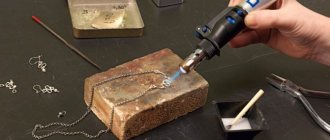
The induction soldering iron is currently the pinnacle of technical achievements in the field of metal soldering with eutectic solders. In essence, an induction-heated soldering iron is a miniature induction furnace: the HF EMF of the inductor coil is absorbed by the metal of the tip, which is heated by Foucault eddy currents. Making an induction soldering iron with your own hands is not so difficult if you have a source of HF currents at your disposal, for example. computer switching power supply, see e.g. plot
Video: induction soldering iron
However, the quality and economic indicators of induction soldering irons for conventional soldering work are low, which cannot be said about their harmful effects on health. In fact, their only advantage is that the tip stuck to the holder in the body can be torn out without fear of tearing the heater.
Induction mini-soldering irons of the METCAL system are of much greater interest. Their introduction in electronics production made it possible to reduce the percentage of defects due to installer errors by 10,000 times (!) and lengthen the work shift to a normal one, and the workers left after it cheerful and capable in all other respects.
The structure of a METCAL type soldering iron is shown at the top left in Fig. The highlight is the ferronickel coating of the tip. The soldering iron is powered by RF at a precisely maintained frequency of 470 kHz. The thickness of the coating was chosen such that at a given frequency, due to the surface effect (skin effect), Foucault currents were concentrated only in the coating, which gets very hot and transfers heat to the tip. The tip itself turns out to be shielded from EMF and induced potentials do not arise on it.
Design of induction soldering irons for microcircuits
When the coating warms up to the Curie point, above which the ferromagnetic properties of the coating disappear in temperature, it absorbs EMF energy much weaker, but still does not allow RF into the copper, because maintains electrical conductivity. Having cooled below the Curie point on its own or due to heat transfer to the soldering, the coating again begins to intensively absorb EMF and heats up the tip. Thus, the tip maintains a temperature equal to the Curie point of the coating with an accuracy of literally one degree. The thermal hysteresis of the tip is negligible, because determined by the thermal inertia of the thin coating.
To avoid harmful effects on people, soldering irons are produced with non-replaceable tips, tightly fixed in a cartridge of a coaxial design, through which they are supplied to the RF coil. The cartridge is inserted into the soldering iron handle - a holder with a coaxial connector. Cartridges are available in 500, 600 and 700 types, which correspond to the Curie point of the coating in degrees Fahrenheit (260, 315 and 370 degrees Celsius). Main working cartridge – 600; The 500th is used to solder especially small smds, and the 700th is used to solder large smds and scatterings.
Note: to convert Fahrenheit to Celsius, you need to subtract 32 from Fahrenheit, multiply the remainder by 5 and divide by 9. If you need to do the opposite, add 32 to Celsius, multiply the result by 9 and divide by 5.
Everything is great about METCAL soldering irons, except the price of the cartridge: for “(company name) new, good” – from $40. “Alternative” ones are one and a half times cheaper, but are produced twice as fast. It is impossible to make a METCAL tip yourself: the coating is applied by spraying in a vacuum; Galvanic at the Curie temperature instantly peels off. A thin-walled tube mounted on copper will not provide absolute thermal contact, without which METCAL simply turns into a bad soldering iron. Nevertheless, making an almost complete analogue of the METCAL soldering iron yourself, with a replaceable tip, although difficult, is possible.
Induction for smd
The design of a homemade induction soldering iron for microcircuits and SMD, similar in performance to METCAL, is shown on the right in Fig. Once upon a time, similar soldering irons were used in special production, but METCAL completely replaced them due to better manufacturability and greater profitability. However, you can make such a soldering iron for yourself.
Its secret is in the ratio of the shoulders of the outer part of the tip and the shank protruding from the coil into the inside. If it is as shown in Fig. (approximately), and the shank is covered with thermal insulation, then the thermal focus of the tip will not go beyond the winding. The shank will, of course, be hotter than the tip of the tip, but their temperatures will change synchronously (theoretically, thermohysteresis is zero). Once you have set up the automation using an additional thermocouple that measures the temperature of the tip tip, you can then solder in peace.
The role of the Curie point is played by a timer. It is reset to zero by a signal from the thermostat for heating, for example, by opening the key that shunts the storage tank. The timer is started by a signal indicating the actual start of the inverter operation: the voltage from the additional winding of the transformer of 1-2 turns is rectified and unlocks the timer. If you do not solder with a soldering iron for a long time, the timer will turn off the inverter after 7 seconds until the tip cools down and the thermostat issues a new heating signal. The point here is that the thermal hysteresis of the tip is proportional to the ratio of the times of switched-off and switched-on heating of the tip O/I, and the average power on the tip is proportional to the reverse I/O. Such a system does not maintain the temperature of the tip up to a degree, but it provides +/–25 Celsius with a working tip of 330.
Equipment
The radio materials tool contains some accessories, the direction and characteristics of which may vary. It is necessary to familiarize yourself with the complete set in order to avoid downtime and poor-quality connections. The average soldering iron with a temperature controller has:
- A set of soldering tips usually consists of 5 items to perform various actions.
- Thermal sensor for own adjustment of the tool.
- Heating indicator, a regular LED that signals when the set temperature has been reached.
When purchasing, you should pay attention to the length of the wire; the length should be at least 1.5 meters; in this case, you probably do not need to use extension cords. The heating component can be of two types:
- ceramic;
- made of nichrome wire.
Temperature-controlled soldering iron included
The heating device must have a change of tips to perform different processes. Cheap products do not provide such a modification, so you need to choose a tip according to the type of action.
Self-production of power regulators for soldering irons
You can not only purchase a power regulator for a soldering iron, but also quite easily assemble it yourself. It is mounted into a break in the network cable of devices in housings from small old electrical appliances. For soldering circuits, perforated textolite boards with copper coating are used.
Below are diagrams of the most commonly assembled thermostats based on radio components such as a variable resistor, triac, and thyristor.
From a resistor
The simplest thermostat for a soldering iron based on a variable resistor is assembled according to the diagram below.
Temperature regulator circuit using a resistor with variable resistance
From a thyristor
The thyristor-based thermostat board has the following circuit diagram.
Thyristor-based temperature controller circuit
From a triac
The simplest thermostat using semiconductor parts such as triacs can be assembled according to the following scheme.
Triac thermostat circuit
Types of regulators
Devices for connecting various types of radio components have several types of characteristics. Soldering stations with heat and load adjustments are produced by the manufacturer with different parameter settings. Main varieties:
- Changing the voltage and power of the node is possible using a triac. This modification is most common when using heating components in radio engineering.
- Thyristor type adjusting element.
- Modification to increase the performance of the device allows you to change the output force to the required values.
- The indication makes it possible to recognize in which mode the heating is being carried out.
- Low-voltage controllers are used in designs designed to operate with a voltage of no more than 36 Volts.
You can probably make components that have adjustable temperature volumes with your own hands. A simple structure without interference is used, which makes it possible to extend the service life of the heating element. The galvanic component is considered reliable; its versatility allows the design to be used with various modifications and models.
Manufacturing the body and installing the heater
The body is made of tin from a tin can. The workpiece is a rectangle, the width of which depends on the diameter of the heater. In my case, the dimensions of the workpiece were 20.5 X 80 mm. Rows of holes are made to reduce heat transfer
along the body into the handle.
The workpiece is rolled into a tube on a mandrel of suitable diameter. A heater is inserted into the resulting tube.
The heater is fixed
in the housing by tightly wrapping the housing in the heater area with steel wire. In order for the ends of the wire to meet, I first bent it at a right angle, stepping back a few centimeters from the beginning, and laid this section of wire in the gap between the edges of the body plate bent into a tube in the direction from the future handle to the tip. Then he tightly wound the wire turn to turn in the direction from the tip to the handle and connected the ends by twisting. The twist was tucked into the slot of the case.
Low frequency devices
A design feature of the device is the repair of thin connections that can be burned through in the usual way. Stabilizers for 12 and 36 V are used, depending on the output power. There are options with a microcontroller, which is installed in products when operating with sensitive parts.
It is important to understand that the operation of such devices will be less productive.
The performance is not enough to quickly heat up the tip; the maximum degree of heating does not reach larger mechanisms.
Copper fixtures
The structure is made of copper wire twisted in a spiral pattern. Copper is capable of carrying the low current produced by small transformers. The adjustable heating components are equipped with a temperature sensor, which is responsible for controlling the tip. The thermocouple is installed on the working tip, which allows you to adjust the temperature level to the required state. The copper spiral does not pass electric current through itself, the performance of the unit stops, or the load indicator changes. Types of copper heaters:
- with wire wound around the body, preventing voltage from reaching the tip;
- The insulated structure avoids heat loss when using the device.
Homemade thermostat
The quality of copper depends on performance; adding additives in order to save money by the manufacturer can significantly reduce the service life and damage the parts being repaired.
Main details
The soldering device is made from a copper rod. A nichrome spiral heats the device. It is important that the heat is immediately transferred from the heating element to the tip - this is the name given to the rod with a wedge-shaped tip. It is inserted into a steel tube, which is wrapped in glassy fabric or mica.
A wire is wound around the mica, which serves as a heating element. To reduce heat loss, nichrome wire is wrapped with asbestos. The ends of the nichrome spiral are connected to the conductors of the electrical cord. To ensure reliability and preservation of the generated heat, the spirals are bent and folded in half at the point of connection with the copper wire. Additionally, they are compressed at the coupling point.
The listed elements are located in a metal case. It can be made in two ways: welded from two parts or constructed from two pieces of metal.
Overlay rings are used to secure the housing to a metal tube . After applying electric current, it is distributed from the nichrome onto the spiral, and after that the heat flows to the tip.
For soldering low-power diodes, experts recommend using an electric current of up to 12 W. Large parts and thick connecting wires need to be soldered with more powerful devices. A soldering iron with a power of 40 to 60 W is suitable. Parts that are complex in design and heat transfer are soldered with devices with a power of 100 W or more.
Ceramic heaters
Unlike products equipped with nichrome wire, the ceramic component can last longer than its competitor. The ceramic element allows operation at the maximum permissible thresholds, the resistance is minimal. Electrical voltage spreads along the tip, resulting in heating. Ceramic heaters require attention; under mechanical stress they are destroyed and become unusable.
Soldering iron with ceramic heater
The price of a soldering iron with a ceramic tip is higher, so it is important to choose high-quality material. Durable and reliable operation is achieved through careful use of the component.
Modification of the soldering iron itself is not difficult at all
Its essence is simple - remove the triac and connect the soldering iron wire to the heater directly. Personally, I replaced the wire (the wire with the plug will come in handy), and hung the triac by one leg on the soldering iron board. The original regulator is no longer used. I use the twister as a plug and retainer for the board.
I haven't had much practice with this soldering iron yet, but I see no reason for a negative result. The first one I converted works great and is my main one. What should you do if you decide to redo yours? Measure the resistance of the heater when cold and after warming up. Naturally in a state disconnected from the network.
- If they approximately coincide with mine, you can safely repeat them with my denominations.
- If not, then you will have to select the values for R1, R2, R3.
I haven’t experimented with soldering irons with nichrome heaters, so I can’t give any recommendations.
Advantages and disadvantages
When choosing a device for soldering radio components, you should pay attention to the technical documentation. You should not ignore the advice of a professional, because... Years of experience can help beginners choose the right device. The choice between a ceramic and a conventional device can lead to a dead end; an inexperienced craftsman should familiarize himself with the negative and positive sides of each product. Advantages of copper tips used with soldering iron temperature control equipment:
- the affordable price makes it possible for a novice master to purchase it;
- resistance to mechanical stress allows you to avoid breakdowns of the mechanism when the process has not yet been fully mastered.
Negative sides:
- Copper wire is not known for its durability due to exposure to high heat levels over a long period of time. It is possible to avoid overheating by pausing during the process; the method under consideration keeps even cheap models intact.
- Slow heating of the electrical connection.
Ceramic soldering irons, including a thermostat, have the following advantages:
- the integral system makes it possible to avoid device failure;
- the configured temperature readings are available immediately after connecting to the network, some models heat up in less than a minute;
- reliable unit subject to operating rules.
When using any device you are faced with a number of negative aspects, ceramic products are no exception. A destroyed tip is replaced only with the original one, due to the design features of each model. If dropped, the heating component cracks and loses its working properties.
Expert advice
To successfully repair the email. soldering iron with your own hands, you need to do it as experts advise:
- When rewinding a spiral, you must carefully ensure that adjacent turns are located at a distance from one another. A mica spacer must be placed between the winding rows.
- When soldering deformed or faulty parts, mechanical stress on the cord must be avoided. This will preserve the electric heater for a long time.
- Do not leave the soldering iron coil on for a long time to avoid short circuiting of the electrical wiring if the parts included in it malfunction.
- During repairs, you need to use the power regulator to select a safe heating mode for the tip.
- If it was not possible to avoid overheating of the device and use the tip safely, then carefully isolate the melted area. This is done with electrical tape and cambric placed over the damaged tip.
It’s easy to repair a soldering iron with your own hands. To do this, you need to understand the causes of the malfunction and correctly calculate the power of the electrical network for operation.
Source
Why increase power?
It is not advisable to purchase several options for performing soldering work of various types. Increased intensity is used for short-term exposure to elements; fragile parts may not withstand high temperatures and become unusable. Burnt tracks located near the controllers can affect the operation of the part being repaired.
Soldering station with thermostat
Less power output contributes to slow heating and low temperatures. With the presented indicators, during the soldering process it is necessary to act on the material longer before melting begins. Long-term heating can also have a detrimental effect on the board. To avoid serious consequences, you should correctly select the level of return through regulation. For example, to adhere massive objects, it is necessary to increase the intensity until the time of exposure to the elements is less than the melting point and provided that the appropriate solder is used.
Rules for using power tools
On the shelves of construction stores you can find different models of electric soldering irons that operate on mains power - from 12 to 220 W. The process of choosing a tool should take into account the safety of the working craftsmen and the voltage in the electrical network at the work site.
If the instrument is made independently, then a thin wire will be required for its correct reconstruction. It will be wound onto a spiral. The required power is from 12 to 100 W, even more is possible. The material will spread evenly over the surface of the plates if the melting temperature exceeds the temperature in the soldering iron itself.
Switches and Dimmers
A simple type switch allows you to select a position in two directions. The unit is operated at minimum and maximum output values, allowing only to save energy. At the minimum level, the tip is maintained by the required degree of heating on the stand; pressing the switch warms it up. With a product equipped with the specified type of switch, it is difficult to perform high-quality fusion of metals, because There is no full parameter setting. Dimmable varieties of adjustable devices allow you to select important parameters.
Homemade dimmer for soldering iron
The device includes a dimmer, which is present in the grid between the power cable and the heating element. The adjustment is made by monitoring the voltage; these mechanisms are popular among beginning radio amateurs due to their low price.
How does a soldering iron work?
Normal operation of a soldering iron is possible if two basic conditions are met: it must melt the solder and maintain the most suitable temperature. It is necessary to take into account the wide range of melting temperature 150-320C, as well as the degree of heat resistance of the elements being connected. With prolonged heating, many parts become inoperative, their insulation properties are reduced or completely lost. Connecting elements with a large area and mass increases the dissipation area of the contacts, so in such cases a power and temperature reserve is required.
Conventional unregulated electric soldering irons are not capable of meeting the conditions required for normal soldering. In this regard, increasing or decreasing the temperature is carried out using a special regulator connected directly to the device. It is based on resistors, due to which changes in temperature, voltage and power occur.
There are recommendations for choosing the most optimal operating temperature:
- During normal soldering, without using parts sensitive to overheating, the tip of the device should, on average, heat up 10C above the melting point of the solder, when all of it becomes liquid, and not just some part.
- In the case of connecting large contacts, it is not the heating that should be increased, but the power of the soldering iron itself. A device with low power, although it maintains a high temperature, will still not be able to overcome dissipation. Compensation for massive parts is carried out due to the appropriate sizes of the tip, heated by high power.
- Before soldering, you need to carefully study the technical data sheet for each radio component, which displays the maximum permissible heating temperature of the housing. It is recommended to change the temperature at which soldering is performed by adjusting the power, rather than simply increasing the degrees. This will reduce the contact of the part with the sting to a minimum. That is, in a short period the solder melts, and the temperature of the case only rises slightly.
Control units
More advanced systems have a control unit consisting of a set of regulators and microcircuits. The compactness allows you to place the drawing in the handle of the soldering iron, which is very convenient in the process. The control sensor is located outside the housing, which makes it possible to select an indicator without interrupting the soldering process.
There are soldering irons that have an external power supply. This device makes it possible to work with a stable voltage on a rectified current.
The unit adjusts the parameters of the potential differences in the electrical network, regardless of the modes; with some actions this condition must be observed. The varieties of control units can be confusing; if mobility is important, it is better to pay attention to the internal arrangement. External blocks allow for better contact; a type of soldering station that includes a hair dryer is provided.
DIY temperature regulator
Making a soldering iron with do-it-yourself adjustment requires knowledge of electrical engineering. If you have experience, it is proposed to make the mechanism from a conventional heating element with a power of 60 watts. High-quality connections can only be made when using a heating value balancer. Assembly is carried out by implementing some modifications and involves the use of available materials. The simplest system includes:
- thyristor model KU101G;
- resistor SP – 1;
- diode operating at a current of at least 1A.
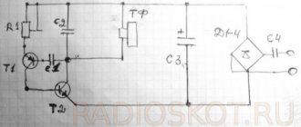
Thermostat circuit for a low-voltage soldering iron
Installation of the model is possible without the use of a board, in a power supply housing of any size. The connection is placed on the resistor body, to which the connector for adjusting the degree of heating is adjacent. The result is an adjustable device with an output power of up to 60 watts. Schematic drawings for more powerful devices include slightly different components. Assembly is carried out on a circuit board; variable resistor R2 is responsible for adjustment, which operates in the range from 50 to 100%. The maximum permissible load is 300 watts, sufficient for a household device. Circuit options depending on the power limiter The power of the device can be adjusted in several ways; the differences lie in the use of a semiconductor controller that performs the necessary tasks. Schemes can be built using several components, depending on the purpose:
- The thyristor works like an electronic switch; the current starts in one direction. The structure is made with three outputs, a cathode, an anode, and a control electrode. Applying a pulse to the electrode causes the thyristor to open; closing occurs after stopping the supply or changing the direction of the current.
- Semiconductors that conduct current in both directions are called triacs. The housing has a control gate and power electrodes; the operation is essentially similar to two connected thyristors.
- The design of control sensors uses parts known to radio amateurs, such as a resistor, diode, capacitor, and microcontroller.
In most cases, a thyristor or triac is used, the precise debugging is regulated using a microcontroller added to the circuit.
Five ways to adjust the temperature of a soldering iron
To perform various electrical work and assemble electronic circuits, a tool such as an electric soldering iron is often used. Its simplest type, which can be purchased at any hardware store, usually has a basic design.
It includes a heating element, a tip, a handle, usually wooden, and a power cable or cord. In some versions, the soldering iron can be equipped with several replaceable tips.
The power of such a soldering iron is fixed, most often 40 or 60 watts. But it is more convenient to use a tool with the ability to adjust power. Such models are also produced, although they are more expensive.
Recommendations for testing and adjustment
When the adjustment knob is rotated, the voltage changes; the test is performed under load, i.e. with the soldering iron turned on. Accurate readings can be obtained using a multimeter. Also, the load level is determined by the connected incandescent light bulb; when the parameters are changed, the light intensity changes. A do-it-yourself voltage regulator helps with soldering work, regardless of the type of material. Varieties of circuits allow you to select exactly the modification that allows you to make a high-quality connection.