I present to your attention a doorbell circuit that was assembled many years ago and has been in use for the same amount of time. It would be more correct to call this device: “Waste into income!” Because what it was made from was literally lying underfoot. This was during Soviet times. I was working at a small automatic telephone exchange at the time and had a lot of free time that I wanted to convert into money. Then he began to collect electronic calls based on this scheme and insert them into rotary telephones. The installer of the city automatic telephone exchange willingly helped me with the implementation, making his own profit from it. The device imitates the sound of a bouncing ball. All characteristics are adjusted by selecting the capacitance of the capacitors and adjusting the variable resistor.
Electrical circuit diagram
Once assembled without errors, it starts working immediately. Power supply is possible from a 12 volt DC source (then diodes D1-D4 and capacitor C4 are excluded). The ringing pulses of an alternating current telephone exchange are 110 volts 25 hertz - in this case, the capacitance of capacitor C4 should be 1 microfarad per 400 volts.
AC voltage 220 volts 50 hertz, when used as an apartment bell (in this case, the capacitance of capacitor C4 should be 0.5 microfarads at 400 volts). The device was assembled using pieces of foil getinax, which were cut on a machine (Skillful hands) with a small circular cutter. I used one board as a conductor for drilling holes, but it can also be assembled using wall-mounted installation.
How to make an electronic doorbell with a triple tone sound signal - diagram
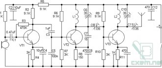
Scheme of an electronic doorbell with a triple tone sound signal:
Triple ringer
The diagram shows:
- S1, S2, S3 - buttons A1 0.4-127;
- D1 - zener diode D814V;
- D2 - zener diode D816A;
- D3 - zener diode KS468A;
- D4 - diode D226G;
- R1 - resistor MLT-0.5, 5.1 kOhm;
- R2, R4, R7 - resistors MLT-0.5, 4.7 kOhm;
- R3 - resistor MLT-0.5, 2.4 kOhm;
- R5, R6 - resistors MLT-0.5, 120 kOhm;
- R8 - resistor MLT-0.5, 820 Ohm;
- R9 - resistor MLT-0.5, 560 Ohm;
- C1, C2 - capacitors K73-17, 4.7 µF, 63 V;
- VT1, VT2 — transistors KT630G;
- VT3, VT4 - GT402I transistors.
Parts used
Transistor T1 - mp25-26, T2 - kt605 or p307-309, but p605 works better, diodes D1-D4 - D226, but others are possible, although D226 gave better results. Capacitors C1-0.1 C2-0.05, trimming resistor - 47k, C3 - 100 microfarads per 100 volts. The telephone capsule was used as an emitter, but only very old ones (large diameter).
The use of a Czech capsule with a resistance of 50 ohms gave very good results, but it has one feature - to achieve good volume, you need to remove the plastic plug from the side of the contact screws, under which there is an adjustment screw and, having turned on the device, use a small screwdriver to make adjustments, unscrewing and tightening screw to achieve maximum sound volume.
Warning! If you are going to use this device as a doorbell, do not set it up by connecting it to a 220 volt network! You may be exposed to high voltage! Set it up by connecting 12 volts to DC, and then connect the mains voltage.
After the doorbell gave up its life, I dug up an old telephone on the mezzanine, tore out this electronic bell from it, packed it in a box of cotton swabs, and now it continued its service above the door. The author of the project is Wolf9405 .
Discuss the article DOORBELL FOR BEGINNERS
A high-quality wireless bell for the front door of an apartment or house is in no way inferior to its wired counterpart, and even surpasses it in ease of installation and dismantling. The signal transmission unit can be so miniature that outwardly wireless call models are no different from regular ones. They are equipped with a video peephole combined with a motion sensor, backlight, anti-vandal cover and other little things to increase the comfort of use.
Installation of the sound mechanism
If all the wires in the apartment are already laid, then installing a doorbell will not take much time. The device operates on current, so you must follow safety rules when working with electrical devices. The electrical product is connected only after the power has been turned off in the entire apartment.
The doorbell is connected to the current by connecting its contacts to the apartment wiring. If they are too long, they need to be trimmed and cleaned with a construction knife. Electricians recommend lightly squeezing the already connected wires with pliers so that the connection is more reliable and the contact is better. We isolate the connections and check that everything works. If a four-wire mechanism is connected to two-wire wiring, then the phase and zero that will participate in the connection are determined. The remaining wires are connected to each other and carefully insulated.
If the wired bell works successfully, then it’s time to start attaching it to the wall.
The installation location is usually in the corridor or hallway. At the same time, there should be no radiators or other heating devices within a radius of one and a half meters from the device. At the installation site in the wall, a hole is made with a drill and the sound mechanism panel is attached using dowels and screws. Hidden mounting holes are provided by all device manufacturers. A hole is drilled in the door frame to connect the wires between the sound panel and the button.
Key Features of Wireless Calling Models
When choosing any item, first of all it is worth assessing how suitable it will be for the conditions in which it will be used. To accurately understand whether it is worth installing a wireless call at home, you need to evaluate their features in more detail:
- There is no need to run wires from the button to the speaker. This is the main difference, often influencing the choice of this type of device for a private home, in which the front door is quite far from the gate and a friendly dog runs between them.
Here you can install a regular wired bell without any problems, but it is best to bury the wire underground. Otherwise, it may stand out somewhat in the yard design.
- Autonomous power supply. Since wireless calls are battery-powered, when the lights go out, guests will not have to call the host from the street for a long time. This is also a determining factor for summer cottages that do not have electricity. Powered by batteries at the same time creates certain inconveniences associated with their periodic replacement, but here you have to choose what is more important.
- A wireless call cannot be installed everywhere. It is necessary to look at the distance from the receiver to the transmitter and the presence of obstacles between them that impede the passage of the radio signal.
- If the house has more than one door (or gate), but several, then you can purchase an electric bell with two buttons. This will significantly reduce the cost of their installation compared to wired models.
- Easy installation, dismantling and transfer of the button. This feature is rarely in demand, but if you need to move the gate, change the side it opens, or install a mailbox exactly where the button is located, then it will be much easier to do this. If with a standard call you inevitably have to re-wire the wiring, then the wireless one is simply re-wired.
This may also be one of the disadvantages - some manufacturers make bell buttons with Velcro, which, if done poorly, can quickly fall off. If you are buying just such a bell, then you need to evaluate whether it is worth additionally screwing it on.
Replacing the device
Sometimes it becomes necessary to replace certain parts of equipment. In the event that work is carried out with a wireless type of device, then often there are simply no difficulties. You just need to remove the unusable button and install a new one in its place.
A small number of components and the absence of wires make it easy to identify a failed device
There are practically no difficulties in connection with the repair of wired calls. Especially if the replacement is made with a similar model. Thus, you need to dismantle the button and the main bell unit, disconnect them from each other and, of course, disconnect them from the power supply. Then connect the new device as described above.
Repairs on such models involve replacing batteries.
There are times when a breakdown occurs due to damage to the wire. In order to restore the operation of the device, it is necessary to remove the worn wiring and place a new one in its place. If at this moment the mechanical bell is going to be changed to an electronic model, then some problems may occur during the installation process.
The absence of a signal from a wired device means ringing of the supply wires
The fact is that for the first type, power is supplied from the network, but the second type is powered from built-in or external devices. And therefore, to change such equipment it will be necessary to carry out additional construction work. But you can go another way:
- First, you need to remove the originally installed bell, and in its place install a new device, which should include a transformer and a voltage rectifier.
- A new electronic bell is connected to the rectifier contacts. In this case, the installed transformer must provide a voltage of 10–12 V. This additional device must be placed in a special box and the necessary circuits must be connected using pre-insulated wires.
During periodic maintenance, it is useful to check the integrity of the wire contacts
How to install an electric lock on a gate, see the link.
Scheme and principle of operation of wireless calls
For the average user, the principle of operation of wireless calls is very simple - the transmitter button is pressed, the radio signal from it goes to the receiver, where it activates an electrical circuit that supplies voltage to the speakers and a melody plays.
Despite the fact that the device diagram is rarely attached to it by the manufacturer, numerous radio amateurs have adopted the remote method of controlling the device itself, making not only bells with their own hands, but also various control devices - a wireless light switch or a remote garage door lifter.
The circuits of these devices are easy to manufacture and unpretentious in operation. The first two are separate boards for the button and the receiver, and the third circuit does not even require any configuration - the receiver is a regular supergenerator and, according to user reviews, everything is highly stable.
DIY mechanical door lock
A popular device among amateur mechanical doorbells is a device where the sound comes from a small bell when a suspended tongue strikes its dome. In addition to this, to make it yourself you will need:
- long metal chain (can be soldered from several sections);
- wooden plank;
- steel perforated tape, for example, 0.5×12×800 mm in size;
- insulating tape;
- fasteners (screws, nail);
- paint for painting boards;
- soldering iron;
- set of locksmith tools.
A mechanical bell is made in the following order.
- The board is painted in a color that matches the interior design of the apartment.
- A spring is made from punched paper tape, both surfaces of which are covered with electrical tape;
- The spring is made in the form of a twisted spiral.
- One end of the spring is made in the form of a suspension for a bell, and the other is a rolled surface for basing the fastening axis, which is a nail.
- An eyelet is installed on the board through which the chain is passed.
- To add design elements to the bell, a specially engraved plate is attached, and a decorated plug is inserted in the center.
- One of the ends of the chain is attached to the spring, and the board with the bell itself is installed using self-tapping screws on the wall.
Video eye for wireless calling
The general scheme of installing a bell on a door can allow you to remotely monitor an entrance or street. If a video peephole with a camera is installed on the front door or gate, then inside the house you can immediately see who is calling. Depending on the device model, the image transmitted by the video eye is displayed on a separate receiving display or transmitted to an ordinary computer monitor. The quality of the picture is determined by the camera installed in the video peephole.
Read also: How to cut protective glass for a smartphone
When choosing such a device scheme, it must be taken into account that the video eye with the camera requires a more thorough power supply. The main solutions to this problem are as follows:
- Choosing a high-quality kit with minimal power consumption (if you need to record constantly).
- The scheme provides for using the camera only after pressing the call button (the video eye records only those who called).
- The video peephole and camera are powered separately from the network. It would seem, why would there be a wireless call, but this scheme also occurs quite often.
- The connection diagram should be equipped with a motion sensor (the video peephole and camera start working when someone passes by - useful if there are people with an inadequate sense of humor in the entrance).
Depending on why you plan to install a video peephole with a camera, the resolution of the latter is selected - what quality it will take a picture. It should also be taken into account that the higher the resolution, the more data will be transmitted by the camera via a radio channel per unit of time and the more demanding such a circuit is in terms of power supply.
Checking operation and reasons why the doorbell in an apartment may not work
It is difficult to make a mistake when connecting an electric doorbell, but it happens. It also happens that if the connection is made correctly, the bell does not work (this may be due to a defective product or lack of power). To check the functionality of the device and identify the reasons why the call may not work, it is necessary to perform diagnostics consisting of the following steps:
- Turn on the power and check if the bell works.
- With the power turned on, use a tester to check the presence of voltage on the main unit and on the bell button.
- When the power is turned off, use a tester or multimeter to test each conductor and determine the integrity of the circuit.
- If everything is in order with the conductors, check for good contact in the bell button.
- If, after testing the conductors and checking the electrical connection diagram, the fault persists, then there is a manufacturing defect: return the bell to the store and purchase a new device.
In the case of a wireless device, the cause of the malfunction may be incorrect installation of the batteries, as well as non-compliance with the instructions for the communication range of the main unit and button. Check that the positives and negatives of the battery and the socket match, and also check the installation range.
What to look for when choosing a wireless doorbell
What is a lithium ion battery - device and types
Lighting control schemes using different types of switches
How to connect a two-key switch yourself
How to connect a wire to a single-key switch?
How to properly connect an electric oven and hob: choosing a cable, socket with plug, machine and connection diagram
Why do you need a magnetic starter and how to connect it
Nuances when choosing a wireless call
Like conventional models, wireless doorbells for the front door must be selected based on certain rules, especially if this is the first time purchasing such an item and there is no experience in operating such devices.
Distance
The main quality for a wireless call is the range and strength of the signal that is transmitted from the button to the speaker. If there are 5-10 meters between them, then this indicator is hardly worth paying close attention to, and when you plan to use the device at a distance of 50-150 meters, then it is better to test it before purchasing and agree with the seller about an exchange or return, if necessary This electric bell won't work anyway. This is also quite possible - after all, you cannot see with your eyes whether there are obstacles in the path of the signal or not.
Nutrition
The number of batteries required to operate the device, what types are used, and how often they will have to be changed. It’s unlikely that anyone will answer the last question truthfully, but if the seller really praises the unprecedented efficiency, then it’s worth thinking about. You should not pay special attention to the type of batteries - the main thing is that they can be freely purchased.
Equipment
Everything is simple here - you need to check your passport so that everything is in place. You need to pay special attention to a call equipped with a video eye, several buttons and other additional little things. If at home you discover that some part is missing, then at best you will have to go back, and at worst you will have to prove that this is a factory shortage and not the loss of spare parts due to the fault of the buyer.
Overpayment
Opportunity to purchase a simpler model. If you just need a call to ring, then purchasing a device that can be connected to a computer in order to record your ringtone into it and pay twice or three times for it - most likely there is no point.
Fastening
Velcro can leave traces of glue on the surface if the button is moved, and the screw has to be screwed into the wall or front door. The Velcro may fall off, but the screw can be screwed in only once. Which is better - you need to choose according to the situation.
Manufacturer's warranty
There is nothing particularly broken in simple calls and taking it for repairs may cost more than buying a new device, but it is advisable to clarify this issue. If you purchase a model with a camera, an internal screen and a motion sensor, then you should not only pay attention to the warranty, but also urgently require that all documents be filled out.
Electronics can last 10 years, or they can fail after a couple of months, especially if they are used occasionally.
General impression
In addition to the fact that the device must be beautiful, you need to look at the quality of the materials from which it is made. If you are purchasing a street bell, it is better to choose a button with a vandal-proof housing. Next, pay attention to the melody that you will have to listen to every day, and choose a device from the manufacturer. The last point is quite important - many characteristics of the device and the quality of its warranty service depend on it.
You can see how a wireless street bell works in the following video:
Choosing an electric bell
Instructions for choosing a device suggest:
- Contact a specialty store where experienced consultants provide extensive information on many types of doorbells.
- Determine the type of electric bell for your home. It is worth considering its cost, appearance, connection method, the ability to adjust the volume and the ease of installing the device yourself.
- Determine the ringtone.
- Gong bells that make trumpet sounds are distinguished by their excellent design and beautiful appearance.
- A useful feature for a bell is its illumination in the dark. For this, small LEDs or luminous materials are used.
Read also: What is the temperature of a hair dryer?
An excellent solution for installing a bell in a private home or country house is to purchase a wireless electric bell. One part of it is attached to the gate, and the second in the house. Using a wired call will be inconvenient due to installation difficulties and the high cost of laying the cable.
Setting up a call
Based on the size of the button and the functionality of the device itself, the location for their installation is selected. There is not a lot of choice here - the button needs to be clearly visible, and if this is an entrance, then it needs to be clear which door it belongs to.
- The wall near the door. This mounting location is used most often - if the button is Velcro, then its fastening depends on whether the wall is painted or whitewashed. In the first case, the surface must be thoroughly degreased, and in the second, it is better to use a screw.
- Door casing or door leaf. Everything is extremely simple - the usual fastening with a self-tapping screw.
- Through the gate of a private house. Here you need to think more not about where and how to screw the button, but how to protect it from direct rays of the sun, rain and other atmospheric phenomena.
Also, in a private house, it is worth considering a bell with two speakers in order to duplicate the bell signal in the workshop, garden and other places where the owners can be often and for a long time.
When installing speakers inside the house, there are two options - if it’s just a bell, then install it as inconspicuously as possible, but taking into account that you may have to turn off or change the melody, which requires relatively free access to it. If you are using a surveillance monitor and an intercom, then you need to make a separate stand for them or use a niche in the wall for this (if there is one).
Types of residential calls
There are two types of electric residential bells based on the connection method - wired and wireless. Wired ones are connected to a 220 V network, there are models that operate on a reduced voltage of 12 V. They are called wired because the bell button and the indoor unit must be connected by wires.
Wired calls - the button and the internal unit must be connected by wires
In wireless electric calls, the button and the internal unit are not physically connected. They contain a miniature transmitter (in the button) and a receiver (in the indoor unit). They communicate with each other at some frequency. There are two types of wireless call power:
- The indoor unit and button are battery operated.
- The button is powered by batteries, the internal unit is powered by a 220 V network. Moreover, there are two ways to implement internal units: with a standard connection to the terminals by wires and with installation in a socket. In the latter version, there is a regular electrical plug on the body. In this case, connecting a bell in an apartment or house is very simple: you need to install the indoor unit into a socket, screw the button on the entrance/gate and insert the battery.
Wireless calls by connecting the indoor unit via a socket
As already mentioned, in the wireless version, the button and the electric bell “communicate” with each other through signals. Signals can be transmitted in analog or digital form. More reliable signal transmission in digital format - less susceptible to distortion. In addition, such models have the ability to change the channel through which reception/transmission occurs. This is not possible when transmitting an analog signal. Why is this bad? Call range is 100 m or more. And if there is some device in this area that operates on the same frequency (bell or other), your receiver can pick up its signals. In this case, false positives occur.
There are also doorbells that separate apartment and street doorbells. They differ in that for those installed outdoors, the buttons are sealed and dustproof. In addition, it is recommended to install them under a small canopy - there will be fewer problems.
This is interesting: Cable under a concrete path: let's look at it in detail
Radio call and remote control of devices
Not so long ago, this miracle of Chinese industry entered our lives, but immediately won our hearts with its simplicity and cheapness. And its simplicity lies in the following: I bought a bell, turned it on, threw it on the closet, and glued the button to the door. That's it, no wires for you, drilling holes for fastenings, etc. . . .
But still, let's look into it and look at the circuit diagram.
Button. Three transistors, 12 volt battery. The high-frequency generator is assembled according to a capacitive three-point circuit, an amplifier-converter. Converts from a frequency of about 433 MHz. What surprised me was the parallel connection of two circuits, one is tuned to the primary frequency of the generator, and the second catches somewhere around the 10th harmonic and is excited at a frequency of 433 MHz. Our Chinese friends again found an original, and most importantly simple solution to the problem using a minimum of details.
Read also: How a cyclone filter works
The most interesting thing is that the transmitter does not have a transmitting antenna, of course it is inside, i.e. the outline itself is her. Thanks to the use of ultra-shortwave range, this is quite enough.
Call. The receiver is assembled on a single transistor according to a regenerative detector circuit. The signal received from it goes to the operational amplifier. Next, the signal enters the SOUND CHIP. It is not difficult to guess that he is the shaper of the melodies that we hear. From it to a power amplifier, assembled on one transistor, and into a dynamic head. That's it, I just want to note the relatively small current consumption in standby mode.
They took it apart, looked at it, sorted out the work. All? No, not all! The bell is an almost universal transmitter-receiver circuit. Based on it, you can assemble many other interesting devices.
As an example. The bell controls the light.
We take our call and connect the circuit shown below.
This is a common trigger. When it receives an impulse from a bell, it switches to one of the fixed positions. The output of the trigger is a relay, and a controlled device is connected to the relay, in our case it is an incandescent lamp.
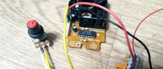
An example of the location of the bell and button.
Location of parts on the printed circuit board.
PS: I was tormented by the question: where can I get power for this circuit? Shouldn't we run a separate line? Here's where you can find a way out - it's in double wiring. If your wiring in the ceiling is designed for two lamps, and the switch has two buttons, the answer came by itself - one button controls the device, and the second is powered by, say, charging from a mobile phone (it is economical).
How to connect the bell to power
This chapter will focus on electrical connections. We will consider wired and wireless models separately, since the power supply and methods of connecting/supplying it are different.
Wired models
The vast majority of wired doorbells are powered by 220 V and only about 10-15% by 12 or 24 V. When installed outdoors, in the courtyard of a private house, the second option is safer, since the reduced voltage does not pose a danger to humans. But in this case, it is necessary to have an inverter that converts 220 V into a safer low-voltage power supply of 24 or 12 V.
When connecting the bell to a 220 V network, power can be taken from the nearest junction box. The doorbell indoor unit is usually installed next to the door. There is usually a distribution box from which power goes to the lighting. This is where you can connect the call.
The doorbell connection diagram is simple: the phase is turned on to the button, from which it goes to one of the outputs of the indoor unit. The neutral wire is supplied to the second contact of the block. The diagram of this connection is shown in the figure below.
Which wires to use
In addition to how to connect the bell, you need to think about how you can connect it. The currents in these devices are very small, and when connecting in an apartment (the route between the bell and the indoor unit), literally any insulated wire will do. It could even be a telephone noodle, an Internet cable, or a twisted pair cable.
You can connect a bell in an apartment with a “noodle” with a solid core diameter
If you need to draw power outside, you need a power cable - or NYM of the smallest cross-section. You can also use rubber or PVC sheathed wires, but it is better to lay them in a protective corrugated hose.
Two buttons
Sometimes you need to connect two buttons to one bell - for example, from the gate and from the front door. In this case, they are connected in parallel.
Two wires come out of the distribution box connected to the phase. One is pulled on one button, the second on another. A wire comes from the second contact of each of them. Both of these conductors are connected to one of the contacts of the indoor unit. The wire from the “neutral” from the distribution box is connected to the second free contact. With this connection scheme, the call will work when you press any of the buttons.
Two rings
In the wired version, you can install not only two buttons, but also two bells. You can even have three if necessary. This situation occurs more often. For example, place one bell in the house, the second - in a building in which no less time is spent than in the house. In a summer kitchen, garage, etc.
How to connect a call in this case? Two bells are connected to the power supply in parallel. To do this, we supply a phase from the distribution box to the button. From the second output of the button there are two conductors: one for both calls. We apply “neutral” to the free call terminals - again, two wires.
Wireless doorbells
Wireless models are most often powered by batteries, but there are models whose internal units are powered by 220 V. But in the second option, all that is needed is to simply plug them into an outlet - there is a standard plug on the back side. So the question of how to connect a call in this case does not arise.
Wireless models - different types, different styles
In regions with cold winters, you need to be careful with battery-powered buttons: not all of them can work at -20°C, let alone in lower temperatures. Lithium batteries perform well in cold weather. But they are not available in all formats, but only in AA and AAA. So your best bet is to find a bell whose button is powered by this type of power source. If you already have a call and the batteries regularly run out, you can try to find another way out:
Perhaps there are other ways to connect a call wirelessly so that it works in cold weather.
Installing and replacing a doorbell is the most difficult task. If you know how to work with electricity at least a little, you can do it. Next we will talk about how to connect a call in an apartment or house - wired and wireless.
RADIO CALL
Recently, many cheap, but interesting and useful electronic devices have appeared on the markets. One of them is a radio doorbell. It is a set of a single transistor transmitter operating at a frequency of about 430 MHz, a modulated quartz oscillator of 32768 Hz and a super-regenerative receiver. Using this 433 MHz CHINESE RADIO CALL, you can control any home appliance.
For example, lamps on the ceiling, or it will be a radio channel from one of the alarm sensors, or a lift on the gate in the garage. I even saw on the Internet the use of a radio call for a radio synchronizer for a photo flash. And such a call costs only $5!
Here is the call diagram, the receiver is a regular super-regenerator (I don’t recommend twisting or adjusting anything - it will only get worse), in extreme cases, you can slightly shift the circuit frequency so as not to exclude the accidental influence of other similar devices operating nearby. You can further increase the noise immunity from other radio calls by replacing the clock quartz with others, for example 40 kHz.
The transmitting part can be powered, after the original miniature 12-volt battery runs out, from a regular 9-volt “crown”, the durability will increase by 2 times, and the price of the battery will decrease accordingly. If necessary, we power the receiving part from the network, using a circuit similar to that in the article “powering a multivibrator from 220V.”
We ask questions about the radio call in the FORUM
Share useful information with your friends:
Wireless doorbell
The transmitter housing is also made of plastic. No protection against moisture is provided. The button is pressed easily with a click. Supplied with 12V 23A battery.
There is already double-sided tape installed on the reverse side.
Dimensions.
When the call was turned on, it turned out that the transmission frequency in the old and new devices was the same. When you press the button, 2 bells are triggered simultaneously. But this is not a problem, now there will be three buttons. The call is valid, the main thing is that it works no less than the previous one. Thanks to all.
Maybe someone will find coupons useful?
The product was provided for writing a review by the store. The review was published in accordance with clause 18 of the Site Rules.
It is necessary to take into account
Nowadays you can purchase a wide variety of bell models, which are intended not only for apartments, but also for private houses. For example, for apartments the most primitive options can be used, which externally do not have additional protection from temperature changes, as well as changes in humidity.
Installation option on an adjacent fence
A device intended for a private home must be equipped with additional protection against moisture. If this is a wireless option, the task is simplified. This is due to the fact that there are different weather conditions outside, and in the absence of wires, the owner of the premises does not have to worry about a short circuit occurring.
These types of calls are already protected from moisture from the factory. It will not penetrate inside the device even during the heaviest rainfalls.
The decorative casing will reliably protect against moisture ingress
It happens that call buttons break. Therefore, it is better to give your preference to button options with a durable housing. In this case, metal will be used instead of plastic. Of course, the cost of this type of calls will be higher, but they will also last much longer.
https://youtube.com/watch?v=JJqOfjh3ERQ
Radio control system from Chinese radio bell
In electrical goods stores you can purchase a radio-controlled doorbell. The device is manufactured in China and consists of two modules powered from autonomous sources. One of the modules is a wireless bell button, and the second is the bell itself, which plays a piece of music when you press the wireless button. There are many different models and brands of such devices.
Here is one of them, ZAMELST919. The diagram of this device is shown in Figures 1 and 2. The website radiochipi.ru provides a diagram of the wireless button. The circuit is very similar to But unlike them, it transmits only one command, or rather not even a command, but an identification code, which in the circuit of the receiving node (Fig. 2) is used as a command. When the SW1 button is pressed, power is supplied to the button circuit. The CIR2262BM chip is an encoder for transmitting two commands and an identification code.
The identification code is set by a system of jumpers connected to pins one through eight. And for commands, pins 10 and 11 are used, which are not used in this circuit. Therefore, when SW1 is pressed, the transmitter transmits only the identification code, the data of which is transmitted through a low-power transmitter using transistors Q1 and Q2. operating at a frequency of 433.92 MHz. The receiver circuit is shown in Figure 2. The signal is received by a super-regenerative receiving path on Q1Q4 transistors and goes to a decoder on the CIR2267GM chip.
This chip is designed to receive an identification code and decode two commands. The identification code with which the IC compares the received one is set by jumpers on its pins from the first to the eighth. At pin 15, a one appears if the comparison result is positive, and 10 is used for command outputs. These pins are pleasant in this identification code, since the specified jumper circuit is not used. As an output, it uses pin 15 (identification), the unit from which, when receiving a signal from its wireless button, is supplied to the TR6210A sound module, which reproduces a musical fragment.
In principle, the circuit contains almost everything to make a two-command radio control system from a radio call. To do this, you need to make changes to the transmitter (wireless button) circuit, add two buttons SW2 and SW3 as shown in the diagram in Figure 3. The buttons are connected between pins 10. 11 and the power bus of the microcircuit. Now, in order to transmit a command, you need to turn on the power using the previously existing SW1 button, and at the same time, press the SW2 or SW3 button to transmit the command.
Button SW1 can be replaced with a switch that supplies power while working with the radio control system. Changes also need to be made to the receiver circuit. In particular, it is necessary to connect pins 11 and 10 of the CIR2267GM chip to some kind of actuator, for example, to two transistor switches, as shown in Fig. 4.
When a command is received, the corresponding transistor switch will open. In the collector circuits of transistor switches, you can include windings of low-power electromagnetic relays, optocoupler LEDs, or simply resistors to match the logical levels of a given circuit with an external digital circuit that receives a control signal, for example, a circuit of a security device or other equipment. If you don’t need sound when receiving commands, you can simply turn off the ringer speaker or remove it from the circuit altogether.
Read also: How to sharpen teeth at home
Wireless
The easiest way is to connect a wireless call, because... this does not require dealing with electrical wiring. Most often, the button and the main unit are battery-powered, so all you need to do is secure all the elements to the wall. The button can be placed on double-sided tape or you can drill a small hole in the wall and drive in dowel nails. The doorbell itself can also be mounted on the wall or simply placed on a cabinet in a suitable room. In some models of wireless devices, the buttons are powered by batteries, and the main unit must be plugged into an outlet, as shown in the photo below. In this case, there should also be no difficulties in connecting.
By the way, it is recommended to install the button at a height of 1.5 meters from the floor. This height is considered the most comfortable for turning the signal on/off. As for the optimal installation height of sockets from the floor, we discussed this in the corresponding article.
WIRELESS CALL 21 | Techniques and Programs
A wireless bell can be used where wiring is difficult to install. The device consists of two modules: a transmitter (remote control) and a receiving part with an electronic gong.
The operating frequency of the transmitter and receiver is about 220 MHz.
Rice. 1. Electrical circuit diagram of the transmitter
The transmitter consists of a carrier frequency generator built on transistor T1 and a coding circuit US1. The US1 circuit of the UM3758-120A can work as a transmitter or receiver depending on the connection of the “MODE” pin. Connecting this pin to +VCC sets the circuit up to function as a transmitter. The signal from the output of this circuit opens transistor T1. The frequency of the carrier generated by the high-frequency generator is determined by the inductance of coil L1 (made on a printed circuit board) and the capacitance of capacitors S3, C4. Coil L1 is also the transmitter antenna. Setting the transmitter code consists of connecting address pins A2-A17 to ground, power plus, or leaving them unconnected. To power the transmitter, use a 12V battery, such as that used in car alarm remotes.
The received signal, after passing through a low-pass filter, is fed to the input of the comparator.
From the output of the comparator, the signal is fed to the RX IMP input of the US2 circuit. Connecting the “MODE” pin to ground sets this circuit to the receiver-decoder operating mode. The address legs of the circuit (A2-A17) must be connected in the same way as in the transmitter. If the received code matches the code transmitted by the transmitter, then the output of circuit US2 will go low for 0.1 s. Transistor T1 will close pin 10 of the US2 integrated circuit to ground, and the gong signal will turn on.
Integrated circuit US2 is a custom circuit from HOLTEK that produces a two-tone gong signal. The HT2820D circuit has tone generators, a clock generator, and analog-to-digital converters in its structure. The elements that directly affect the frequency and color of the reproduced sound are: resistor R4, which determines the frequency of the internal oscillator, and capacitor C4 and resistor R5, on which the duration of the signal depends.
Literature: 100 best radio-electronic circuits; – M: DMK Press, 2004. -352 p.: ill.
How to make a music call on the UMS8 IC with your own hands
This call was made on two microcircuits, which are not currently in short supply. Microcircuit K174UN7 – low-frequency amplifier and microcircuit ISD1210P. The ISD1210P chip is a chip for recording and playing sound for 10 seconds. In this diagram, sound can be recorded directly from the linear output of the tape recorder by connecting it through a resistor to a capacitor. The options for recorded fragments can be very diverse: voice, music, or combined.
In order for the relay to operate after pressing the button, you need to record a sinusoidal signal for 0.5 seconds at the beginning of the file, with a frequency of 15-18 Hz. When you press the bell button, a signal is sent from the chip-corder through the capacitor to the capacitor. Passing through the chain and the logic element creates 1 high level at the output. After passing through a resistor and an amplifier on transistors, it causes the relay to operate to close the contacts.
The resistor adjusts the shutdown delay time. The device in the power supply on a transistor diode and resistors that controls the relay is made according to the “Pause Relay” principle. It is used to turn off the tape recorder at the end of the soundtrack. If you want to record a fragment from a microphone, then use the microphone recording node.
When finished, you can turn it off. The chip-corder chip can be rewritten 100,000 times. The amplifier on K174 UN7 is connected according to a standard circuit, with the introduction of corrective circuits to reduce % n.i. There are no special features in the configuration. A printed circuit board for the power supply was not developed.
Wireless call
A wireless bell can be used where wiring is difficult to install. The device consists of two modules: a transmitter (remote control) and a receiving part with an electronic gong. The operating frequency of the transmitter and receiver is about 220 MHz. Fig. 1. Electrical circuit diagram of the transmitter The transmitter consists of a carrier frequency generator built on transistor T1 and a coding circuit US1. The US1 UM37588120A circuit can work as a transmitter or receiver depending on the connection of the “MODE” pin. Connecting this pin to +VCC sets the circuit up to function as a transmitter. The signal from the output of this circuit opens transistor T1. The carrier frequency generated by the high-frequency generator is determined by the inductance of the coil L1 (made on the printed circuit board) and the capacitance of capacitors C3, C4. Coil L1 is also the transmitter antenna. Setting the transmitter code consists of connecting address pins A2–A17 to ground, power plus, or leaving them unconnected. To power the transmitter, use a 12V battery, such as that used in car alarm remotes. The received signal, after passing through a low-pass filter, is fed to the input of the comparator. From the output of the comparator, the signal is fed to the RX IMP input of the US2 circuit. Connecting the “MODE” pin to ground sets this circuit to the receiver-decoder operating mode. The address legs of the circuit (A2–A17) must be connected in the same way as in the transmitter. If the received code matches the code transmitted by the transmitter, then the output of circuit US2 will go low for 0.1 s. Transistor T1 will close pin 10 of the US2 integrated circuit to ground, and the gong signal will turn on. Fig. 2. Reactive receiver outputs Integrated circuit US2 is a specialized circuit from HOLTEK that produces a two-tone gong signal. The HT2820D circuit has in its structure tone generators, a clock generator, and analog-to-digital converters. The elements that directly affect the frequency and color of the reproduced sound are: resistor R4, which determines the frequency of the internal oscillator, and capacitor C4 and resistor R5, on which the duration of the signal depends. Fig. 3. Receiver wiring diagram Installation of the device begins with soldering jumpers. Then resistors, capacitors and semiconductor elements are installed. A socket is soldered under the US2 integrated circuit. The US1 circuit is soldered directly onto the board. At the end, the receiver module is mounted. The outputs labeled “SREAKER” connect to a speaker with an impedance of 8–15 ohms. It is recommended to use a larger diameter speaker due to sound quality. Then the power is connected - you can use a power supply, for example, a “plug-in” type with a voltage of 9 V and a current of 200 mA. A piece of wire about 30 cm long is connected to the ANT input. It will serve as a receiving antenna. The transmitter is located at a distance of about 1–2 m from the receiver. Next, press the ST1 button on the transmitter and carefully turn the trimmer rotor C3 with a screwdriver made of artificial material. This action should be performed very slowly. Since the transmitter has been tuned, there is a good chance that the gong signal will appear after very minor adjustments to the trimmer capacitance. Then you should increase the distance from the receiver and adjust the trimmer setting again. This action should be repeated several times until the maximum range of the device is obtained. In the trial model, this distance was 30 m in an open area with a new 12 V battery. The transmitter should not be installed near the gate, since its frequency depends on the ambient temperature. The current consumed by the receiver does not exceed 5 mA. To operate the receiver, you can use any number of remote controls with the same code. Fig. 4. Electrical circuit diagram of the receiver
| US1 | UM37588120A | R1 | 82 Ohm |
| US2 | HT2820D | R2, R3 | 100 kOhm |
| US3 | 7805 | R4 | 180 kOhm |
| T1 | BC557 | R5 | 10 ohm |
| T2 | BC547 | R6 | 1 kOhm |
| T3 | BD136 | C1, C6 | 100 nF |
| C2 | 10 µF | C3 | 270 pF |
| C4 | 47 µF | C5, C7 | 100 µF |
| C8 | 470 µF |
Add a comment
Wireless doorbell
Contents: Receiver 2 buttons 2 batteries 23A 12V 2 double-sided tape Let's start with the receiver. The case is made of plastic, it looks normal. On the front side there are 3 LEDs, they light up when a call comes in, and holes from the speaker. On the back side there is a compartment for two AA batteries. On the right side there is a switch of 3 positions: top - all melodies play in turn; medium - no sound, only LEDs; lower - the melody that was last played in the upper position of the switch is played. LED operation.
The transmitter housing is also made of plastic. No protection against moisture is provided. The button is pressed easily with a click. Supplied with 12V 23A battery. There is already double-sided tape installed on the reverse side. Dimensions.