Installation of an electromagnetic door lock - instructions
In terms of their reliability and safety class, locking mechanisms of this group are not much different from their mortise or overhead counterparts. Their undoubted advantage is the minimum of moving metal parts and the impossibility of opening with a master key. The process of installing an electromagnetic lock is described in detail in the manufacturer's instructions. But there are a number of nuances that you need to be aware of; The accompanying documentation contains only general information that does not take into account the specifics of installation of the product in a particular location.
Operating principle
To understand how electromagnets work, we need to look at their design. A simple device explains the principle of operation of an electromagnet. When an electric charge flows through the body of the winding, magnetic field radiation occurs, penetrating the magnetic circuit.
Magnetic flux formula
Inside a metal or ferromagnet, in accordance with the laws of physics, microscopic magnetic fields called domains are formed. Their fields, under the external influence of the winding, are arranged in a certain order. As a result, the magnetic forces of the domains are summed up, forming a strong magnetic field, giving the magnetic circuit the ability to attract massive metal objects.
Important! To stop electromagnetic induction, it is enough to disconnect the EM from the current source. In this case, a particle of the magnetic field will remain. This effect is called hysteresis.
Types and features of EMZ operation
The principle of operation is based on the fact that when voltage is applied to the winding of the lock, it attracts a metal plate made of a material characterized by magnetic properties (or draws in an armature). Therefore, you only need to fix the electrical part of the system on a solid surface (door frame), and on the door leaf - a fragment of special steel (make a cutout), and you can securely close the opening. Passage is possible only with a short-term power outage; The force of attraction is so great that it will not be possible to press the sash even with the help of available tools (taking into account the tightness of its fit).
EMZ are divided into two groups. Installing an electromagnetic lock on a door, depending on which of them the product belongs to, has a number of differences. What is the difference?
Shift locks
As a rule, devices are of the mortise type. They are mainly equipped with gates, gates, and room doors, the frames of which are steel (angle, profiled pipe). Such locks hold the canvas with a tongue, which is the anchor of the mechanism. When the voltage is turned off, it does not “go” into the housing, thereby blocking the opening. Operation occurs only when a button is pressed (from inside the room) or a stitched “tablet” is applied from outside.”
The advantage of electromagnetic locks of this group is that there are no restrictions on the material of the door. That is, it can be mounted on any door; the main thing is that “soft” sashes (for example, plastic ones) have a rigid frame.
The disadvantage is the complexity of the design, since there is a mechanical unit. And this includes the depletion of the resource and the likelihood of failure of individual elements.
Retaining locks
A more common modification of electromagnetic devices, found everywhere on the entrance doors of high-rise buildings, at the entrances to office, administrative and other buildings. Small-sized products are often placed in passageways inside buildings. For example, if it is necessary to zoning them according to the principle (“passage only for ....”).
They are distinguished by their simplicity and reliability. When current is applied to the magnet winding, the plate, “rigidly” attached to the canvas, sticks to it so firmly that it is impossible to tear it off. There is no maintenance provided as such. If there is voltage and there are no breakdowns in the circuit elements (power and control units, connecting wires), then the locking device will work “forever”. Installing an electromagnetic lock of this group on a door is much simpler - such products are mainly of the overhead type. Therefore, apart from drilling the metal, no other technological operations will be needed with it.
There is only one significant disadvantage - if the steel and door frame are not strong, then the door will “lead” during operation. The opening dimensions (height) are slightly reduced (by the width of the electromagnetic lock body).
What do experts recommend?
An electromagnetic lock requires a special approach to maintenance. So, experts recommend:
- Periodically check the condition of the plate. This is necessary to ensure normal adhesion to the electromagnet. The problem with EMR is that the strength of adhesion depends on the distance to the source. Geometric progression applies here, so even a few millimeters play a significant role. As soon as moisture gets on the plate, the oxidation process begins. At the same time, the hydroxide and oxide prevent the mechanism from performing its functions, which may result in a decrease in adhesion force in the future.
- Be careful when installing an EM lock on a door. As a rule, during the fastening process, self-tapping screws or other elements are used that weaken the force of the locking mechanism. This is why this parameter must be checked to avoid the plate falling off.
- Purchase or find a master key. This product is used to service the controller and encode the entry card. If you lose a key, take a spare key in the box with which you can program the rest.
- Observe safety precautions. During the installation of EMC, many people confuse the output and input terminals or leave large open parts. As a result, a short circuit and a decrease in product life are possible.
An electromagnetic lock is a reliable assistant in protecting your home, apartment, office or any other premises. The main thing is to carefully approach the issue of its selection and installation.
If you do not have the necessary knowledge and time to consider the topic, it is better to trust the professionals.
Installation procedure
The peculiarity of the operation of EMZ of various modifications - the control principle (electronic, push-button), the presence/absence and specifics of connecting sensors - does not relate to the issue of installing products on the door; this is a separate topic.
Installation is carried out strictly according to the manufacturer's instructions. Depending on the modification of the sample, there are separate nuances when attaching and connecting each one. But the general algorithm of actions is as follows.
Installing a rim lock
Marking. The manufacturer includes a stencil for each electromagnetic lock. For overhead-type models, the mounting location is selected in the upper part of the canvas, closer to the vestibule. This is the name of the vertical post of the box (jamb), on which the strike plate for traditional “tongue” locks (latches, latches) is attached. To understand the feasibility of this decision, it is enough to remember the “rule of leverage”.
The stencil is applied to the jamb, and when the door is closed, the position of the lock is determined. With the expectation that the fixed “reciprocal” plate simultaneously completely coincides with the magnet and does not interfere with the free movement of the blade. Points for installation of fasteners are outlined.
- Under the lock - according to the location of the holes on its body.
- There is a through one under the plate, and one more for the fixing pin. It prevents it from rotating around the axis of the fastener.
Installation of EMC and plate. The necessary fasteners are supplied with the product. Before fixing the magnetic plate, a special insert (rubber rubber or thick film) is placed under it. Installation without this element is fraught with rapid damage to the lock. The “lining” provides cushioning for the plate, and therefore there is no risk of damage to the magnet due to temperature deformations of the steel sheet.
Location of electronics in the housing
We insert the wires from the electromagnet and the power supply into the housing through a large hole. The solenoid connects to the ARK connector labeled "RELAY #1". There is no need to make any wiring changes here - connect the negative of the solenoid to GND on the connector, connect the VCC of the solenoid to the VCC of the connector. You need to solder two wires to the socket and connect them to the screw connectors on the board, which will provide power. The polarity is also described on the board. This is what the printed circuit board should look like in the case:
When we connect all the elements, you can put on the upper part of the case and turn on the power. The electromagnet will work and you will not be able to open the door without using the RFID key fob. The last element to add is a switch, which we will place inside the room. It will disconnect power from the 12V power supply and turn off the solenoid at the same time. Another version of the Arduino code lock, but with a servo drive, see the link.
What is an electromagnetic lock, types and device, how to install it on the door
In places with high traffic, it is not profitable to install electromechanical locks: due to the large number of parts and the complexity of the mechanism, it quickly fails. It is more profitable to install an electromagnetic lock - a kit that works both as a regular lock and against magnetic influence. It differs from mechanical devices in its quick installation, ease of operation and reliability. You can assemble it yourself.
Advantages of using a control unit
The advantages of using a BUZ with a video intercom and an electromechanical lock include the following:
- There is no need to install a strong network unit.
- No need to connect a network cable for an electric lock.
- Winding protection from overheating and sticking.
- Burning of the control button is excluded.
- Connection anywhere, including in the lock body, without the need for additional cables.
- It weakens the final magnetization, since the impulse is instantaneous.
- The unit body is hermetically sealed; for connection you need to use a 4x0.22 cable.
Small control box with cables
Electromagnetic mechanism design
Magnetic locks are used everywhere: the simplest ones are in cabinets and handbags. More complex devices are used to protect premises where access is limited. These electromagnetic locks operate on electricity.
Most often, such devices are installed on the entrance door. The kit includes:
- Electromagnet.
- Metal plate.
- Controller.
When current is applied, a magnetic field is formed that attracts the plate, the door is closed, and it is impossible to open it without a key. You can unlock the front door by pressing a button or using a key: the effect of the current is suspended for a short period of time, and the door is easy to open.
Thanks to the lightness of the mechanism, the electromagnetic lock will last for many years. It's easy to install, easy to use. Can be controlled remotely (intercom). You can assemble the locks for the front door yourself.
Electromechanical door device
When the door is locked, the bolt, consisting of a rod and a head, enters the striker, and the spring associated with it is stretched or charged. The spring is connected to a coil or solenoid. When the power is turned off, the spring is released and the bolt is retracted into the lock.
Electromechanical device design
Attention! If there is no electricity, the lock can be opened from the outside using a key, and the door can be opened from the inside using a special lever or button.
Types of electromagnetic locks
Electromagnetic locks are:
- Holding devices - a device consisting of a housing, a core with a winding, and a counter plate.
The set includes: Core – a set of plates (“W” shape), or a solid block. Locks with a solid core are more compact because they do not have a body. Products with a body quickly demagnetize; a lock with a solid core has residual magnetization, so it is used in rare cases.
The winding is made of wire (copper). The power of the device depends on the number of turns.
The housing consists of a material that is not magnetic (aluminium, stainless steel).
As for the response plate (anchor), it has holes for fixation and a spring that moves the elements apart after the power is turned off.
The outside of the lock body and important parts are plated with nickel to protect against corrosion.
In order to correctly position the device during installation, the kit includes a corner, hardware, gaskets, and a template.
The holding electromagnetic lock on the door comes in: overhead and mortise.
During installation, a magnet is placed on the door frame to make wiring into the controller easier.
When choosing the power of the mechanism, you need to proceed from the weight of the door leaf: the heavier it is, the more powerful the lock is needed. The lightest models are designed for glass sheets. Powerful ones start from a force of 500 kg; they cannot be opened without a special key.
They can also be installed on doors with armor. There is no point in installing a lock that is too powerful - it requires a lot of energy and is more expensive.
- Sliding - most often this is a mortise set, which, in addition to magnetic force, uses mechanics: with an electrical impulse, the core attracts an anchor with protrusions. They are placed in the grooves on the mating part of the lock. When the power is turned off, the armature moves away using a spring.
When installing, you need to place both parts especially precisely. If there is a misalignment of even a couple of millimeters, the operation will malfunction.
Sliding locks have a high degree of security because they are located in the middle of the box. Because of this, it is not easy to reach. Controlled by a controller.
Electromagnetic devices do not work independently, but are a part of the access control and management system. The kit may include:
- Internal release button.
- Code entry panel.
- Magnetic key reader.
Requirements for an electric lock project
- Blocking access to the premises for unauthorized persons,
- Ability to assign access to several people at once,
- Fast response to RFID tag,
- Lock status signal via LEDs.
The project will be based on a miniature Arduino Pro Mini development board. Due to its small size, the board will fit into a compact case, but the prototype will be made on Arduino Uno. In order to close the room, we will use a ready-made electromagnet module, which can be easily screwed to any surface, which will greatly facilitate the work. The electromagnet will be controlled by a relay that will receive a signal from the Arduino, but in order for authorization to be possible, you need to read the RFID tag ID. We read using the RC522 module. Here is a list of components for assembly:
- Arduino Uno R3
- Arduino Pro Mini 5V/16MHz
- 12V power supply to power the entire circuit
- Connector for connecting the circuit to a 12 V power source
- 12V solenoid for door closing
- Relay module for magnet control
- RC522 module with additional labels
- Common Cathode RGB LED
- Resistors 220 Ohm 3 pcs.
Installing a magnetic lock
To install an electromagnetic lock you need the following set of tools:
Step-by-step do-it-yourself installation algorithm:
- The first stage: determine the location. The lock can be placed horizontally or vertically. Mark with a marker where the electromagnet will be located and accurately determine the location of the counter metal plate.
- Second stage: make holes for the side pins (the diameter is indicated in the lock installation manual). First, attach a metal plate to them, and then install the central bolt.
- Third stage: Installing the electromagnet with your own hands. First, attach the mounting plate (using a hex key) and remove the wires.
- Check operation: open, close. If necessary, install door closers.
Tags
medieval castle from your own hands medieval with your own hands castle with your own hands castle with your own hands with your own hands with your own hands this was done on the windows are made through. the walls are made into an extension. in the ones made in you will make a special one we made it Do it yourself you need to make holes. Do-it-yourself furniture Do-it-yourself shoes Clothes with your own hands Do-it-yourself candles Do-it-yourself bags Packaging with your own hands We create with our own hands
needpaperarticlescommentsandtowersmasterflowersteethcutsheetsphotospaintclassescrafts
Why is there a controller in an electromagnetic lock?
In addition to the core, winding, housing, and panel, the electromagnetic lock has a control controller.
It is known that during operation, the energized winding forms a magnetic field that attracts the plate - the door closes.
The controller is the part of the mechanism that is responsible for supplying current. It is used to control the canvas. Sometimes a sensor is built into the controller, where the response time of the mechanism is set.
To open the lock from the outside you need a key and a card. The controller remembers the device code. There are so many code options that it is impossible to choose.
The controller is essentially an electronic chip. It is located near the door, in a special block. A button for exit is also connected to it.
Connecting an electromagnet to a lock
The relay, after giving a signal, will create a jumper that will connect the signal. To turn an electromagnet on and off, you need to cut off one of the wires supplying the electromagnet and connect both ends to the relay. Let's do this on the VCC line. Relay modules typically have three outputs to control higher current. There is a COM output, that is, a common one, an NC output is normally closed, and a NO output is normally open. In the standard version, no current is supplied to the relay between the NC and COM contacts. After turning on the relay, COM is disconnected from NC, then COM is connected to NO. The COM connection with the normally open contact is active until the relay is energized.
Now we can proceed to the connection. You need to connect all this as shown in the figure, remembering that the electromagnet must be powered from +12 V.
Why didn't they connect the solenoid to NO so that it would turn on when a signal was applied? The answer is simple - when the device connected to the relay must be turned on most of the time, there is no reason to waste the current that the relay would draw by maintaining a connection between NO and COM. Here the connection is established by default and does not consume power. You also need to be sure that if someone damages the microcontroller, they will not get into the room. Because the relay will transmit a current that keeps the electromagnet running continuously.
Advantages and disadvantages
The following advantages can be identified in the operation of an electromagnetic lock:
- Reliability. Unlike electromechanical locks, it does not have many parts that can fail due to heavy traffic. Installed in entrances, offices, workshops.
- You can open the door remotely.
- Can be installed on a canvas made of any material (metal, wood, plastic, glass). The main thing is to consult with a specialist before purchasing a lock: what force is required to install the mechanism on a door made of the selected material.
- Easy to install and maintain.
- Doesn't require a lot of electricity. But the more powerful the impact, the more energy will be needed. But there is no point in installing such a mechanism. It is better to choose something in between (350-500 kg).
- Temperature changes and precipitation do not affect the operation of the mechanism.
- Affordable price.
- You can connect additional devices (videophone).
The big disadvantage of an electromechanical lock is its complete dependence on the power supply. If for any reason the light goes out, the door will be easy to open. It is especially dangerous if the door is the entrance.
But fortunately, this problem can be eliminated by installing an additional battery power supply. If the power goes out, the controller switches to backup power. In case of serious accidents, the system may not function.
Another solution is an additional mechanical lock. It is reliable, and even if it breaks over time, it is easy to repair it yourself.
How to make a basic lock for a dacha that no thief can solve
Receive one of the most read articles by email once a day. Join us on Facebook and VKontakte.
Many of our fellow citizens own dacha farms. On most plots, in addition to the house, there are outbuildings, such as sheds and cellars, where supplies of seeds, crops, and tools for working during the summer season can remain throughout the year. All this is of considerable value to a person, and therefore can be stolen by people with not the most respectable inclinations and views. As you know, any lock can be broken.
However, among modern locks, there is one simple and time-tested mechanism that can baffle even an experienced thief. We are talking about a regular sliding lock, which can be locked and unlocked not only from inside the room, but also from the outside, if you have a suitable key. The main advantage of the design is its simplicity and at the same time absolute non-obviousness.
So, as already noted, the lock itself is an ordinary horizontal bolt, next to which there is a through hole for the key. The valve has teeth that are used to close and open the mechanism. The principle of operation is simple - a curved metal key is inserted into the key hole, after which the nearest free groove is felt. The key is inserted into the cutout and turned to the right or left. In most situations, you need to hook into different grooves, gradually moving the valve in the desired direction.
Such a simple lock will be an excellent addition to traditional padlocks. It is also important that it can be built literally from available materials.
Do you want to know even more interesting things? How about reading about 5 ways to remove a broken key stuck in a lock in the most difficult situation.
Did you like the article? Then support us, click
:
Source
What you need to consider when assembling an electromagnetic lock with your own hands
To assemble an electromechanical lock with your own hands, you need to know the details of its structure. We are talking about an electromechanical padlock for the front door. The operation of the mechanism depends on two parts: a magnet and a reed switch.
A reed switch (or sealed contact) is a device that changes the state of an electrical circuit under the influence of a magnetic field.
Example of installing an electromagnetic lock
One lock kit includes one magnet and four reed switches. One of the reed switches has a closed contact. A reed switch with a closed contact that is not subject to the action of a magnet, but is subject to the action of a current. If you try to open the mechanism with a magnet, the door will not open thanks to this one reed switch.
These are the main points that need to be taken into account when assembling the lock with your own hands.
Do you need a BUZ?
A power supply unit, also known as a lock control unit or abbreviated as BUZ, is simply necessary for an electromechanical lock with a video intercom. To operate, the device of such a system needs electricity, but connecting it to standard 220V will not work. The intercom requires direct current, not alternating current. It is logical to connect a video intercom and a lock through a converter, and you will be able to use a standard electrical network. BUZ acts as such a converter.
The panel, which is located outside, is powered by the video intercom. To open a lock from a distance, a strong impulse must be received. The video intercom itself will not be able to issue such a signal; BUZ helps it with this.
Advantages and nuances of an intercom with a magnetic lock
An electromagnetic intercom lock has many advantages over an electromechanical one. The main advantages are:
- the absence of rubbing parts ensures increased wear resistance;
- convenience when using the door closer;
- proper functioning in any weather;
- easy installation;
- reliability and durability;
- ease of use.
The magnetic intercom lock is perfect for buildings with high traffic. However, when working with it you need to remember an important nuance. If there is a power outage in the house, the door will be open. Restoring normal operation is only possible after applying voltage to the magnet.
Making walls
To make walls, a rectangle of the required size is assembled from boards, after which it is placed on a flat surface, which is previously covered with a piece of film or roofing felt. The solution is poured into the resulting frame. To make a window or door in the wall, you should pre-position the frames in the desired location.
After the solution has been poured to the required height, stones or crushed stone can be inserted into the lower part to create a kind of imitation of the foundation, or using a knife, draw grooves - characteristic gaps between the foundation stones.
When the solution has hardened, the frame is removed and, if required, details are added: windows, loopholes, etc. After this, the walls are left to dry for another day.
It is better to choose a sunny day to build a castle . It is best to place it on a hill, which can be a pile of stones. To ensure that the walls stand securely, a foundation is built for them, on which a thin layer of cement is then applied. And only after that is it worth installing the walls. They can also be strengthened in another way, for example, the internal cavity is filled with stone, rubble or mortar.
Since simple concrete castles look gray and dull, many people paint them. For this, acrylic paint is used. This decorative element will become a real decoration of the garden, and both children and adults will be happy with it.
The design of a magnetic lock and its operating principle
An intercom with an electromagnetic lock has some special features. They are determined by the design of this mechanism. The castle consists of the following elements:
- electromagnet in the form of a core with a winding;
- door panel;
- device control controller.
The functioning of the first part is carried out due to the high coercive force. The operating principle of an intercom with a magnetic lock is extremely simple. A powerful magnet creates an electromagnetic field. It is under constant voltage, ensuring the door closes.
The controller's power supply supplies 12-24 V. The current is up to 0.7 A. A load of up to 600 kg is created. The door can only be opened after a power outage. In a magnetic intercom, this happens after pressing a button on the controller. It is required for safe voltage limits.
Connection features
Now let's pay attention to connecting the electromagnetic lock. Here it is enough to have basic knowledge of the electrical part and follow the instructions that come with the device.
If you don’t have a manual, you can contact the manufacturer or find a diagram on the Internet.
The main element of the device is the controller to which the equipment is switched.
The EMZ connection is made using 2-core wires with a cross-section of at least 0.5 mm. The connecting wires are hidden inside the wall or in a corrugated hose, which does not spoil the design of the room.
Classification of magnetic locks
There are many types of electromagnetic locks. Therefore, everyone can find the most suitable option for themselves. Locking devices are classified according to different criteria.
By type of body processing:
- varnished;
- galvanized;
- Nickel plated.
By type of sensor:
According to the installation method, electromagnetic locking devices are divided into mortise and overhead. Based on the principle of opening the front door, devices can be tear-off or sliding. There is no division in terms of holding strength. It depends on the mass of the door itself.
Schematic diagrams of simple combination locks (10 diagrams)
Conventional mechanical locks have a low degree of security due to the limited number of combinations. It is also possible that the key may be lost or an impression may be taken from it. Electronic combination locks allow you to provide individual or collective access to premises, equipment, safes and other objects without the use of traditional mechanical locks and keys.
In electronic combination locks, as in mechanical ones, the principle of matching features is often used. Obviously, the simplest and, accordingly, extremely reliable coincidence scheme is the user-specified sequence of switching elements.
Rice. 22.1
In Fig. Figure 22.1 shows one of the simplest combination lock schemes using an electromagnetic locking device [Рл 9/99-24]. The power supply circuit of the electromagnetic lock and its design are not given. To turn on the actuator (electromagnetic lock), relay K1 is intended, and relay K2 turns on the bell, a specific diagram of which is also not given. Dial field buttons SB1 - SBn, as well as button SB0 “Bell” are installed on the front door.
SBm buttons are installed indoors in different places, which allows the owner to open the door without approaching it. Buttons SB1 - SB4 are active for dialing a code combination. Their number can be increased or decreased at the user's discretion.
The device works as follows: when power is applied, capacitors C1 and C2 are charged in 10 seconds, and the electronic lock is ready for operation. Relay K1 is activated during the discharge of capacitor C1 through the winding (for 2...3 sec) only when buttons SB1 - SB4 are pressed simultaneously, and, accordingly, does not respond to their sequential pressing. If any of the buttons SB5 - SBn is pressed by mistake, capacitor C1 will be instantly discharged through resistor R2, and the device will return to operating condition only 10 seconds later (after capacitor C1 is charged). At this time, even the correct code entry will not be able to open the lock.
The power supply circuit for relay K2 of the bell circuit also uses a timing circuit - R3, C2. This eliminates frequent signaling (more than every 10 seconds and lasting more than 2...3 seconds), which does not create unnecessary noise and does not allow the bell winding to burn out.
The bell button SB0 is connected through diode VD1 and resistor R2 to capacitor C1 of the combination lock. When trying to enter a room, attackers often check for the presence of owners - they press the bell button and then try to open the door. Pressing the bell button SB0 leads to the discharge of capacitor C1, which makes it impossible to open the lock during the delay even when the correct combination is dialed.
In Fig. Figure 22.2 shows a diagram of a combination lock using a different method of protection: the lock is activated only when buttons SB1 - SB4 and button SB0 “Bell” are pressed simultaneously [Рл 9/99-24]. If the SB0 button is pressed before simultaneously pressing the SB1 - SB4 buttons, the bell is turned on, which allows you to attract the attention of the owners (if they are at home) or third parties.
As in the previous case, pressing any of the buttons SB5 - SBm will cause the timing capacitor C1 to discharge. Repeated dialing will be possible only after 10 seconds, when the voltage on the capacitor plates exceeds the breakdown voltage of the zener diode VD3, connected to the base circuit of the composite transistor VT1, VT2. Relay K1 (electromagnetic lock control) is the load of the composite transistor, and relay K2 (“Bell”) is the load of transistor VT3.
Rice. 22.2
If the correct code is dialed and relay K1 is activated, transistor VT3 is closed, and relay K2 (bell circuit control) is de-energized, pressing the SBO “Bell” button will trigger relay K1 (lock electromagnet control). As an option, a different connection of relays K1, K2 can be used (Fig. 22.3). SBm buttons are designed for remote opening of the lock from inside the room. When you press the SB0 (“Call”) button, capacitor C1 will be discharged.
Rice. 22.3
A combination of the circuits shown in Fig. 22.1 - 22.3, another version of the circuit can be obtained (Fig. 22.4).
According to the diagram in Fig. 22.5, an electronic combination lock of a different operating principle can be implemented [Rl 9/99-24]. A special feature of the lock is the strictly determined sequence of pressing the buttons. As a result of this, the capacitor S3 is first charged, and then it is connected in series with the charged capacitor C2. The double voltage of this “voltage source” is supplied through the zener diode VD3 to the base of the composite transistor VT1, VT2, which controls relay K2 (electromagnet).
To operate this device, you must: simultaneously press the SB2 and SB4 buttons, then, releasing these buttons, simultaneously press the SB1 and SB3 buttons. When you press any of the SB5 - SBm or SB0 “Call” buttons, capacitor C2 will be discharged and the dialing attempt will be delayed by 10 seconds. To complicate the conditions for typing the code, a chain of elements (Fig. 22.6) can be used instead of the SZ capacitor. This chain sets the time (duration) of pressing the buttons during charging and determines the self-discharge time of the SZ capacitor.
Rice. 22.4
The above schemes work when several buttons are pressed simultaneously. The number of possible combinations with a four-button code dial and a 3x3 code field (9 buttons) is 3024, with a 4x4 code field - 43680, with a 5x5 code field - 303600.
The location of the buttons in the type field is determined by the user. It is recommended to change the dialing code periodically. This reduces the likelihood of unauthorized persons selecting the code by sequentially trying combinations. When the code remains unchanged, the most frequently used buttons become dirty and unmask themselves. The buttons should turn on without a click so that the number of presses cannot be determined by ear. When entering the code for locks made according to the diagrams in Fig. 22.1 - 22.4, it is recommended to simulate sequential pressing of buttons. In any case, the buttons being pressed should not be visible to others.
The electronic lock should be placed in a metal closed case both to reduce the influence of network interference on the operation of the lock and to limit or eliminate the possibility of visually identifying the lock code (when removing the device cover). To increase the reliability of the device, it is advisable to provide redundant battery power.
Rice. 22.5
Rice. 22.6
Rice. 22.7
Extremely simple combination locks and their elements are shown in Fig. 22.7 and 22.8. The operation of the lock is based on the sequential and only correct connection of switches. In Fig. Figure 22.7 shows one of the elements of the combination lock, which is a double multi-position switch. Similar devices are used in storage lockers at train stations. In another type of combination lock, a sequence of such elements is used (Fig. 22.8). The greater the number of elements, the higher the degree of secrecy of the lock: it increases in proportion to the number of switch positions SA2 (SA1) to the power of n, where n is the number of typical elements of the combination lock.
Internal (hidden from prying eyes) switches SA2 (a chain of standard elements) set the required digital and/or alphabetic code. After this, the cell door is slammed and the device goes into security mode. In order for the door to be opened, it is necessary to set the “correct” code on the external switches SA1 and press the power supply button to the actuator. If an incorrect code is entered, an alarm will sound. We specifically do not provide details of the implementation of this version of the scheme, relying on the fact that the reader will be able to solve this problem independently or with the help of a mentor.
Rice. 22.8
To configure and experiment with circuits, audio frequency generators or light-emitting diodes (with a current-limiting resistor of 330...560 Ohms) can be used as device loads instead of relay windings. So, instead of a relay (“Bell”) in all circuits, you can turn on a sound signal generator, see, for example, the circuits in Chapter 11. Low-power high-frequency generators can also be used as a load, which will allow you to remotely control various devices or signal attempts penetration into the premises.
When used in relay circuits, they should be selected based on the operating voltage below the supply voltage, and the operating current of the relay should be such that the time-limiting capacitors connected in parallel with the relay winding can be completely discharged in 2...3 seconds.
To further increase the reliability of combination locks, it is promising to use magnetically controlled contacts (reed switches) - sealed contacts enclosed in a sealed glass ampoule. The contact is triggered when a permanent magnet is brought to it, even through a plate of non-magnetic material separating them. This will significantly increase the durability and secrecy of the lock.
The design of combination locks is useful not only due to their practical significance, but mainly in terms of the development of creative initiative, the limitless improvement of devices with different, sometimes unique, operating principles.
The diagrams below show variants of combination lock circuits using thyristors and /SHO/7 switches [Rk 5/00-21, Rl 9/99-24].
In Fig. Figure 22.9 shows a typical combination lock element used for these schemes (Fig. 22.10 - 22.13). Such elements can be installed in attaché cases, individual safes, storage lockers, and control systems for complex technical equipment designed to perform critical work.
Rice. 22.9
After dialing the internal code (setting the SA2 switches to a user-defined position), the door is slammed. The lock automatically latches. The number of possible variants of code combinations is equal to the number of positions of switches SA1 and SA2, raised to a power equal to the number of standard typesetting elements.
In order to open the lock, you need to dial the required code on standard dial elements of a combination lock. The sequence of typical lock elements represents the simplest matching scheme.
If the correct code is entered, the control transition of transistor VT1 (Fig. 22.10) turns out to be closed. As a result, when you press the SB1 “Open” button associated with the door handle, the electromagnetic relay K1 (lock control element) is connected to the power source. The relay will work, its contacts K1.1 will turn on the lock electromagnet, and the lock will open.
Rice. 22.10
If you enter the code incorrectly and twitch the door handle (press the SB1 “Open” button), the voltage through the winding of relay K1 will flow to the base of transistor VT1, and it will open. At the same time, an unlocking signal will be sent from resistor R4 to the control electrode of thyristor VS1, which will turn it on, which will cause relay K2 to operate. The relay contacts will open the code dialing circuit and turn on the alarm circuit for an attempt at unauthorized entry into a protected object (Cs bell, warning light, electronic siren or a combination thereof; turn on another actuator).
Re-dialing the code will be possible only after pressing the SB2 “Reset” button. Since the current through the winding of relay K1 in the event of an incorrect code entry is small (limited by resistor R1 and other circuit elements), relay K1 does not operate. Thus, the user is given only one attempt to open the lock, which sharply limits the possibility of unauthorized persons guessing the code.
Diodes VD1, VD2 connected in parallel to the relay windings prevent the development of oscillatory processes when switching an inductive load (relay windings). Capacitor C1 eliminates the possibility of false operation of the device due to interference and transient processes.
As with other critical devices that are subject to increased reliability requirements, in the case of practical use of electronic combination locks, it is advisable to provide backup power to the device from the battery in case of a planned or emergency shutdown of the power source.
Modified versions of the circuit described above, demonstrating the possibility of powering the device from a voltage source of a different polarity, are presented in Fig. 22.11, 22.12. The principle of their operation remains the same: the circuits contain a sequence of dial-up elements, a kind of matching circuit, as well as a thyristor switch, relays and signaling elements.
Rice. 22.11
Compared to the previous circuit, the device (Fig. 22.11) has reduced sensitivity and therefore requires individual selection of the value of resistor R1 connected to the thyristor control circuit. When choosing the type of relay K1, it is necessary to take into account that its operation current should significantly exceed the control current of the thyristor. This will prevent false triggering of the device.
A variant of a combination lock made on a transistor analogue of a thyristor is shown in Fig. 22.12. A response delay element is introduced into the circuit - a large capacitance capacitor C1. In this case, the blocking device is activated a few moments later. This allows the user to make sure that the door is slammed and the lock is closed.
Rice. 22.12
Rice. 22.13
A slightly different operating principle is used in the combination lock circuit shown in Fig. 22.13.
As in previous cases, if the code is entered correctly, the sequentially connected standard elements of the combination lock will provide supply voltage to the coil of relay K1 when the SB1 “Open” button is pressed. At the same time, the Cs bell turns on briefly and an audible signal sounds, warning about the opening of the lock. In this case, the operation of the sound alarm is not blocked.
In the initial state, the resistance of the source-drain channel of the field-effect transistor is small, the control electrode of the thyristor is “shorted” to the common wire, and the thyristor is closed.
If you enter the code incorrectly and press the SB1 “Open” button a beep also sounds. Since the winding of relay K1 is connected in series with resistor R1 (100 kOhm), the current through its winding is small and the relay does not operate. At the same time, the supply voltage is supplied through the relay winding K1 and resistor R2 to capacitor C2 and charges it in about 5 seconds.
If button SB1 “Open” pressed for more than 5 seconds, or attempts are made to select the code with periodic twitching of the door (closing the SB1 button), capacitor C1 will charge. The source-drain resistance of field-effect transistor VT1 will increase sharply, and thyristor VS1 will turn on. Relay K2 - thyristor load - with its contacts K2.1 will open the code dialing circuit and turn on an audible or other alarm.
The next access to the lock will be possible only after unlocking the circuit - pressing the SB2 “Reset” button. The response delay time (in seconds) is determined by the parameters of the elements of the RC circuit (C2R2), where the capacitance is expressed in microfarads and the resistance in MOhm. To vary this time, it is possible to use a potentiometer as resistor R2, which allows you to set any response delay time, at the user’s discretion, from 0 to several seconds. Diode VD2 is designed to instantly discharge capacitor C2 when the code is entered “correctly” and is not a mandatory element.
An electronic combination lock with push-button control (Fig. 22.14) uses /SHOG7 switches (DA1 K561KTZ microcircuit) and an output stage on transistor VT1 with executive relay K1 [Рл 9/99-24].
The previous schemes work when several buttons are pressed simultaneously. The electronic lock (Fig. 22.14) is activated when the “correct” buttons SB1 - SB4 are pressed sequentially or simultaneously. Pressing the SB1 button causes a high level to be applied to the control input of the DA1.1 switch (pin 13 of the microcircuit) and this level is stored on capacitor C1. The DA1.1 key is turned on. Closing the DA1.1 key allows you to press the SB2 button to apply a high level voltage to the control input of the next key, etc. - along the chain.
Capacitors C1 - C4 remember the “high level” state for a period of several seconds, determined by the values
resistors R2, R4, R6, R8 connected in parallel with these capacitors. If, while typing the code, the SB5 - SBm button is mistakenly pressed or the code typing time is long, capacitors C1 - C4 will be discharged. The keys on the switch(es) will open, preventing the lock from being opened.
As in previous schemes, incorrectly entering the code or pressing the bell button will cause the discharge of capacitor C5 and prevent further dialing of the code. Instead of buttons SB1 - SB4 in the circuit (Fig. 22.14), standard typesetting elements can be installed (Fig. 22.1). In this case, the lock loses its ability to protect against code selection. It is recommended to decide for yourself how to return this property to it.
Literature: Shustov M.A. Practical circuit design (Book 1), 2003
All the secrets of making the right choice
An intercom kit with a magnetic lock may have different prices. It is influenced by the manufacturer and the design of the model. The level of safety and convenience directly depends on the choice of such a product. Therefore, it is worth paying special attention to it. To do this, you can use several tips.
The small size of the model is estimated based on the intended installation location. If the door is not strong enough, it may fail. Then the sash will not close. This will cause the need for constant adjustment or unwanted intervention in the design. A locking device that is too large will not be the best solution. When installing it, the density of the fabric will decrease. The magnetic block will simply be torn out if brute force is used.
Clamping force is the second important factor when purchasing a magnetic intercom lock. The recommended value for a wooden door is no more than 200-300 kg. For steel and rigid ones you will need from 400 to 1000 kg.
Proper operation of the locking mechanism during a power outage is responsible for the level of security. When the object is de-energized, the lock will open. This is inconvenient in a private home. For places where it is expected that many people will need to be evacuated in case of fires, this option is perfect. To prevent the lock from opening during power failures, the intercom connection diagram includes a battery pack.
The choice of decorative coating depends on future operating conditions. For open air, it is better to purchase a device with a galvanized surface. You can also take nickel plated, but it will cost more. For indoors, you should choose a lacquered product.
Design control methods, dimensions and appearance can be any. They don't play a key role. All models of electromagnetic locking devices have 1 method. Only 2 contacts are connected to the intercom system for unlocking.
Device power supply
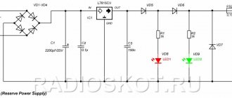
Schematic diagram of power supply unit RIP
In the proposed backup power supply (RPS) circuit, a moisture-proof transformer is used, but you can use any other 20-40 Watt, with an output voltage of 15-18 Volts. If there is only one car actuator under load, then a less powerful transformer will do. For several electric locks, the electrolytic capacitor C1 must have a higher capacitance than that indicated in the diagram - for a greater energy reserve when triggered and, accordingly, a smaller voltage drop across the load. Capacitor C2 – 0.1-0.33mF, C3 – 0.1-0.15mF. The radiator for IC1 is larger, about 100-150 cm2, since in a case with a battery, extra heating is not needed! The output load current for L7815CV is 1.5A. Moreover, if a plastic box is used as a housing, do not forget about the ventilation holes. Diode D8 and fuse FS2 serve as short circuit protection.
Security RIPs have a tamper button against unauthorized hacking of the device - we don’t need it. On the board, to connect wires, it is better to use soldering instead of terminals, as the most reliable method of fastening. Also, it is appropriate to play it safe and take the spare power wiring out of the room, in case of an unforeseen event (stuff happens in life).
How to connect an intercom with an electromagnetic lock
Connecting an intercom with a magnetic lock is extremely simple. This applies to both video intercom and voice communication devices. For installation, follow the steps given in the description of the diagram.
A simple description of the installation diagram
An intercom with a magnetic locking mechanism consists of a handset unit and a monitor. They are located indoors or at home.
The power supply, batteries and service module can be installed anywhere. It is highly recommended to do this closer to the handset to reduce the length of the cables.
The removal panel is placed wherever the owner wishes. It is best to install it in such a way as to protect it from damage and moisture. To connect, you need to lay the wires in advance.
The electromagnetic lock is mounted in 2 ways. They differ in the method of landing on the door leaf. The first consists of a cutout with overlays of durable body parts on the surface of the sash. The second involves installation in the inner cavity of the door with the magnetic pad brought to the surface.
Connection of electromagnetic lock and intercom
The purchased product may have a different number of contacts. When a manufacturer uses standard markings, the colors of the taps will correspond to:
- green - responsible for basic control and release;
- black - zero terminal for status monitoring;
- blue and yellow - transmit a closing or opening signal.
An intercom with an electromagnetic lock does not use detailed monitoring. The locking mechanism is connected with only 2 contacts. Green controls the calling panel. Red is connected to the positive circuit of the power supply of the required voltage. All the necessary information is present in the technical data sheet that comes with the product.
Assembling components on a printed circuit board
To make the device work and look decent, we will use printed circuit boards. For assembly you will need:
- Printed circuit board
- Arduino Pro Mini
- 12V power supply
- DC connector
- Electromagnet 12 V
- RC522 module
- Relay HLS8L-DC5V-SC
- Resistor 4.7 kOhm 2 pcs.
- 1N5819 diodes
- Capacitor 100 nF
- Voltage stabilizer 5 V
- 2-pin ARK connectors 2 pcs.
- BC557C transistor
- RGB diodes with common cathode
The elements are attached to the board as shown in the picture and soldered. In addition to the soldered elements, we install Pro Mini and RC522 using connectors. The entire board should look like this:
After assembling the board, we can select a place on the wall where the electronic lock kit will be located. We drill 5 holes, as in the case - one larger one for the wires to the other side of the wall, four smaller ones for the screws in the dowels. After drilling, we can secure the lower part of the body with self-tapping screws. All that remains is to screw the electromagnet - both parts to the door and frame with short screws.
Installation instructions and connection diagrams
When purchasing an electromagnetic lock and subsequent installation, it is worth remembering a number of features characteristic of different types of door leaves. Below we will look at the main options.
Entrance metal door
Before starting work, prepare and lay out suitable tools. You will need a tape measure, a building level, pliers, a hammer, and wire cutters. Also prepare a pencil, drill and screwdriver.
Depending on the type of box, mounting brackets may be required. It’s good if you have on hand a core, a tap and other products necessary for installing an electromagnetic lock in metal doors.
The main fastening element of the EMZ is a cylinder with a special cap that rests on the door plane from the outside.
During the installation process, you need to mark the installation location, drill a hole for the diameter of the screw, and drill a hole for the diameter of the bushing on the outside of the door.
It is important to make sure that the bushing fits into a larger diameter hole from the outside of the door and rests against the metal sheet on the other side. The holes on the bushing and the inside of the doors must line up exactly with each other.
It happens that even with correct markings difficulties arise. They are often caused by a discrepancy between the length of the sleeve and the thickness of the door leaf.
Therefore, if the sleeve is long, it will not be possible to completely hide it. Otherwise, the mounting screw may not reach the threads.
The options may be as follows:
It is advisable to place a rubber washer between the door leaf and the “iron”, which ensures reliable contact and the necessary backlash.
EMZ equipped with a controller
Autonomous controllers are used in conjunction with EMS to restrict access to residential apartment buildings, administrative institutions and industrial facilities. An electromagnetic lock with a controller can be used in a single system with the following equipment:
- contact and contactless key readers;
- normally open lock opening buttons;
- external LEDs and buzzers;
- open door sensors;
- input inversion jumper, which allows you to open doors both by applying and removing voltage.
Also, an EMZ equipped with a controller is compatible with a PC, which maintains a database of keys and also performs their prompt change, both unloading and loading.