In this article, we will look at a number of simple and not so simple circuits, thanks to which you can assemble an LED driver with your own hands. We previously started a thread about this. However, a large number of readers asked for a more extensive article without “water” and unnecessary information. In principle, our magazine tries to provide only such content.
So let's begin. The article will be long, so be patient and let’s get started.
All the schemes discussed below can be assembled by literally anyone, and “on their knees.” Of course, it’s easier to buy ready-made drivers, especially for pennies, but it’s much more interesting to assemble it yourself.
—> —>
Background
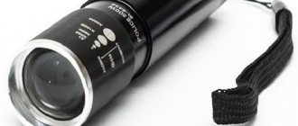
Once upon a time, I ordered a flashlight with a bright LED from a Chinese website. The flashlight turned out to be quite ergonomic (although it could have been lighter), but its driver left much to be desired.
It shone quite brightly, but the driver had only 3 modes - very bright, bright and strobe, switching between which was done by pressing a button. In order to simply turn the flashlight on and off, it was necessary to go through these 3 modes each time. In addition, this flashlight, when turned on, drained the battery to the last - so a couple of my 18650 cans went into a deep discharge.
All this was inconvenient and annoying, so at some point I decided to make my own driver for it, which will be discussed further.
Flashlight with an old driver
Here is a flashlight, many have probably dealt with similar ones
This is what the original driver looks like
Technical task
As you know, to achieve a good result, any development must have a good technical specification, so I will try to formulate it for myself. So the driver should:
- Be able to turn on/off by briefly pressing a button (non-latching button). Perhaps this is the main reason why all this started.
- Have a smooth (stepless) brightness adjustment, from the brightest - “turbo”, to “moonlight”, when the diode barely glows. The brightness should change evenly.
- Remember the set brightness during shutdown.
- Monitor the battery charge, warning when it is almost discharged (approximately 3.3V) and turning off when completely discharged (approximately 2.9V). For different batteries, these parameters may be different. Accordingly, the operating voltage should be in the range of 2.7~4.5V.
- Have 2 special modes - emergency beacon and strobe (well, why not?)
- Be able to turn on/off the rear LED (this is important when riding a bicycle at night, it turns out something like a side light).
- Have protection against polarity reversal and static electricity. Not necessary, but it will be a nice addition, since in the dark you can mistakenly place the battery on the wrong side.
- Be smaller in size than the original driver, but have the same seats. The Chinese driver is simply huge; making it bigger will not be easy.
Well, if the flashlight is modded, why not build into it a charger with a micro-USB connector? I always have such a cable and USB charging at hand, but I have to look for my own power supply.
Iron
I have some experience with Arduino, so it was decided to make a driver for the AVR family of MKs. They are widely available, easy to program, and have low power (sleep) modes.
The Attiny13a microcontroller was chosen as the “brain” of the driver - this is one of the cheapest MCUs from Atmel (now absorbed by Microchip), it has everything necessary on board - GPIO for connecting a button and an LED, a timer for generating a PWM signal, an ADC for measurement voltage and EEPROM for saving parameters. Only 1 KB of flash memory is available (but how much is needed for a flashlight), as well as 64 B of RAM and the same amount of EEPROM. Attiny13 is available in several package options, in particular in DIP-8, which can be plugged directly into a regular development board with a pitch of 2.54mm.
Since there are only 3 wires going from the back to the head of the flashlight, the button is forced to short to ground (we will talk about the impossibility of shorting to positive later), you will have to switch the LED to positive - which means you need a P-channel field switch. As such a transistor, I took AO3401, but you can take SI2323, it is more expensive, but has a lower open-channel resistance (40 mOhm, whereas the AO3401 has 60 mOhm, at 4.5 V), therefore the driver will heat up less.
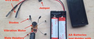
From words to action, I’m putting together a preliminary version on a breadboard
For now, it is powered directly from the programmer, with a voltage of 5 V (actually less due to losses in the USB cable). Instead of the XM-L LED, for now I plugged in a regular LED on legs and installed a weak transistor with a high threshold voltage. Then a circuit was drawn in Altium Designer, which I added with reverse polarity and ESD protection.
Detailed description and purpose of all components
Required components:
U1 – Attiny13a microcontroller in 8S1 package (SSU index)
C1 – decoupling capacitor for microcontroller power supply, should be around 0.1 uF, case 1206 or 0805, temperature coefficient X7R
R1-R2 is a resistor divider for measuring battery voltage, you can set any ratings, the main ratio here is (750K/220K, division factor 4.41) and the leakage current, which will be greater if you increase the ratings (at current values it is about 4 μA). Since an internal ION is used (1.1 V, according to the datasheet it can be in the range of 1.0 V - 1.2 V), the maximum voltage at the divider output should not be more than 1 V. With a 750/220 divider, the maximum allowable voltage at the divider input will be 4.41 V, which more than enough for all types of lithium batteries. I calculated the divisor using this calculator.
R3 - protection of the microcontroller port output from short circuit (if suddenly PB1 is pulled to VCC, a large current will flow through the pin and the MK may burn out)
R4 - pulls up the RESET MK to the power supply; without it, reboots from interference are possible.
Q1 - P-channel field-effect transistor in the SOT-23 package, I installed AO3401, but you can use any other one with a suitable pinout (for example SI2323)
R7 is the gate current limiting resistor. Since the gate of the transistor has some capacitance, when this capacitance is charged, a large current can pass through the pin and the pin can fail. You can set it in the region of 100-220 Ohms (you shouldn’t go any further, the transistor will begin to remain in a half-closed state for a long time, and, as a result, it will heat up more).
R6 - gate pull-up resistor to power supply. In case PB0 goes into a high impedance state, a logical 1 will be established through this resistor at the gate of Q1 and the transistor will be turned off. This can happen due to an error in the code or programming mode.
D2 - “blocking” diode - allows you to power the MK from the capacitor for some time during a voltage “sag” (when the LED turns on for a short period at full brightness), and also protects against polarity reversal. You can install any Schottky diode in a SOD323 package with a minimum voltage drop; I installed a BAT60.
Initially, protection against reverse power polarity was made on a field-effect transistor (this can be seen on boards made by loot). After desoldering, an unpleasant feature emerged - when the load was turned on, a voltage drop occurred and the MK rebooted, since the field device does not limit the current in the opposite direction. I first soldered a 200uF electrolytic capacitor between VCC and GND, but I didn't like this solution due to its size. I had to unsolder the transistor and put a diode in its place, since SOT-23 and SOD-323 have similar sizes.
In total, the circuit contains only 10 components that are required for installation.
Optional components:
R5 and D1 are responsible for the backlight (LED2). The minimum rating of R5 is 100 ohms. The higher the value, the weaker the rear LED glows (it turns on in constant mode, without PWM). D1 - any LED in the 1206 housing, I put green because visually they are brighter at the same currents than others.
D3 and D4 are protection diodes (TVS), I used PESD5V0 (5.0V) in a SOD323 package. D3 protects against overvoltage via power supply, D4 – via button. If the button is covered with a membrane, then it doesn’t make much sense. It probably makes sense to use bidirectional protective diodes, otherwise, when the polarity is reversed, current will flow through them and they will burn out (see I-V characteristics of a bidirectional protective diode).
C2 is a tantalum capacitor in case A (similar to 1206), it makes sense to install it when the driver is unstable (the supply voltage of the micron can sag at high LED switching currents)
All resistors are size 0603 (for me this is an adequate limit for hand soldering)
Everything is clear with the components, you can make a printed circuit board according to the above diagram. The first step is to build a 3D model of the future board, along with the holes - IMHO, in Altium Designer this is the most convenient way to determine the geometry of the PCB. I measured the dimensions of the old driver and its mounting holes - the board should be attached to them, but have smaller dimensions (for versatility, in case it has to be built somewhere else). A reasonable minimum here turned out to be somewhere around 25x12.5mm (aspect ratio 2:1) with two holes with a diameter of 2mm for attaching to the flashlight body with original screws.
I made the 3D model in SolidWorks, then exported it to Altium Designer as STEP. Then I placed the components on the board, made the contacts in the corners (this makes it more convenient to solder and easier to connect the ground), placed Attiny13 in the center, the transistor closer to the LED contacts. I routed the power traces, placed the remaining components as needed and routed the signal traces. To make it easier to connect the charger, I placed separate contacts for it that duplicate the battery contacts. I did all the wiring (except for one jumper) on the top layer so that I could make the board at home using LUT. The minimum width of signal traces is 0.254 mm / 10 mil, power traces have a maximum width where possible.
This is what a routed board looks like in Altium Designer
Altium Designer allows you to see what the board will look like in 3D (for this you need to have models for all components, some of which you had to build yourself). Perhaps someone here will say that the 3D mode for the tracer is not needed, but for me personally this is a convenient feature that makes it easier to place components for easy soldering.
At the time of writing, 3 versions of the board were made - the first for LUT, the second for industrial production and the 3rd, final version with some corrections.
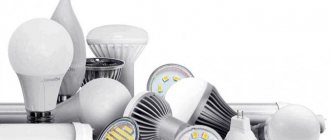
What are the types of drivers for LEDs by device type?
Drivers for LEDs are classified by device type into linear and pulsed. The structure and typical driver circuit for linear-type LEDs is a current generator on a transistor with a p-channel. Such devices provide smooth current stabilization under the condition of unstable voltage on the input channel. They are simple and cheap devices, but they are low efficient, generate a lot of heat during operation and cannot be used as drivers for high-power LEDs.
Pulse devices create a series of high-frequency pulses in the output channel. Their operation is based on the PWM (pulse width modulation) principle, when the average output current is determined by the duty cycle, i.e. the ratio of the pulse duration to the number of its repetitions. The change in the average output current occurs due to the fact that the pulse frequency remains unchanged, and the duty cycle varies from 10-80%.
Due to the high conversion efficiency (up to 95%) and compactness of the devices, they are widely used for portable LED designs. In addition, the efficiency of the devices has a positive effect on the duration of operation of autonomous power devices. Pulse-type converters are compact in size and have a wide range of input voltages. The disadvantage of these devices is the high level of electromagnetic interference.
Helpful advice! You should purchase an LED driver at the stage of selecting LED sources, having previously decided on a circuit of LEDs from 220 volts.
LED driver efficiency reaches 95%
Before choosing a driver for LEDs, you need to know the conditions of its operation and the location of the LED devices. Pulse-width drivers, which are based on a single microcircuit, are miniature in size and are designed to be powered from autonomous low-voltage sources. The main application of these devices is car tuning and LED lighting. However, due to the use of a simplified electronic circuit, the quality of such converters is somewhat lower.
Manufacturing of boards
Homemade method
LUT is a laser-iron technology, a method of producing circuit boards using etching on a mask obtained by transferring toner from paper to copper. This method is great for simple single-sided boards, such as this driver. There are quite a lot of articles on this technology on the Internet, so I will not go into details, but will only briefly tell you how I do it.
First you need to prepare a template that will be printed on thermal paper. I export the top_layer layer to PDF and get a vector image.
Since the board is small, it makes sense to take a piece of PCB with dimensions several times larger and do what is called panelization in the industry. CorelDraw is very convenient for these purposes, but you can use any other vector editor. I place copies of the templates on the document, make gaps of 0.5-1 mm between the boards (depending on the method of separation, more on that later), the boards must be located symmetrically - otherwise it will be difficult to separate them.
I select a piece of one-sided PCB slightly larger in size than the assembled panel, clean it and degrease it (I prefer to rub it with an eraser and then with alcohol). I print a template for etching on thermal paper (here it is important not to forget to mirror the template). Using an iron and patience, gently stroking the paper, I transfer it to the textolite. I wait until it cools down and carefully peel off the paper. Free areas of copper (not covered with toner) can be varnished or sealed with tape (the smaller the area of copper, the faster the etching reaction occurs).
This is home panelization - a large number of boards allows you to compensate for manufacturing defects
I etch boards with citric acid in a hydrogen peroxide solution, this is the most accessible method, although rather slow. The proportions are as follows: for 100 ml of 3% peroxide there are 30 g of citric acid and about 5 g of salt, this is all mixed and poured into a container with textolite. Warming the solution will speed up the reaction, but may cause the toner to peel off.
An unknown chemical magic begins: the copper becomes covered with bubbles, and the solution takes on a blue tint.
After some time, I take out the etched board and clean it of toner. I can’t wash it off with any solvents, so I remove it mechanically with fine-grained sandpaper.
Now all that remains is to tin the board - this will help with soldering and will protect the copper from oxidation and make soldering easier. I prefer to tin with Rose alloy - this alloy melts at a temperature of about 95 degrees, which allows it to be tinned in boiling water (yes, it may not be the most reliable composition for tinning, but it is suitable for homemade boards).
After tinning, I drill the board (for contacts I use carbide drills f1.0, for jumpers - f0.7), I drill with a Dremel in the absence of another tool. I don’t like sawing PCB because of the dust, so after drilling I cut the boards with a utility knife - I make several cuts along one line on both sides, then break them along the cut. This is similar to the V-cut method used in industry, but the cut is made with a cutter.
This is what the board looks like ready for soldering
When the board is ready, you can start unsoldering the components. First I solder the small stuff (0603 resistors), then everything else. The resistors are adjacent closely to the MK, so soldering them in reverse order can be problematic. After soldering, I check if there is a short circuit in the driver power supply, after which I can start flashing the MK firmware.
Drivers ready for firmware download
Industrial method
LUT is fast and affordable, but the technology has its drawbacks (like almost all “home” methods for making PP). It is problematic to make a double-sided board; the tracks can be etched, and metallization of the holes can only be a dream.
Fortunately, enterprising Chinese have long been offering industrial printed circuit board manufacturing services. Oddly enough, a single-layer board from the Chinese will cost more than a two-layer one, so I decided to add a second (bottom) layer to the PCB. The power traces and ground are duplicated on this layer. Also, it became possible to make a heat sink from the transistor (copper polygons on the bottom layer), which will allow the driver to operate at higher currents.
Bottom layer of the board in Altium Designer
For this project, I decided to order a printed circuit board from the PcbWay website. The website has a convenient calculator for calculating the cost of boards depending on their parameters, sizes and quantities. After calculating the cost, I uploaded the gerber file created earlier in Altium Designer, the Chinese checked it and the board went to production.
It cost me $5 to make a set of 10 TinyFL boards. When registering as a new user, you get a $5 discount on your first order, so I only paid for shipping, which also costs somewhere around $5. On this site it is possible to put the project in the public domain, so if someone wants to order these boards, they can simply add this project to the cart.
A couple of weeks later I received the same boards, only beautiful ones made in an industrial way. All that remains is to unsolder them and fill them with firmware.
Where to buy drivers for LEDs
You can buy LED-drivers at specialized points selling radio components. In addition, it is much more convenient to familiarize yourself with the products and order the necessary product using the catalogs of the relevant sites. In addition, in online stores you can purchase not only converters, but also LED lighting devices and related products: power supplies, control devices, connection tools, electronic components for repair and DIY LED driver assembly.
The cost of the driver can reach 300 rubles and more
Selling companies offer a huge range of drivers for LEDs, the technical characteristics and prices of which can be seen in the price lists. As a rule, product prices are indicative and are specified when ordering from the project manager. The range includes converters of various powers and degrees of protection, used for external and internal lighting, as well as for illumination and tuning of cars.
When choosing a driver, you should take into account the conditions of its use and the power consumption of the LED design. Therefore, it is necessary to purchase a driver before purchasing LEDs. So, before you buy a driver for 12 volt LEDs, you need to take into account that it should have a power reserve of about 25-30%. This is necessary in order to reduce the risk of damage or complete failure of the device due to a short circuit or voltage surges in the network. The cost of the converter depends on the number of devices purchased, form of payment and delivery time.
The table shows the main parameters and dimensions of 12 volt voltage stabilizers for LEDs, indicating their estimated price:
| Modification LD DC/AC 12 V | Dimensions, mm (h/w/d) | Output current, A | Power, W | price, rub. |
| 1x1W 3-4VDC 0.3A MR11 | 8/25/12 | 0,3 | 1x1 | 73 |
| 3x1W 9-12VDC 0.3A MR11 | 8/25/12 | 0,3 | 3x1 | 114 |
| 3x1W 9-12VDC 0.3A MR16 | 12/28/18 | 0,3 | 3x1 | 35 |
| 5-7x1W 15-24VDC 0.3A | 12/14/14 | 0,3 | 5-7x1 | 80 |
| 10W 21-40V 0.3A AR111 | 21/30 | 0,3 | 10 | 338 |
| 12W 21-40V 0.3A AR11 | 18/30/22 | 0,3 | 12 | 321 |
| 3x2W 9-12VDC 0.4A MR16 | 12/28/18 | 0,4 | 3x2 | 18 |
| 3x2W 9-12VDC 0.45A | 12/14/14 | 0,45 | 3x2 | 54 |
Program (firmware)
The main difficulty that arose when writing the driver firmware was related to the extremely small size of flash memory - Attiny13 has only 1024 bytes. Also, since the change in brightness is smooth, changing it evenly turned out to be a non-trivial task - for this we had to do a gamma correction.
Driver control algorithm
The driver is turned on by briefly pressing the button, and turned off by the same button. The selected brightness mode is saved during shutdown.
If during operation you make a double short press of the button (double click), the additional LED will be turned on/off. If you press it for a long time during operation, the brightness of the flashlight will gradually change. Repeated long press changes direction (stronger/weaker).
The driver periodically checks the battery voltage, and if it is below the set values, it warns the user about the discharge, and then turns off to avoid deep discharge.
A more detailed description of the driver operation algorithm
- When power is supplied to the MK, the peripherals are configured and the MK goes into sleep (if STARTSLEEP is defined). When power is applied to the driver, both LEDs flash a number of times if STARTBLINKS is defined.
- Dream. Attiny13 falls asleep in power-down mode (this is the most economical mode; according to the datasheet, the consumption of the MK will be ~ 1 µA), from which it can only exit due to some interruption. In this case, this is the INT0 interrupt - pressing a button (setting PC1 to logical 0). On PC1, the internal weak power pull-up must be turned on. The ADC and comparator are the main current consumers of all peripherals, so they also need to be turned off. During sleep, the contents of the registers and RAM are saved, so EEPROM is not needed to remember the brightness.
- After sleep, the peripherals and PWM are turned on and the driver enters an endless loop, in which button presses are monitored and the battery voltage is periodically checked.
- If the button is pressed, the pressing time is recorded. 4.1. If the press is short, a double click is expected (if BTN_DBCLICK is defined). If it was, the additional LED LED2 switches. If not, then go to step 2 (sleep) 4.2. If you press it for a long time (longer than BTN_ONOFF_DELAY), the brightness control mode is turned on. In this mode:
- Inverts the direction of change (more/less) and changes the PWM fill % while the button is pressed.
- If the maximum/minimum value (RATE_MAX / RATE_MIN) is reached, the LED starts flashing;
- If n-blinks have passed (AUXMODES_DELAY) and the button is still pressed, the additional mode is activated. There are two such modes - a strobe (turns on for 25 ms, frequency 8 Hz) and an emergency beacon (turns on at full brightness for 50 ms, frequency 1 Hz). In these modes, there is no battery charge check, and to exit you need to hold the button down for a while.
- If it’s time to check the battery voltage, the readings are read from ADC2 and the result is compared with the preset values.
- If the ADC value is greater than the BAT_WARNING value, everything is fine
- If BAT_WARNING is less, the user is warned about the discharge, the driver blinks the main LED. The number of flashes will be proportional to the degree of discharge. For example, with default values, when fully discharged, the flashlight will blink 5 times.
- If BAT_SHUTDOWN is less, the MK goes to step 2 (sleep).
LED brightness control
As you know, the easiest way to control brightness is to change the PWM duty cycle, in which the LED turns on at full brightness for a while, then turns off. Due to the characteristics of the human eye, the LED appears to shine less brightly than if it were constantly on. Since the LED is connected through a P-channel field-effect transistor, to open it, you need to pull the gate to ground, and to close it, vice versa, to power. The time the transistor is on relative to the time it is off will correlate with the PWM fill. The rate variable is responsible for the duty cycle of the PWM, 255 rate = 100% PWM. With a clock frequency of 1.2 MHz and a timer prescaler of 1, the PWM frequency will be equal to 1200000/256 = 4.7 KHz. Since this is an audio frequency (perceived by the human ear), at a certain duty cycle the PWM driver may begin to squeak (more precisely, it is not the driver that squeaks, but the wires or batteries). If it interferes, you can increase the operating frequency to 9.6 (CKSEL[1:0]=10, CKDIV8=1) or 4.8 MHz (CKSEL[1:0]=01, CKDIV8=1), then the PWM frequency will be 8 or 4 times more, but the energy consumption of the MK will also increase proportionally.
It is believed that the diode must be powered by stabilizing the current through it, and in this mode it will quickly fail. Here I agree and say that in my flashlight (and in many headbands of a similar design) the LED is not connected directly to the driver, but rather long and thin wires go to it, the resistance of which, as well as the internal resistance of the battery and the resistance of the driver, is limited the maximum current is around 1.5 A, which is 2 times less than the maximum current for this LED (the maximum current for Cree XM-L according to the documentation is 3 A). If your driver is connected to the LED with short wires and the battery holder has good contacts, the current at maximum brightness (rate=255) can exceed 3A. In this case, this driver most likely will not suit you, since there is a risk of the LED failing. However, you can adjust the RATE_MAX parameter until acceptable current values are obtained. In addition, although according to the specification of the SI2323DS transistor its maximum current exceeds 4 A, it is better to set the threshold to 2 A, otherwise the driver may require cooling.
Gamma correction
The human eye perceives the brightness of objects nonlinearly. In the case of this driver, the difference between 5-10% PWM will be perceived as a multiple increase in brightness, while the difference between 75-100% will be practically invisible to the eye. If you increase the brightness of an LED evenly, at a rate of n percent per second, the brightness will initially appear to increase very quickly from zero to the average value, then increase very slowly from the middle to maximum.
This is very inconvenient, and to compensate for this effect we had to create a simplified gamma correction algorithm. Its essence is that the brightness change step increases from 1 at minimum PWM values to 12 at maximum values. In graphical representation, this looks like a curve, the points of which are stored in the rate_step_array. Thus, the brightness appears to vary evenly over the entire range.
Battery voltage monitoring
Every n-seconds (the BAT_PERIOD parameter corresponds to the interval in milliseconds), the battery voltage is measured. The positive contact of the battery, which is connected to VIN and goes to the resistor divider R1-R2, to the middle point of which pin PB4 is connected (aka ADC2 for the ADC multiplexer).
Since the supply voltage changes along with the measured voltage, it will not be possible to measure it using Vref as a reference voltage, so I used an internal 1.1 V source as a reference voltage. This is exactly what a divider is for - the MK cannot measure a voltage greater than voltage reference source (so, a voltage of 1.1 V will correspond to an ADC value of 1023 or 255 if you use 8-bit resolution). Passing through the divider, the voltage at its midpoint will be 6 times less than the input, the value of 255 will no longer correspond to 1.1 V, but as much as 4.33 V (divisor by 4.03), which covers the measurement range with a margin.
As a result, a certain value is obtained, which is then compared with the preset values of the minimum voltages. When the BAT_WARNING value is reached, the LED begins to blink a certain number of times (the more discharged, the more it blinks - BAT_INFO_STEP is responsible for this, more details in the code), and when BAT_SHUTDOWN is reached, the driver is turned off. I don’t see any point in converting the ADC value into millivolts, because This wastes extra memory, of which there is already little in Tinka.
By the way, the divider is the main power consumer when the MK is in sleep mode. So, a divider by 4.03 with R1 = 1M and R2 = 330K will have a total R = 1330K and a leakage current at 4 V = 3 µA. While the voltage is being measured, the load (LED) is turned off for approximately 1 ms. This is almost invisible to the eye, but it helps to stabilize the voltage, otherwise the measurements will be incorrect (and it is too difficult to make any corrections for the pulse duty cycle, etc.).
Making changes to the firmware
This is not difficult to do, especially if you have experience with Arduino or just C/C++. Even if you have no such experience, you can customize almost all operating parameters by editing the definitions of the flashlight.h header file. To edit the source code, you will need to install an Arduino IDE with support for Attiny13(a) or Atmel Studio - it is no more complicated than the Arduino IDE, but much more convenient.
Arduino IDE
First you will need to install Attiny13 support in the IDE. Quite detailed instructions are available in this article. Next you need to select Tools>Board Attiny13(a) in the menu and Tools>Frequency 1.2MHz in the menu. The “sketch” is contained in a file with the .ino extension; it contains only one line of code - this is the inclusion of a header file in the project. Essentially, this sketch is just a way to compile the firmware through the Arduino IDE. If you want to make any changes to the project, work with the .cpp file. After opening the project, you need to click on the checkbox, compilation will begin, and if successful, there will be a link to the *.hex file in the log. It needs to be poured into the microcontroller according to the instructions below.
Atmel Studio
The project for this IDE is contained in the file flashlight.atsln, and the sources are contained in the files flashlight.h contains definitions (settings) and flashlight.cpp contains the actual code. I don’t see any point in describing the contents of the source code in more detail - the code is full of comments. After making changes to the code, you need to press F7, the firmware will compile (or not, then the compiler will indicate where the error is). Flashlight.hex appears in the debug folder, which can be loaded into the microcontroller according to the instructions below.
Uploading firmware to the microcontroller
To download the firmware and configure the fuse, I use the USBASP programmer in combination with the AVRDUDEPROG program. The program is like a GUI for the avrdude program, there is a convenient built-in fuse calculator - just check the boxes next to the required bits. In the list of controllers you need to select the appropriate one (in this case Attiny13(a), go to the Fuses tab and press the read button. Only after the fuse values are read from the MK, you can change them. After the change you need to press programm, the new fuses will be written to MK Suitable fuse values are written in the flashlight.h file
To upload the firmware, go to the Program tab, select the compiled firmware file in HEX format (flashlight.hex) in the Flash line and click Program. The firmware status will be displayed in the window below. If the download is unsuccessful, it may be due to poor contact, this happens - it’s worth trying again. By the way, this is precisely why the STARTBLINKS parameter was made - a single blink of LED2 at the moment power is supplied to the driver serves as an indication of contact between the driver and the programmer. Instead of USBASP, you can use Arduino to download the firmware, more details here and here
USBASP programmer connected to the driver via a clip with a cable
To connect USBASP to Tink, I use a clip for an 8-pin SOIC. It’s not a very convenient device; you have to struggle for about 10 minutes before you get the contact (perhaps I just got a defective clip). There are also SOIC-DIP adapters, where a microcircuit is inserted before soldering and the firmware is poured into it - this option is more convenient, but the ability to program the driver in-circuit is lost (that is, update the firmware after soldering the MK to the board). If all this is missing, then you can simply solder the wires to the MK pins, which are then attached to the Arduino.
Calibration
The currents passing through the driver and LED must not exceed the maximum values. For an XM-L LED this is 3 A, for a driver it depends on the transistor used, for example for SI2323 the maximum current is about 4 A, but it is better to drive at lower currents due to excessive heating. To reduce the current at maximum brightness, use the RATE_MAX parameter (#define RATE_MAX xx, where xx is the maximum brightness from 0 to 255). Calibrating the ADC is not a mandatory procedure, but if you want the driver to accurately track the threshold voltage, you will have to tinker with it.
Calculations will not give high measurement accuracy, because firstly, resistor values can vary within tolerance (usually 1-5%), and secondly, the internal ionizer can have a spread from 1.0 to 1.2 V. Therefore, the only acceptable The way is to set the value in ADC units (BAT_WARNING and BAT_SHUTDOWN), experimentally selecting it to suit the needs. This requires patience, a programmer and a regulated power supply. I set the BAT_PERIOD value in the firmware to 1000 (checking the voltage once per second) and gradually reduced the supply voltage. When the driver started to warn about a discharge, I left the current value of BAT_WARNING as desired. This is not the most convenient way; perhaps in the future it is necessary to perform an automatic calibration procedure with saving values in EEPROM.
LED Driver Circuits
Many manufacturers produce driver chips for LEDs that allow the sources to be powered from a reduced voltage. All existing drivers are divided into simple ones, made on the basis of 1-3 transistors, and more complex ones using special microcircuits with pulse width modulation.
Driver circuit for 1W LEDs
ON Semiconductor offers a wide selection of ICs as the basis for drivers. They are distinguished by reasonable cost, excellent conversion efficiency, cost-effectiveness and low level of electromagnetic pulses. The manufacturer presents a pulse-type driver UC3845 with an output current of up to 1A. On such a chip you can implement a driver circuit for a 10W LED.
Electronic components HV9910 (Supertex) is a popular driver chip due to its simple circuit resolution and low price. It has a built-in voltage regulator and outputs for brightness control, as well as an output for programming the switching frequency. The output current value is up to 0.01A. On this chip it is possible to implement a simple driver for LEDs.
Based on the UCC28810 chip (made by Texas Instruments), you can create a driver circuit for high-power LEDs. In such an LED driver circuit, an output voltage of 70-85V can be created for LED modules consisting of 28 LED sources with a current of 3 A.
Helpful advice! If you are planning to buy ultra-bright 10 W LEDs, you can use a switching driver based on the UCC28810 chip for designs made from them.
Power LED connection diagram
Clare offers a simple pulse-type driver based on the CPC 9909 chip. It includes a converter controller housed in a compact housing. Due to the built-in voltage stabilizer, the converter can be powered from a voltage of 8-550V. The CPC 9909 chip allows the driver to operate under conditions of a wide range of temperature conditions from -50 to 80°C.
Flashlight assembly
When the board was ready and the firmware was uploaded, it was finally possible to install it in place of the old driver. I unsoldered the old driver and soldered a new one in its place.
The new driver is connected instead of the old one according to this scheme
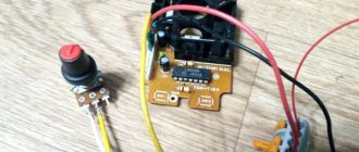
After checking to see if there was a short circuit in the power supply, I connected the power and checked the functionality. Then I mounted the charging board (TP4056), for this I had to drill out the hole in the charging connector a little with a Dremel, and fixed it with hot glue (it was important here that the glue did not leak into the connector, it would be difficult to get it out of there).
I did not fasten the board with screws, because the threads in the case had broken off from repeated tightening, but simply filled it with glue, and also sealed the wires at the solder points so that they would not fray. I decided to coat the driver and charger with clear acrylic varnish, this should help against corrosion.
Testing and manufacturing cost calculation
After all the operations, you could start testing the drivers. The current was measured with a conventional multimeter, connecting it to the power supply circuit.
Power consumption of the old driver (measured at 4.04 V):
- During sleep - not measured
- Maximum mode: 0.60 A
- Medium mode: 0.30 A
- Strobe: 0.28 A
Power consumption of the new driver (measured at 4.0 V):
- In sleep mode, it consumes around 4 µA, which is much less than the self-discharge current of a lithium-ion battery. The main current in this mode flows through the resistor divider.
- At the minimum mode, “moonlight” is about 5-7 mA, if we assume that the capacity of one 18650 cell is about 2500 mAh, then we get about 20 days of continuous operation . The MK itself consumes somewhere around 1.2-1.5 mA (at an operating frequency of 1.2 MHz).
- At maximum mode, “turbo”, it consumes about 1.5 A, in this mode it will work for about an hour and a half. The LED at such currents begins to heat up very much, so this mode is not intended for long-term operation.
- Emergency beacon - consumes an average of about 80 mA, in this mode the flashlight will work for up to 30 hours.
- Strobe light - consumes about 0.35 A, will work for up to 6 hours.
Price issue
If you buy components in Chip and Deep, it will cost about 100 rubles (60 rubles Attiny13, ~40 rubles for the rest of the bulk). It makes sense to order from China if you are making several pieces - then it will be cheaper per piece; the Chinese usually sell in batches of 10 pieces. The boards will cost around 300 rubles for 10 pieces (without delivery) if you order them in China. Wiring and flashing one driver takes me about an hour.
Description of functions
- There are 4 modes: 40, 170, 680, 2300 mA. Switching modes is carried out by short-term <1 sec, turning off the power. The 40 mA mode is done by PWM, for reasons of squeezing maximum LED efficiency.
- Battery discharge monitoring - when it drops below 2.75 V, the circuit goes into sleep mode.
- Battery charge indicator, 5 levels. When double-clicked during operation (power interruption), it flashes from 1 (discharged) to 5 (fully charged) times.
- Smooth start of the scheme.
- Possibility to enable thermal control. To do this you need to calibrate.