Instrumental search is simply enormously popular. Adults and children, amateurs and professionals are looking for it. They are looking for treasures, coins, lost things and buried scrap metal. The main search tool is a metal detector .
There are a great variety of different metal detectors to suit every taste and color. But for many people, buying a ready-made branded metal detector is simply financially expensive. And some people want to assemble a metal detector with their own hands, and some even build their own small business on their assembly.
Metal detector N. Martynyuk
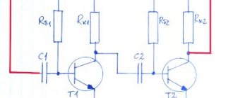
The metal detector according to N. Martynyuk’s scheme (Fig. 1) is made on the basis of a miniature radio transmitter, the radiation of which is modulated by an audio signal [Рл 8/97-30]. The modulator is a low-frequency generator made according to the well-known symmetrical multivibrator circuit.
The signal from the collector of one of the multivibrator transistors is fed to the base of the high-frequency generator transistor (VT3). The operating frequency of the generator is located in the frequency range of the VHF-FM broadcast range (64... 108 MHz). A piece of television cable in the form of a coil with a diameter of 15...25 cm was used as the inductor of the oscillating circuit.
Rice. 1. Schematic diagram of N. Martynyuk’s metal detector.
If a metal object is brought closer to the inductor of the oscillating circuit, the generation frequency will noticeably change. The closer the object is brought to the coil, the greater the frequency shift will be. To record frequency changes, a conventional FM radio receiver is used, tuned to the frequency of the HF generator.
The receiver's automatic frequency control system should be disabled. If there is no metal object present, a loud beep is heard from the receiver's speaker.
If you bring a piece of metal to the inductor, the generation frequency will change and the volume of the signal will decrease. The disadvantage of the device is its reaction not only to metal, but also to any other conductive objects.
How to assemble a metal detector with your own hands at home
7 simple steps:
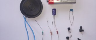
- In order to assemble a metal detector, we will need a Chinese radio receiver (must have a magnetic antenna, AM range), a cheap calculator, a box and double-sided tape.
- We unfold the box so that it has the shape of a book (the main part on one side, the lid on the other)
- We glue the radio and calculator to the book with double-sided tape. (the radio is attached to the lid, and the calculator is attached to the base of the box).
- We turn on the receiver and find a frequency segment that is not used by radio stations (about 1.5 MHz).
- Let's start working with the calculator. At the same time, the radio receiver begins to make loud noise.
- We begin to slowly bring the box lid closer to the main part. We need to find a position where the noise disappears.
- We fix the book in this position. Ready! You have made the simplest amateur metal. detector.
Metal detector based on a low-frequency LC generator
In Fig. 2 - 4 shows a circuit of a metal detector with a different operating principle, based on the use of a low-frequency LC oscillator and a bridge frequency change indicator. The search coil of the metal detector is made in accordance with Fig. 2, 3 (with correction of the number of turns).
Rice. 2. Metal detector search coil.
Rice. 3. Metal detector search coil.
The output signal from the generator is fed to a bridge measuring circuit. A high-resistance telephone capsule TON-1 or TON-2 is used as a bridge null indicator, which can be replaced with a pointer or other external alternating current measuring device. The generator operates at frequency f1, for example, 800 Hz.
Before starting work, the bridge is balanced to zero by adjusting the capacitor C* of the oscillating circuit of the search coil. The frequency f2=f1 at which the bridge will be balanced can be determined from the expression:
Initially, there is no sound in the telephone capsule. When a metal object is introduced into the field of the search coil L1, the generation frequency f1 will change, the bridge will become unbalanced, and a sound signal will be heard in the telephone capsule.
Rice. 4. Diagram of a metal detector with an operating principle based on the use of a low-frequency LC generator.
Main settings
To determine the appropriate criteria for a homemade design, it is necessary to study the basic technical parameters.
Detection depth
The principle of operation of the metal detector
This data is not always provided in the accompanying documentation. Even when the depth is indicated in the technical data sheet, this value should not be understood as a certain value. The fact is that for control measurements they use a uniform soil composition and maintain stable temperature and humidity. In a real situation, natural and other external factors will significantly worsen the results obtained under ideal conditions.
For your information. High-quality factory metal detectors are capable of detecting a product made of conductive material at a depth of 1.5-3 m. “Deep” modifications operate up to a maximum of 5-6.5 meters.
Operating frequency
You can increase the search depth by using a reduced frequency. In this case, the selectivity of the work process is significantly deteriorated. However, long waves bend around small objects, which is accompanied by a deterioration in sensitivity.
For your information. In professional metal detectors, the user can choose from more than two dozen different frequencies. With such equipment, the choice of the optimal research mode under certain conditions is simplified.
Metal detector bridge circuit
The bridge circuit of a metal detector using a search coil that changes its inductance when metal objects approach is shown in Fig. 5. An audio frequency signal from a low-frequency generator is supplied to the bridge. Using potentiometer R1, the bridge is balanced for the absence of an audio signal in the telephone capsule.
Rice. 5. Bridge circuit of a metal detector.
To increase the sensitivity of the circuit and increase the amplitude of the bridge unbalance signal, a low-frequency amplifier can be connected to its diagonal. The inductance of the L2 coil should be comparable to the inductance of the L1 search coil.
Metal detector based on a receiver with the CB range
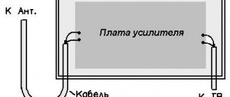
A metal detector operating in conjunction with a mid-wave superheterodyne radio broadcast receiver can be assembled according to the circuit shown in Fig. 6 [R 10/69-48]. The design shown in Fig. 1 can be used as a search coil. 2.
Rice. 6. A metal detector operating in conjunction with a superheterodyne radio receiver in the CB range.
The device is a conventional high-frequency generator operating at 465 kHz (the intermediate frequency of any AM broadcast receiver). The circuits presented in Chapter 12 can be used as a generator.
In the initial state, the frequency of the HF generator, mixing in a nearby radio receiver with the intermediate frequency of the signal received by the receiver, leads to the formation of a difference frequency signal in the audio range. When the generation frequency changes (if there is metal in the field of action of the search coil), the tone of the sound signal changes in proportion to the amount (volume) of the metal object, its distance, and the nature of the metal (some metals increase the generation frequency, others, on the contrary, lower it).
Idea
The easiest design for me to make on my own seemed to be this: take a disk made of sheet material ~4-6 mm thick. The diameter of this disk is determined by the diameter of the future winding (in my case it should be 21 cm).
Then we glue two disks of slightly larger diameter to this pancake on both sides to make a bobbin for winding wire. Those. such a coil greatly increased in diameter, but flattened in height.
For clarity, I’ll try to depict this in a drawing:
I hope the main idea is clear. Just three disks glued together over the entire area.
A simple metal detector with two transistors
Rice. 7. Scheme of a simple metal detector using silicon and field-effect transistors.
The diagram of a simple metal detector is shown in Fig. 7. The device uses a low-frequency LC generator, the frequency of which depends on the inductance of the search coil L1. In the presence of a metal object, the generation frequency changes, which can be heard using the BF1 telephone capsule. The sensitivity of such a scheme is low, because It is quite difficult to detect small changes in frequency by ear.
Principle of operation
The operating principle of the detectors is based on the law of electromagnetic induction. The key element in the device is the coil. It generates EMF to evaluate surfaces. The electronic unit processes the received signal and sends a message to the user about the presence of conductive objects.
The lower rod fixes the reel and adjusts its tilt level. The middle structure acts as an intermediate link between the upper and lower rods. It changes the position of the structure for ease of use.
On top there is a block and a handle with armrests for convenient operation. The EMF is generated by the coil. If it interacts with a conductive object, the device emits a characteristic visual or vocal alert.
The principle of operation of a metal detector.
Briefly about geoscanners
Geoscanners are powerful search devices that can determine the shape of an object and the depth of its occurrence in the soil. They are popular among experienced treasure hunters because they support flexible settings and require some skill to operate.
Modern devices are capable of generating pulses with a transmitter, processing signals from a receiver, and synchronizing the operation of equipment. The main parts of a georadar: antenna, recording unit and control unit.
Metal indicator circuit
A different method of indicating the presence of metal is used in the device according to the diagram in Fig. 9. The device contains a high-frequency generator with a search coil and operates at frequency f1. To indicate the signal magnitude, a simple high-frequency millivoltmeter is used.
Rice. 9. Schematic diagram of a metal indicator.
It is made on diode VD1, transistor VT1, capacitor C1 and milliammeter (microammeter) PA1. A quartz resonator is connected between the output of the generator and the input of the high-frequency millivoltmeter. If the generation frequency f1 and the frequency of the quartz resonator f2 coincide, the needle of the device will be at zero. As soon as the generation frequency changes as a result of introducing a metal object into the field of the search coil, the needle of the device will deviate.
The operating frequencies of such metal detectors are usually in the range of 0.1...2 MHz. To initially set the generation frequency of this and other devices of similar purpose, a variable capacitor or a tuning capacitor connected in parallel with the search coil is used.
Typical metal detector with two generators
In Fig. Figure 10 shows a typical diagram of the most common metal detector. Its operating principle is based on the frequency beats of the reference and search oscillators.
Rice. 10. Diagram of a metal detector with two generators.
Rice. 11. Schematic diagram of the generator block for a metal detector.
A similar node, common to both generators, is shown in Fig. 11. The generator is made according to the well-known “three-point capacitive” scheme. In Fig. Figure 10 shows a complete diagram of the device. The design shown in Fig. 1 is used as search coil L1. 2 and 3.
The initial frequencies of the generators must be the same. The output signals from the generators through capacitors C2, SZ (Fig. 10) are fed to a mixer that selects the difference frequency. The selected audio signal is fed through the amplifier stage on transistor VT1 to the telephone capsule BF1.
Material selection
I planned to use plexiglass as the material. It is perfectly processed and glued with dichloroethane. But, unfortunately, I couldn’t find it for free.
All sorts of collective farm materials such as plywood, cardboard, bucket lids, etc. I immediately discarded them as unsuitable. I wanted something strong, durable and preferably waterproof.
And then my gaze turned to fiberglass...
It's no secret that fiberglass (or glass mat, fiberglass) is used to make whatever your heart desires. Even motor boats and car bumpers. The fabric is impregnated with epoxy resin, given the desired shape and left until completely cured. The result is a durable, water-resistant, easy-to-handle material. And this is exactly what we need.
So, we need to make three pancakes and ears for attaching the barbell.
Metal detector based on the principle of generation frequency interruption
The metal detector can also operate on the principle of disrupting the generation frequency. The diagram of such a device is shown in Fig. 12. If certain conditions are met (the frequency of the quartz resonator is equal to the resonant frequency of the oscillatory LC circuit with the search coil), the current in the emitter circuit of transistor VT1 is minimal.
If the resonant frequency of the LC circuit changes noticeably, the generation will fail, and the readings of the device will increase significantly. It is recommended to connect a capacitor with a capacity of 1 ... 100 nF in parallel to the measuring device.
Rice. 12. Circuit diagram of a metal detector that works on the principle of disrupting the generation frequency.
What parts can be replaced and with what?
Transistors : BC546 – 3 pcs or KT315. BC556 – 1 piece or KT361 Op amps :
LF353 – 1 piece or exchange for the more common TL072. LM358N – 2 pcs Digital chips: CD4011 – 1 pc CD4066 – 1 pc CD4013 – 1 pc Fixed resistors, power 0.125-0.25 W: 5.6K – 1 pc 430K – 1 pc 22K – 3 pcs 10K – 1 pc 390K – 1 pc 1K – 2 pcs 1.5K – 1pc 100K – 8pcs 220K – 1pc 130K – 2pcs 56K – 1pc 8.2K – 1pc Variable resistors: 100K – 1pc 330K – 1pc Non-polar capacitors: 1nF – 1pc 22nF – 3pcs (22000pF = 22nF = 0.022uF) 22 0nF – 1 piece 1uF – 2 pieces 47nF – 1 piece 10nF – 1 piece Electrolytic capacitors: 220 µF at 16V – 2 pieces
The speaker is miniature. Quartz resonator at 32768 Hz. Two ultra-bright LEDs of different colors.
If you cannot get imported microcircuits, here are domestic analogs: CD 4066 - K561KT3, CD4013 - 561TM2, CD4011 - 561LA7, LM358N - KR1040UD1. The LF353 microcircuit has no direct analogue, but feel free to install LM358N or better TL072, TL062. It is not at all necessary to install an operational amplifier - LF353, I simply increased the gain to U1A by replacing the resistor in the negative feedback circuit of 390 kOhm with 1 mOhm - the sensitivity increased significantly by 50 percent, although after this replacement the zero went away, I had to glue it to the coil in a certain place tape a piece of aluminum plate.
Soviet three kopecks can be sensed through the air at a distance of 25 centimeters, and this is with a 6-volt power supply, the current consumption without indication is 10 mA. And don’t forget about the sockets - the convenience and ease of setup will increase significantly. Transistors KT814, Kt815 - in the transmitting part of the metal detector, KT315 in the ULF. It is advisable to select transistors - 816 and 817 with the same gain. Replaceable with any corresponding structure and power. The metal detector generator has a special clock quartz at a frequency of 32768 Hz. This is the standard for absolutely all quartz resonators found in any electronic and electromechanical watches. Including wrist and cheap Chinese wall/table ones. Archives with a printed circuit board for the Volksturm SMD version and for the Volksturm+GEB (version with manual ground detuning).
Metal detectors for searching for small objects
Metal detectors, designed to search for small metal objects in everyday life, can be assembled according to those shown in Fig. 13 - 15 schemes.
Such metal detectors also operate on the principle of generation failure: the generator, which includes a search coil, operates in a “critical” mode.
The operating mode of the generator is set by adjusted elements (potentiometers) so that the slightest change in its operating conditions, for example, a change in the inductance of the search coil, will lead to disruption of the oscillations. To indicate the presence/absence of generation, LED indicators of the level (presence) of alternating voltage are used.
Inductors L1 and L2 in the circuit in Fig. 13 contain, respectively, 50 and 80 turns of wire with a diameter of 0.7...0.75 mm [Fs 8/75]. The coils are wound on a 600NN ferrite core with a diameter of 10 mm and a length of 100... 140 mm. The operating frequency of the generator is about 150 kHz.
Rice. 13. Circuit of a simple metal detector with three transistors.
Rice. 14. Scheme of a simple metal detector using four transistors with light indication.
Inductors L1 and L2 of another circuit (Fig. 14), made in accordance with the German patent (No. 2027408, 1974), have 120 and 45 turns, respectively, with a wire diameter of 0.3 mm [P 7/80-61 ]. A 400NN or 600NN ferrite core with a diameter of 8 mm and a length of 120 mm was used.
Household metal detector
A household metal detector (HIM) (Fig. 15), produced earlier (Moscow), allows you to detect small metal objects at a distance of up to 45 mm. The winding data of its inductors are unknown, however, when repeating the circuit, you can rely on the data given for devices of similar purposes (Fig. 13 and 14).
Rice. 15. Scheme of a household metal detector.
Literature: Shustov M.A. Practical circuit design (Book 1), 2003