This post is an introduction to my project of a “homemade” video console made from scratch. I was inspired by both retro consoles and modern designs, but I came up with my own architecture. My friends constantly told me that I should talk about my project, and not do everything exclusively “for myself,” so here I am publishing this post.
Attention, this is a translation
My name is Sérgio Vieira, I grew up in Portugal in the 80s and 90s, I have long had a nostalgia for retro gaming, especially third and fourth generation consoles.
A few years ago I decided to understand electronics better and try to make my own set-top box.
I am a programmer by profession and had no experience as an electronics engineer, except (and this should not be counted) for independent upgrades of my desktop computer.
Although I had no experience, I said to myself “why not?”, bought several books, several electronics kits and began to study based on my feelings about what exactly was worth studying.
I wanted to make a console similar to those that give me nostalgic feelings, I wanted something between the NES and the Super Nintendo, or maybe between the Sega Master System and the Mega Drive.
These consoles had a CPU, an original video chip (they weren't called GPUs back then) and an audio chip, sometimes built-in and sometimes external.
Games were distributed on cartridges, which were generally extensions of the hardware, sometimes just ROM chips, and sometimes had additional components.
The original plan was to make a console with the following characteristics:
- Without emulation, games and programs must run on real hardware, not necessarily the same hardware from back in the day, but fast enough for the task and nothing more.
- With a real retro CPU.
- With analog TV output.
- With sound
- Supports two controllers
- Scrolling backdrops and sprite animation
- With capabilities to support platform games like Mario, and of course all sorts of other games.
- With loading games and programs from SD cards.
Why SD cards and not cartridges, well, basically it’s just much more practical, they can be copied from a computer. And cartridges would mean, firstly, more hardware in the console, and secondly, the production of hardware for each program.
Video signal
The first thing I did was generate a video signal.
Any console from the period I sampled had different proprietary graphics chips, meaning they all had different specifications. For this reason, I did not want to use an off-the-shelf graphics chip; I wanted my console to have unique graphics specifications. And since I could not make my own graphics chip, and at that time did not yet know how to use an FPGA, I decided to limit myself to software generation of the graphics signal using an 8-bit, 20 megahertz microcontroller.
This is not overkill, and just a powerful enough solution for graphics of the level that was interesting to me.
So, I started using the Atmega644 microcontroller at 20 MHz to generate a PAL video signal for the TV. I had to bit-ban the PAL protocol, since the chip itself does not support it.
The microcontroller produces 8-bit color (RGB332, 3 bits red, 3 bits green and 2 bits blue) and the passive DAC converts it all to RGB. Luckily in Portugal almost all TVs are equipped with a SCART connector and they support RGB input.
Roadmap for assembling Dendy with your own hands
The diagram, if anyone has read to the assembly stage) To open in full expansion, on the image that opens, right-click - open in a new tab and then left-click +.
First thing
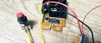
We solder the 60-pin connector and check how all its 60 contacts ring along the tracks to the places where each contact arrives. Almost half leads to CPU, the other half to PPU. Power supply and outputs from the generator.
Second thing
We are putting together a power supply diagram. Power connector, diode bridge, stabilizer with radiator, capacitors before and after the stabilizer, power button and reset button. We supply power and check all the last legs on all microcircuits for the presence of a stable supply of +5 volts. The last leg of the chip is +, the minus is on the opposite side at the end of the chip.
Third thing
We assemble a circuit for a sound amplifier and image output. After assembly, you can check the functionality of the cascade by touching the outputs of the left and right channels from the CPU, pins 1 and 2. When you touch them with your hand, a quiet noise should appear at the output of the audio amplifier. On your TV, if you have connected the red and white output to the audio input)
By touching the outputs from PPU pin 21 on the TV when the yellow cable is connected to the video input, small ripples will appear.
Fourth thing
We solder all the parts and carriages for the microcircuits onto the board. We check each soldered part three times: the nominal value, how it was soldered, and we rang it in place.
Fifth thing
We insert all the microcircuits into place. And we try to run it without a cartridge. A square should appear on the screen, called a raster. Well, and some strange crunching sound when turned on. Turn it on.
Insert the cartridge and turn it on.
Long torment with a tambourine and a thorough check of soldering leads to the launch of this device)
Yellow - cascade of audio and video amplifiers and outputs.
Red - power supply details of the circuit.
Blue - frequency generator - to change the frequency from PAL to NTSC, only the quartz, PPU and CPU are changed.
Finally, I will describe the main problems that I learned on the forum and that I have encountered myself:
The main problem: there is a picture, the game is running on the screen, there are artifacts - a broken PPU, there is no way to fix it, only replace it with a previously stable one for testing.
The second reason
There is power, but nothing starts at all HELP.
There are a lot of reasons)
First and foremost: SOLDERING. Check all parts for functionality 10 times before soldering.
Second: microcircuits. Very often purchased micrs are not compatible with Chinese 400-game katrikas. Processing speed is not enough. Check performance on old cartridges that are still in use. They have 5 volt micros and the speed is slower than on the new Chinese multi-game machines. In my case, the reason the Coolboy cartridge did not start was in the SN74HC139N chip. On the drops, all the katrics worked, but the new 400 in 1 did not start until I changed it.
Correct graphics subsystem
Since the microcontroller is quite powerful, and I decided to use it exclusively to generate a video signal (I called it VPU - Video Processing Unit), I decided to organize a double buffer at the same time.
It turned out that the second microcontroller (PPU, Picture Processing Unit, Atmega1284 chip, also at 20 MHz) generated a picture into RAM chip number 1 (I called it VRAM1), and the first at the same time sent the contents of the second chip (VRAM2) to the TV.
After one frame, and two frames in the PAL system is 1/25 of a second, the VPU switches VRAMs and they change places, the PPU generates a picture in VRAM2, and the VPU dumps VRAM1 to the TV output.
The video board turned out to be very complex because I had to use external hardware so that both microcontrollers could use both memory modules and to speed up access to RAM, because there is also bit banging, so I had to add 74 series chips as counters, line selectors, transceivers, etc. .
The firmware for VPU and PPU also turned out to be cumbersome because we had to write a lot of code to squeeze maximum speed out of the graphics. At first everything was written in assembler, then some was rewritten in C.
As a result, the PPU generates a 224x192 pixel image, which is then sent to the TV via the VPU. The resolution may seem low to you, but actually it's almost as high as the consoles of that time actually had, usually 256x224. A slightly lower resolution allowed me to add more features that the system can calculate in one frame.
Just like in the old days, PPU has its own tough mechanics that you need to know how to use. The background (back) is rendered from 8x8 pixel characters, also called tiles. It turns out that the size of the background is 28x24 tiles.
So that the back could scroll smoothly, pixel by pixel, I made it so that there are 4 virtual screens in total, each with 28x24 tiles that go in memory sequentially and are wrapped around each other, this is clearer in the picture.
On top of the background, the PPU can render 64 sprites that can be 8 or 16 pixels in height or width, that is, 1, 2 or 4 tiles and can also be flipped horizontally and/or vertically.
On top of the back, you can also render one buffer of 28x6 tiles as an overlay; this was intended for drawing HUDs and speeds so as not to interfere with the main sprites and scrolling of the back.
One “advanced” feature is that the back can be scrolled not entirely, but each line separately, which allows for all sorts of interesting effects like split screen or almost-parallax.
There is also an attribute table that allows you to set each tile a value from 0 to 3, and then you can set all tiles with one attribute to a page of tiles or increment their symbolic value. This is convenient when there are parts of the backing that need to be changed regularly and the CPU does not have to calculate each tile separately, it just needs to say something like: “all tiles with attribute 1, increment the numerical value of your symbol by 2”, similar things can be implemented using different techniques observe, for example, in block tiles in Mario where the question mark is animated or in games where there is a waterfall in which all the tiles are constantly changing creating the effect of falling water.
What you need for a full-fledged retro console
First of all, let's decide on the list of necessary peripherals, software and everything that is needed to bring a “second life” to an old piece of hardware.
— Actually, the laptop or PC itself. Of course, a worker, with ancient Windows XP or a tired “Seven”. The power of the device practically does not matter. If it runs Windows XP, at least one USB port works and there is an output to an external monitor, the candidate is ready for transformation.
- USB flash drive. The volume here directly affects the number of games that you can install. If native Sega or Dendy toys take up 100 - 200 KB, then with CD images from the first generation Sony PlayStation everything is a little more serious. Distributions take up from 300 MB to 700 – 800 MB. In a word, the more memory a flash drive has, the better.
- Gamepad, or better yet two. Absolutely any controller with a USB port will do: even from a famous one for a couple of hundred rubles. If you want to have a real battle, buy a couple at once.
— External monitor or TV + appropriate cable and adapter. Everything here is strictly individual. If you have HDMI, you need an appropriate cable that fits your TV. DVI or VGA - it doesn’t matter, the main thing is to get the picture from the laptop to be displayed on the TV screen.
However, having an external monitor is not necessary, although it is highly desirable. It's much more pleasant to experience a feeling of nostalgia on the big screen.
CPU
When my video card started working, I started working with the CPU, which was Zilog 80 for my set-top box.
One of the reasons why the Z80 was chosen, well, besides the fact that it is a cool retro CPU, is its ability to address two 16-bit spaces, one for memory and the second for I/O ports, the no less legendary 6502, for example, cannot do this , it can only address one 16-bit space and you have to map both memory and various external devices, video, audio, joysticks, hardware random number generator, etc. into it. It is more convenient to have two address spaces, one completely dedicated to 64 kilobytes of code and data in memory, and the second for accessing external devices.
First, I connected the CPU to the EEPROM in which my test program was located and also connected it through the I/O space to the microcontroller that I installed so that I could communicate with my computer via RS232 and monitor how the CPU and everything else was working. I call this Atmega324 microcontroller operating at 20 MHz IO MCU - input/output microcontroller unit, it is responsible for controlling access to game controllers (joysticks), SD card reader, PS/2 keyboard and communicator via RS232.
The CPU is connected to a 128 kilobyte memory chip, of which only 56 kilobytes are available, this is of course nonsense, but I could only get 128 or 32 kilobyte chips. It turned out that the memory consists of 8 kilobytes of ROM and 56 kilobytes of RAM.
After that, I updated the IO MCU firmware using this library and I now have support for SD card reader.
Now the CPU could walk through directories, see what was in them, open and read files. All this is done by writing and reading to specific addresses in the I/O space.
Setting up the set-top box
Of course, the main thing is to teach Raspberry to work with a suitable gamepad. Wired models almost always start out of the box; of the wireless ones, my Dualshock 3 connected right away; the rest had to be manually configured from the system parameters.
You can connect up to five gamepads, I think this is unnecessary, because most old games were designed for 1-4 players.
The key settings you need to do are:
1. Switch the interface to Russian. Main Menu (Enter on the keyboard) – System settings – Language. “A” key is used to confirm actions .
2. Connect to your home Wi-Fi network for easy downloading of games. Main menu – Network settings, activate the item Enable Wi-Fi , enter the home network name and password.
3. Configure the web interface. After connecting to the network, remember the IP address and enter it in the browser on your computer.
The system comes pre-installed with several games for different consoles, but many supported systems do not appear in the menu. Don't worry, those consoles for which no games are downloaded are hidden. Just drop the relevant data into the desired folder and the console will appear in the main menu.
The remaining parameters can be configured as desired.
Connecting CPU to PPU
The next thing I did was the communication between the CPU and PPU. To do this, I used a “simple solution” which consisted in purchasing a dual-port RAM, this is a RAM chip that can be connected to two different buses at once. This allows you to get rid of additional chips like line selectors and, moreover, allows almost simultaneous access to memory from both chips. The PPU can also directly access the CPU on each frame by activating its non-maskable interrupts. It turns out that the CPU receives an interrupt on every frame, which is useful for various timing tasks and for understanding when it’s time to update the graphics.
Each frame of interaction between the CPU, PPU and VPU occurs according to the following scheme:
- The PPU copies information from the PPU memory to the internal memory.
- The PPU sends an interrupt signal to the CPU.
- Simultaneously:
- The CPU jumps to the interrupt function and begins updating the PPU memory with the new graphics state. The program must return from the interrupt before the next frame.
- The PPU renders the image based on information previously copied to one of the VRAMs.
- The VPU sends the picture from another VRAM to the TV output.
Around the same time I started supporting game controllers, at first I wanted to use controllers from Nintendo, but the sockets for them are proprietary and generally difficult to find, so I settled on 6-button controllers compatible with Mega Drive/Genesis, they have standard DB-9 sockets which are everywhere.
Adding dynamic graphics
Everything was super, I had my own game console, but this was not enough for me, because in the game I had to use graphics flashed in the PPU memory and it was impossible to draw tiles for a specific game and it could only be changed by flashing the ROM. I began to think about how to add more memory so that the CPU could load symbols for tiles into it, and the PPU could then read it all from there and how to do it more simply since the console was already complex and large.
And I came up with the following: only the PPU will have access to this new memory, and the CPU will load data there through the PPU and while this loading process is happening, this memory cannot be used for drawing, but it will be possible to draw from the ROM at this time.
After the end of loading, the CPU will switch the internal ROM memory to this new memory, which I called Character RAM (CHR-RAM) and in this mode the PPU will start drawing dynamic graphics, this is probably not the best solution, but it works. As a result, the new memory was installed at 128 kilobytes and can store 1024 characters of 8x8 pixels each for the background and the same number of characters for sprites.
Select the operating system on which the console will run
After selecting the components, you should decide on the operating system of the future console. At the moment, there are three good assemblies that are suitable for our task:
Lakka is a build with a beautiful PlayStation-style visual interface. The project is developing rather slowly, Lakka still has many glitches and shortcomings. RecalBox is a more advanced all-in-one solution. After installation, the image will already contain a couple of dozen classic games for different platforms. In addition, the KODI . In a couple of clicks, you can turn your gaming console into a media processor for playing video from a removable drive, from the Internet or network storage. It is possible to set up IPTV.
RetroPie is another multifunctional emulator of old game consoles. Initially, the image does not include games and there is no media player like KODI, however, it is possible to install RetroPie on top of the native operating system for Raspberry - Raspbian . This means that the gaming service can work on Malinka simultaneously with other services, for example, with HomeBridge, which connects smart gadgets in the house.
The choice is between the last two options. RecalBox is a simple image with games out of the box and the KODI media center, and RetroPie is for those who want to tinker and install the system on top of Raspbian.
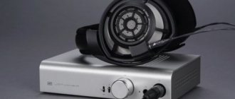
And finally the sound
The hands reached the sound last. At first I wanted a sound similar to what is in Uzebox, that is, for the microcontroller to generate 4 channels of PWM sound.
However, it turns out that I can easily get hold of vintage chips and I ordered some YM3438 FM synthesis chips, these guys are fully compatible with the YM2612 used in the Mega Drive/Genesis. By installing them you can get Mega Drive quality music and sound effects produced by the microcontroller.
I installed another microcontroller and called it SPU (Sound Processor Unit), it controls the YM3438 and can generate sounds itself. The CPU controls it through dual-port memory, this time it is only 2 kilobytes.
Like the graphics block, the sound block has 128 kilobytes of memory for storing PCM samples and sound patches, the CPU loads data into this memory by accessing the SPU. It turns out that the CPU either tells the SPU to execute commands from this memory or updates the commands for the SPU every frame.
The CPU controls four PWM channels through four circular buffers located in the SPU memory. The SPU passes through these buffers and executes the commands written to them. There is also one such buffer for the FM synthesis chip.
In total, as in the graph, the interaction between the CPU and SPU proceeds according to the diagram:
- The SPU copies data from the SPU memory to the internal memory.
- The SPU is waiting for an interrupt signal from the PPU (this is for synchronization)
- Simultaneously
- The CPU updates the PWM channel buffers and FM synthesizer buffers.
- The SPU executes commands in buffers according to data in internal memory.
- At the same time as all this, the SPU updates the PWM sounds at a frequency of 16 kilohertz.
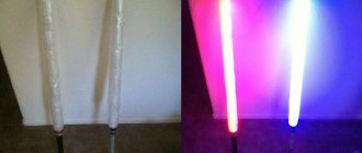
After all the blocks were ready, some went to breadboards. For the CPU block I was able to develop and order a custom PCB, I don’t know if it’s worth doing this for the other modules, I think I was actually lucky that my PCB worked right away.
On the breadboard now (for now) there is only sound left. Here's what it looks like today:
Find a balanced board for mounting Dendy with your own hands.
More precisely, find board grabbers made by professionals. There are such people. I would like to express my gratitude to Hardvarych from the emu-land.net and everyone who participated in the project to adapt and configure the board for Junior .
This is what the finished board looks like. I ordered it from Chinese friends with ALI. She arrived within 2 weeks. I ordered 10 pieces, 11 arrived. For that I thank them. In Moscow, they offered to make such a board at 4 times more expensive. It fits perfectly into a standard case and has a stereo audio output. The microcircuits are positioned optimally for desoldering and reducing the length of the tracks.
The grabbers themselves are for etching, board version 01. There is a newer one, only the location of one capacitor is different. I consider this modification not a new version. I won't post it. I assembled it according to version 01, everything is fine, it works and fits perfectly into a standard case.
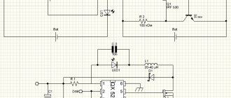
Architecture
The diagram illustrates the components in each block and how they interact with each other. The only thing that is not shown is the signal from the PPU to the CPU on each frame in the form of an interrupt and the same signal that goes to the SPU.
- CPU: Zilog Z80 at 10 MHz
- CPU-ROM: 8KB EEPROM, contains bootloader code
- CPU-RAM: 128KB RAM (56KB available), code and data for programs/games
- IO MCU: Atmega324, is the interface between the CPU and RS232, PS/2 keyboard, joysticks and SD card file system
- PPU-RAM: 4 kilobytes of dual-port memory, intermediate memory between the CPU and PPU
- CHR-RAM: 128KB RAM, stores dynamic tiles for the background (background) and sprites (in 8x8 pixel characters).
- VRAM1, VRAM2: 128KB RAM (43008 actually available), used for framebuffer, PPU writes to them and VPU reads from them.
- PPU (Picture Processing Unit): Atmega1284, draws the frame into the framebuffer.
- VPU (Video Processing Unit): Atmega324, reads the framebuffer and generates RGB and PAL signal and synchronization.
- SPU-RAM: 2KB dual-port RAM, serves as an interface between the CPU and SPU.
- SNDRAM: 128KB RAM, stores PWM patches, PCM samples and instruction blocks for the FM synthesizer.
- YM3438: YM3438 FM synthesis chip.
- SPU (Sound Processing Unit): Atmega644, generates sounds using the principle of pulse-width modulation (PWM) and controls the YM3438.
Installing the operating system on the game console
Installation of the gaming system on an already running Raspbian is done through the terminal. We’ll leave this for the future; now we’ll try the option for beginners. All the emulators described above are installed in the same way.
To get started, I recommend trying RecalBox . Here is the most clear and user-friendly interface, the setup is extremely simple, most of the features are included out of the box, and as a bonus we get the KODI , which can easily replace a budget TV set-top box for watching movies from a flash drive, over the network or online.
1. Download the selected image from the developer’s website.
2. Download and install the Etcher application to write an image to a memory card.
3. We write the image to the memory card.
4. After finishing recording, install the memory card in the Raspberry and connect it to the TV.
During the first launch, the system will be installed and the initial configuration will take place. Nothing is required from the user, we just wait a few minutes before the visual shell starts.
The system will immediately prompt you to configure the joystick. This can be either a USB accessory or a wireless one. It is better to have a keyboard at hand in order to make all the settings in case of problems connecting the gamepad.
Final Specifications
CPU:
- 8-bit CPU Zilog Z80 at 10Mhz.
- 8KB ROM for bootloader.
- 56KB RAM.
IO:
- Reading data from FAT16/FAT32 SD card reader.
- Read/write to RS232 port.
- 2 MegaDrive/Genesis-compatible game controllers.
- PS2 keyboard.
Video:
- Resolution 224x192 pixels.
- 25 frames per second (half FPS of PAL).
- 256 colors (RGB332).
- 2x2 virtual background (448x384 pixels), with bidirectional pixel-by-pixel scrolling, based on four full-screen pages.
- 64 sprites with a width and height of 8 or 16 pixels with the possibility of both vertical and horizontal flip.
- The background and sprites consist of characters of 8x8 pixels each.
- Character video memory with 1024 characters for background and 1024 for sprites.
- 64 independent horizontal scrolling along specified lines
- 8 independent vertical scrolling along specified lines
- Overlay 224x48 pixels with optional color key transparency.
- Background attribute table.
- RGB and composite PAL via SCART connector.
Sound:
- PWM 8 bits and 4 channels, with built-in waveforms: square, sine, saw, noise, etc.
- Samples at 8 bits, 8 KHz in one of the PWM channels.
- YM3438 FM synthesis chip loaded with instructions at a frequency of 50 hertz.
A bootloader was written for the console. The bootloader is placed in the CPU ROM and can occupy up to 8 kilobytes. It uses the first 256 bytes of RAM. The bootloader is the first thing the CPU executes. It is needed to show programs located on the SD card.
These programs are found in files that contain compiled code and may also contain graphics and sound.
After selecting a program, it is loaded into CPU memory, CHR memory and SPU memory. After which the program code is executed. The maximum size of the code loaded into the console is 56 kilobytes, except for the first 256 bytes, and of course you need to take into account the space for the stack and data. Both this bootloader and other programs written for this console were created in the same way as described below.
Unofficial retro consoles
Before we start talking about unofficial devices, it is worth making an important note: most of them are in the so-called gray zone. They are not prohibited in themselves, but the included game images are pirated software. Cybersport.ru does not support the activities of hackers and pirates. By downloading hacked games, you deprive the developers of profits - buy licensed copies in official stores.
Android family (from ₽2,000 and above)
1/2
One of the most common devices on the market is a slightly modified version of Android Box with an external shell for games. Most often, such devices come with two cheap DualShock 2 style gamepads and a TV remote. A big advantage of such devices is their “omnivorous” nature: many emulators have been released on Android, and Console X is capable of playing applications from 60 different devices. Of course, the issue of performance remains: on cheaper and weaker devices, gamers are unlikely to be able to run games from consoles more advanced than PS1, but in some cases (as, for example, in the case of the Beelink GT-King, equipped with 4 GB of RAM), you can count on more less sane game even in titles from PSP or Dreamcast.
RetroPie family (from ₽5,000 and above)
1/2
Today there are many devices on the market built on the Raspberry Pi board. You can purchase the board yourself and assemble the device from scratch: there are a lot of tips on the Internet for all stages, from assembling and installing software to creating custom cases. Supported platforms include devices ranging from the Atari 2600 to the Sony PSP (and if you use the Pi 4, all the way up to the SEGA Dreamcast). Self-assembly is cheaper, but more difficult to operate. However, all instructions are freely available, all that remains is to select the emulator kernels.
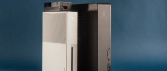
Mini PC (from ₽4,500 and above)
1/2
Recently, PC-based builds have been gaining popularity: small devices are not much larger in size than Android devices, but with the right approach, you can get a pretty convincing retro machine when assembled for under $100. By installing a special system, you can achieve both high performance and a huge library of games for every taste, both from arcades and home consoles of the early 2000s. You can also find ready-made devices with pre-installed games and emulators on sale. Words are unnecessary here: this is a familiar PC, just in a small case, with all its pros and cons. For a higher price you can buy a pretty decent device that plays games up to PS2 and Wii.
Memory/IO Mapping
What is important when developing for this console is to take into account how the CPU accesses various blocks, and correctly distribute the input/output address space and memory address space.
The CPU accesses the bootloader's RAM and ROM through the memory address space.
Memory address space
And to PPU-RAM, SPU-RAM and IO MCU through the I/O address space.
I/O address space
As can be seen from the table, within the I/O address space, addresses are allocated for all devices, IO MCU, PPU and SPU.
PPU management
From the information in the table it is clear that to control the PPU, you need to write to the PPU memory, which is available at addresses 1000h-1FFFh in the I/O address space.
PPU Address Space Allocation
PPU Status can take the following values:
- Embedded graphics mode
- Dynamic Graphics Mode (CHR-RAM)
- CHR memory recording mode
- Recording is complete, we are waiting for confirmation of the mode from the CPU
Here, for example, is how you can work with sprites: The console can draw 64 sprites at the same time. Data on them is available via the CPU through the I/O address space at addresses 1004h-1143h (320 bytes), each sprite has 5 bytes of information (5 * 64 = 320):
- A byte of different flags, each bit of this byte is a flag: Active, Flipped_X, Flipped_Y, PageBit0, PageBit1, AboveOverlay, Width16, Height16.
- Character byte, character number from the table (defined by the flags above).
- Color key byte (that is, what color is transparency)
- X coordinate byte
- Y coordinate byte
In total, to see the sprite, you need to set the Active flag to 1, and set the X and Y coordinates within visibility, coordinates 32/32 place the sprite in the upper left corner of the screen, lower values will hide it or make it partially visible.
Then we can set the character code and transparency color.
For example, if we need to show sprite number 10, then the address will be 4145 (1004h + (5 x 9)), write the value 1 for activation and coordinates, for example, x=100 and y=120, write the value 100 to address 4148 and address 4149 value 120.
Setting up a gamepad (joystick)
The gamepad needs to be configured only after you have installed the emulator you need. The media center has built-in drivers and can work with almost all known joysticks.
To configure your gamepad, open Settings, then System. Connect your device and go to the “Input” section, after “Setting up connected controllers”:
Select your joystick type and configure the button values:
That's all. As you can see, everything is simply outrageous. Did you think that your Smart TV is capable of being a game console?
If you have any questions, write in the comments and together we will solve everything.
To bookmarks
Perhaps many people have an old laptop or an obsolete computer. It’s a pity to throw away such a unit, and you won’t get any money from it on the private classifieds site.
Instead of leaving the old man collecting dust in the back corner of the closet, it can be perfectly adapted to a retro console. In this article I will talk about my own experience of turning a well-worn laptop into an excellent simulator for Sega, Dendy and PS1.
We use assembler
One of the programming methods for the set-top box is assembler.
Here's an example of how to show one sprite and animate it so that it moves and bounces off the edges of the screen.
ORG 2100h PPU_SPRITES: EQU $1004 SPRITE_CHR: EQU 72 SPRITE_COLORKEY: EQU $1F SPRITE_INIT_POS_X: EQU 140 SPRITE_INIT_POS_Y: EQU 124 jp main DS $2166-$ nmi: ; non-maskable interrupt (NMI) handler ld bc, PPU_SPRITES + 3 ld a, (sprite_dir) and a, 1 jr z, subX in a, (c) ; increase X inc a out (c), a cp 248 jr nz, updateY ld a, (sprite_dir) xor a, 1 ld (sprite_dir), a jp updateY subX: in a, (c) ; decrease X dec a out (c), a cp 32 jr nz, updateY ld a, (sprite_dir) xor a, 1 ld (sprite_dir), a updateY: inc bc ld a, (sprite_dir) and a, 2 jr z, subY in a, (c) ; increase Y inc a out (c), a cp 216 jr nz, moveEnd ld a, (sprite_dir) xor a, 2 ld (sprite_dir), a jp moveEnd subY: in a, (c) ; decrease Y dec a out (c), a cp 32 jr nz, moveEnd ld a, (sprite_dir) xor a, 2 ld (sprite_dir), a moveEnd: ret main: ld bc, PPU_SPRITES ld a, 1 out (c), a ; activate sprite 0 inc bc ld a, SPRITE_CHR out (c), a ; set the character to sprite 0 inc bc ld a, SPRITE_COLORKEY out (c), a ; set the color key for the sprite 0 inc bc ld a, SPRITE_INIT_POS_X out (c), a ; set the X coordinate of the sprite 0 inc bc ld a, SPRITE_INIT_POS_Y out (c), a ; set the Y coordinate of sprite 0 mainLoop: jp mainLoop sprite_dir: DB 0
Using the C language
We can also use the C language, for this we will need the SDCC compiler and some additional utilities.
The C code may turn out slower, but writing it is faster and easier.
Here is an example of code that does the same thing as the assembly code above, using a library that helps make calls to the PPU:
#include #define SPRITE_CHR 72 #define SPRITE_COLORKEY 0x1F #define SPRITE_INIT_POS_X 140 #define SPRITE_INIT_POS_Y 124 struct s_sprite sprite = { 1, SPRITE_CHR, SPRITE_COLORKEY, SPRITE_INIT_POS_X, SPRITE_INIT_POS_Y } ; uint8_t sprite_dir = 0; void nmi() { if (sprite_dir & 1) { sprite.x++; if (sprite.x == 248) { sprite_dir ^= 1; } } else { sprite.x—; if (sprite.x == 32) { sprite_dir ^= 1; } } if (sprite_dir & 2) { sprite.y++; if (sprite.y == 216) { sprite_dir ^= 2; } } else { sprite.y—; if (sprite.x == 32) { sprite_dir ^= 2; } } set_sprite(0, sprite); } void main() { while(1) { } }
DIY 8-bit game console?
So, we present to your attention UZEBOX !
This is a homebrew console that you can make at home.
It is based on only 2 chips - ATMega 644 and an AD725 NTSC signal encoder (optional, there is a version with a black and white image, but without this encoder)
Current features from the console developers website (without translation, so as not to play with a damaged phone):
- Low parts count and cost: The system is made of only two chips and discrete components.
- Interrupt driven kernel: No cycle counting required, sound mixing and video generation are all made in the background.
- 256 simultaneous colors: Accomplished by using a R-2R resistor ladder DAC.
- 4 channels sound engine: The sound subsystem is composed of 3 wavetable channels and 1 noise or PCM channel.
- MIDI In: With a music sequencer, allows the creation of music directly on the console.
- Retro controllers: The joypad inputs uses standard NES/SNES controllers interface.
- SNES Mouse Support
- SD/MicroSD card interface
- Expandable: I/O lines and peripherals are still available, like the UART and SPI port for one to experiment.
- Emulator: A fully, cycle-perfect, emulator was developed and greatly eases development.
- Gameloader (beta): Load and flash games stored on SD cards!
- API: Develop games using an API that provides multiple video modes, sound driver and more.
- Open Source: The software and hardware design are totally free and licensed under the GPL.
Specifications: CPU: ATmega644 microcontroller Total RAM: 4K Program Memory: 64K Speed: 28.61818Mhz (Overclocked) Colors: 256 simultaneous colors arranged in a 3:3:2 color space (Red:3 bits, Green:3 bits, Blue: 2 bits) Resolution: Up to 240×224 pixels (tiles-only and tiles-and-sprites modes) Sprites: Up to 32 simultaneous sprites on screen at any time Video output: NTSC Composite and S-Video Sound: 4 channels wavetable, 8 -bit mono, mixed at
15Khz and output via PWM Inputs: Two NES/SNES compatible joypad inputs Options: MIDI-in interface and s-video output
For those who are not familiar with electronics, you can download an emulator from the developers’ website (for Windows, SDL.dll is required) and try the console without the risk of damaging the parts.
For programmers, there is a special SDK that allows you to write games in C with convenient calls and a well-documented interface.
And now there will be slides. Clickable.
Dynamic graphics
(In the original Custom graphics. approx. per.)
The ROM of the console contains 1 page of tiles for the backing and another page of ready-made sprites), by default you can only use these fixed graphics, but you can switch to dynamic ones.
My goal was to have all the necessary graphics in binary form immediately loaded into the CHR RAM, and the code in the bootloader from ROM can do this. To do this, I made several pictures of the correct size with different useful symbols:
Since the dynamic graphics memory consists of 4 pages of 256 characters of 8x8 pixels each and 4 pages of the same characters for sprites, I converted the pictures to PNG format and deleted the same ones:
And then I used a homemade tool to convert it all into the RGB332 binary format with 8x8 blocks.
As a result, we have files with symbols, where all the symbols come sequentially one after another and each takes 64 bytes.
What's the optimization, brother?
- The characters were made smaller: small sprites - less memory.
- We optimized the graphics: instead of large repeating pictures, there are many small repeating pictures.
- We optimized the architecture of the levels: we made them symmetrical, but shifted the rows in a circle left and right to add variety.
- For additional variety, new color palettes have been introduced.
- More complex levels were not stored in their entirety in memory. Only additional traps and enemies were kept for them. And in the background lay the same old levels.
- And all this is in pure assembler.
Sound
Waveform RAW samples are converted to 8-bit 8KHz PCM samples.
Patches for PWM sound effects and music are written with special instructions.
As for the Yamaha YM3438 FM synthesis chip, I found a program called DefleMask that produces PAL-synced music and is intended for the YM2612 chip from Genesis, which is compatible with the YM3438.
DefleMask exports music in VGM format and I convert it with another home-made utility into my own binary format.
All binaries of all three audio types are combined into one binary file, which my bootloader can read and load into the SDN RAM audio memory.
Emulator
I wrote an emulator for my console in C++ using wxWidgets to make it easier to develop for it.
The CPU is emulated by the libz80 library.
Features for debugging have been added to the emulator, I can stop it at any time and do step-by-step debugging of the assembler, there is mapping to the source code in C if this language was used for the game.
From the graphics, I can look into the video memory, into the symbol tables and into the CHR memory itself.
Here is an example of a program running on an emulator with debugging tools enabled.
These videos were shot with a smartphone camera aimed at the CRT TV screen, I apologize for the imperfect picture quality.
BASIC interpreter programmable from a PS/2 keyboard, after the first program, I show how to write directly to the PPU memory through the I/O address space by activating and moving the sprite:
Graphics demo, in this video 64 16x16 sprites jump programmatically, against a background with dynamic scrolling and an overlay that moves under and above the sprites:
The sound demo shows the capabilities of the YM3438 and PWM sound, the sound data of this demo and FM music and PWM sounds together occupy almost all of the available 128 kilobytes of sound memory.
Tetris, for graphics almost only the background capabilities are used, music on the YM3438, sound effects on PWM patches.
This project is truly a dream come true, I have been working on it for several years now, intermittently, depending on my free time, I never thought that I would get so far in creating my own retro video game console. Naturally, it is not ideal, I’m certainly not an expert in electronics, there were clearly too many elements in the console and undoubtedly it could have been done better, and probably one of the readers is thinking about this.
But still, in the process of working on this project, I learned a lot about electronics, game consoles and computer design, assembly language and other interesting things, and most importantly, I got great satisfaction from playing games that I myself wrote on hardware that I myself developed and collected it.
I have plans to continue making consoles/computers. Actually, I’m already making a new set-top box, it’s almost ready, and it’s a simplified retro set-top box based on an FPGA board and several additional components, (in much smaller quantities than in this project, for sure), designed to be much cheaper and more repeatable.
Although I have written a lot here about this project, there is undoubtedly a lot more that can be discussed, I barely mentioned how the sound engine works, how the CPU interacts with it, and there is a lot more that can be said about the graphics system and other inputs and outputs and about the entire console as a whole. it would be nice to tell.
Looking at the reaction of readers, I may write more articles focusing on updates, details about individual units of the console or other projects.
Game logic
To make the game more interesting to play for longer than five minutes, the developers set the following requirements:
- This will be a platformer - a game where the main character needs to run and jump on platforms, climb up and jump over obstacles.
- The hero will be able to move deftly and shoot at enemies.
- So that you can play with a group, they make multiplayer for four people.
Since we have memory limitations, the entire game is written in Assembly - this is a language that works directly with the processor. On the one hand, Assembly code executes very quickly; on the other hand, it works stupidly with transferring data from one processor cell to another. It's like making sushi, working with individual grains of rice.
The memory was distributed like this:
- 8 kilobytes for graphics,
- 32 kilobytes for the game code itself and data storage.