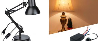
Replacing the lamp
If there is no light and the cause of the problem is only to replace a burnt out light bulb, you need to proceed as follows:
Disassemble the lamp
We do this carefully so as not to damage the device. Rotate the tube along the axis
The direction of movement is indicated on the holders in the form of arrows. When the tube is rotated 90 degrees, lower it down. The contacts should come out through the holes in the holders. The contacts of the new light bulb must be in a vertical plane and fit into the hole. When the lamp is installed, turn the tube in the opposite direction. All that remains is to turn on the power supply and check the system for functionality. The final step is the installation of a diffuser lamp.
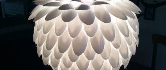
Homemade lampshades without frame
Many materials are rigid enough to hold their shape on their own, but at the same time they are flexible enough to make something interesting out of them. There are a lot of such homemade lampshades. And almost all of them are worth your attention. We will present here only part, the other part will go in the section with photos (see below).
From knitted lace doilies
Many people have crocheted napkins and they lie in “stashes”, because it’s a pity to throw them away and they don’t know how to use them. There is a very interesting idea - to make a lampshade from them for a hanging chandelier. In addition to napkins, you will need a large balloon or inflatable ball, glue for heavy wallpaper (vinyl, silk-screen printing, etc.), and a brush.
Soak the glue according to the instructions and wait until it swells. We inflate a balloon or take a ball and hang it up. When the glue is ready, lay out a napkin on some clean surface, coat it with glue, and place it on the ball.
It must be laid out in such a way that there will be a hole in the center for the cartridge. We glue the napkins one by one. They need to be laid out so that the edges overlap slightly. When all the napkins are laid out, coat them with glue again and leave until dry. When the glue has dried, deflate the ball or ball (the ball can be pierced, if you don’t mind) and take it out through the hole. That's all, the lace lampshade is ready.
In some cases, problems arise with how to hang the finished lampshade on the socket. The problem can be solved simply - take a transparent plastic bottle, cut off its neck, if necessary, expand the hole to the required size (so that it fits tightly onto the cartridge), then cut the plastic so that you get a ring 5-7 cm wide. Coat this ring with PVA glue , and glue it to the lampshade from the inside of the ball.
Round lampshades made of threads
Almost the same technology can be used to produce round and semicircular stylish lampshades. Choose threads of a suitable color. Their composition is absolutely unimportant - what matters is color, thickness and texture. They can be shaggy, smooth, twisted, thinner and thicker. The appearance depends on this. It is most convenient to work with cotton threads of medium thickness. They absorb glue well and then, after drying, keep their shape perfectly.
You will also need a ball or ball. This will be the base of the lampshade, which gives the shape. You can choose the dimensions of the base as desired. The threads will need to be glued together; for this you will need PVA glue. It is poured into a container and diluted with water in a 1:1 ratio.
You can use other glue. It is important that it becomes transparent after drying. This is WB-29 from TYTAN Professional and D2 glue for carpentry. If you use any of these types of glue, read the instructions.
On the ball or sphere we will draw a circle, which will be slightly smaller in size than the lamp socket. On the opposite side, draw a larger circle - this will be the lower edge of the lampshade. Now everything is ready, we can start.
We coat the threads with glue and wind them around the ball in a chaotic manner. It’s more convenient to do this if the glue is poured into a container - you can put the whole skein in there and just pull the thread slowly. With glue in a tube, everything is not so comfortable: you have to coat sections up to a meter long, wrap it around, and coat it again. It takes much longer. This is if you do not use PVA. But the products turn out to be more rigid and do not sag or change shape over time, as can happen with PVA thread lampshades.
When winding threads around the ball, carefully go around the drawn circles. If you accidentally climbed into the “forbidden territory”, simply move the threads, forming a smooth (more or less smooth) edge. When the threads run out or you decide that the density is enough, the process can be stopped. We tuck the edge of the thread between the others. All. Next, coat the ball with wound threads again with glue (PVA can be poured over) and leave to dry (at least 2 days). To prevent the ball from rolling, we find a bowl or pan and use it as a stand.
The last stage is to deflate the ball or ball. If the ball has a nipple, press it with a thin wire, releasing the air. We take out the deflated ball. That's all, you can thread the lamp inside and test the lampshade.
The technology is the same, but the appearance is very different...
Using the technology described above, you can make not only round lampshades. Rectangular, triangular, trapezoidal. Choose a base that is easy to remove, wind threads soaked in glue, braid, even sticks, newspaper tubes, etc. After drying, remove the base and voila, you have made a lampshade with your own hands. A couple of examples in the photo below.
You can also use chopsticks... Just wrap the ball with cling film and use transparent carpentry glue rather than PVA glue
This is a paste-like polymer clay in a tube, which was applied to a milk carton, then dried and the bag was removed...
Electronic ballast connection
How to install a water heated floor with your own hands: step-by-step installation instructions for all types of coatings (20+ Photos & Videos) + Reviews
Connecting the electronic ballast (electronic trigger)
Chokes are quite noisy devices. Therefore, in recent years they have been connected to the fluorescent lighting system infrequently, replacing them with electronic ballasts, digital or analog.
Such devices no longer need a starter. Essentially, electronic triggers are small electronic circuit boards. They themselves are able to regulate the voltage level and provide even light, without flickering. Plus they are safer and less fire hazardous in operation and have a longer service life.
There can be many options for implementing electronic ballasts, but there are two main launch methods:
- the sources are preheated; this helps increase the efficiency of the device and reduce its flicker
- using an oscillatory circuit; the filament in this case is part of it; when a discharge passes, the circuit parameters change, as a result the voltage drops to the required level
You can get rid of annoying humming and blinking by replacing the old throttle with a modern electronic ballast. To do this you should:
back to menu
Furnace in production: types, design, drawings, instructions for making it yourself (Photo & Video) + Reviews
Using lamps for greenhouse growing plants
PROS:
- The first significant advantage of such devices is significant energy savings. The latest generation of light sources operating on this principle consume 4-5 times less energy than conventional incandescent lamps.
- In addition to high light output, a positive point is the long service life. It can be 12-25 thousand hours. Such devices are often used for contrast lighting of large areas (offices, shopping centers, schools) or street lighting. They are used in transport, in street lamps, tunnels.
MINUSES:
- The need to connect additional devices (starters and chokes)
- Dominance of yellow light in the spectrum and distortion of the color rendition of illuminated objects
- Significant dimensions of the bulb, which makes it difficult to evenly redistribute the light flow
- The intensity of light in such sources can be influenced by the ambient temperature.
- The lamp does not warm up immediately; It gains full brightness after some time, sometimes it can last 10-15 minutes
- significant pulsation of light, which can adversely affect vision
- The presence, even in minimal quantities, of mercury, which is hazardous to human, plant and animal health
The latest developments by scientists are compact fluorescent lighting sources that are similar in appearance to conventional incandescent lamps. They are equipped with a standard socket and can be easily screwed into any chandelier or floor lamp. No modernization is required.
All ballasts (ballasts) are located in the cartridge itself or are carried out separately in small blocks. Such devices are often called energy-saving.
Comparison of parameters of different lighting sources
But in recent years, users have preferred to connect modern LED lamps instead of fluorescent lamps. The operating principle of these devices is significantly different. Luminescent flasks are filled with gas and mercury vapor, and light radiation is generated by heating the tungsten spiral. In LED devices, the light emitter is a group of diodes or a single LED. It is he who converts the current into light rays as it flows through the semiconductor.
Such devices are not only more durable and less dangerous (damage to luminescent ones can result in mercury entering the human body). The efficiency of LED lighting sources is much higher, so they are more economical. The connection diagram for a fluorescent or LED lamp in both cases is as simple as possible - you just need to screw its socket into the base.
For details on how to connect fluorescent lamps, see the following video:
Main differences
An LED lamp, one way or another, provides the room with brighter lighting. At a voltage of 13 W, it produces 1000 lm, energy-saving - only 800 lm.
As for heat transfer, it is determined by maintaining optimal temperature in the building, maintaining household appliances and furniture in suitable condition. And here, too, the LED product is in the lead, having a heat dissipation of 30.5 degrees, while the heat dissipation of an energy-saving device is 81.7 degrees.
The latter product is designed for 8,000 hours of active operation, while the first has a record service life of up to 50,000 hours. Moreover, an LED lamp does not lose its original shade of illumination and brightness over time, which cannot be said about an energy-saving lamp.
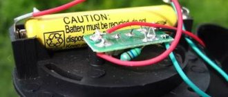
The laurels of primacy go to LED sources and during the recycling process, they can be thrown into the trash. , thrown into a landfill, pollutes the environment (air and groundwater) with toxic mercury vapor, resulting in severe poisoning of people, animals and fish. That is why it must take place in accordance with certain rules.
Despite the pros and cons, LEDs are interchangeable - manufacturers took care of the appropriate size of any of the lamps and sockets for them.
Popular articles DIY solar collector.
What the two competing analogues have in common is a fairly high-quality color flow, providing a high level of comfort for the retina of the human eye.
How to connect a fluorescent lamp to the network - options and diagrams
The popularity of fluorescent lamps is due to several factors. The most important of them are their cost-effectiveness, operating efficiency, as well as uniform light emitted from a sufficiently large surface area. But in addition to these qualities, you need to know the rules for connecting fluorescent lamps. For this, several types of circuits and additional devices are used.
Features of the functioning of luminescent devices
The operation of these light sources is based on the effect of the formation of IR radiation by mercury vapor under the influence of an electric discharge. In practice, to do this, a spiral cathode-anode pair is placed in a glass flask, and the inner surface of the lamp is treated with a phosphor solution. Then the structure is filled with a complex mixture, the main component of which is mercury vapor.
When an electric current is applied, a discharge occurs, which causes the lamp to glow. But unlike similar incandescent models, the discharge value must be clearly standardized. Only if this condition is met is a uniform process of light formation possible.
To accomplish this, two types of devices are used:
- EMPA – ballast. It is better known as a choke. Can be used in conjunction with a starter.
- electronic ballast. A more reliable and technologically advanced way to control the operation of a fluorescent lamp. Its use almost completely eliminates the characteristic blinking of the lamp.
Currently, schemes with the installation of electronic ballasts have become more widespread. This is due to their low cost and the ability to connect several lamps.
Specifics of application of electronic ballasts
To use electromagnetic starting, you will need a compensation capacitor, a choke and a starter. In order to ensure reliable operation of the circuit, all internal wiring must be made with PUGV wires.
Circuit for one lamp
For a better understanding, it is necessary to consider all stages of inclusion:
- After contact K is closed, electric current is supplied to the starter. It is a small gas discharge lamp. At the same time, a glow discharge begins to form in it, the voltage value of which is less than in the network, but more than normalized for the main lighting device.
- Then thermal expansion of the electrodes occurs, as a result of which they are connected, forming an electrical circuit. The amount of current flowing through it directly depends on the parameters of the inductor. It should exceed the number number for the lamp by 1.5-2 times.
- At this time, the cathode-anode pair is preheated in the lamp to form a discharge in a gaseous environment. After opening the inductor electrodes, a high self-induction current appears. The capacitor reduces this value to the desired level.
- A sharp increase in voltage provokes the appearance in the flask of a large number of charged particles, which lead to the formation of plasma and, as a consequence, a gas discharge.
Using the same principle, you can connect two fluorescent lamps. The processes occurring in this chain are almost completely similar to those described above.
Connecting two lights
The disadvantages of this connection method include the short service life of chokes and starters. This is due to the specifics of the processes that occur in them.
Connection using electronic ballasts
It is much more effective to use electronic ballasts - electronic ballasts. Its operating principle differs from EmPRA. This device supplies high-frequency voltage to the lamp contacts, the value of which can vary from 25 to 130 Hz.
To connect the device correctly, just read the instructions first. In most cases, the connection diagram consists of the following steps.
- Connecting contacts to the electrical network.
- Connecting wires to filament terminals. Each of them will require two contacts.
The advantages of using this starting device include significant energy savings, increased service life, as well as a complete absence of flicker and noise typical of fluorescent lighting devices.
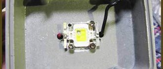
LED design
LED lamp design
An LED tube is a transparent plastic bulb, inside of which there is a driver and a getinax strip with LEDs mounted on it. For this reason, installing an external driver is not necessary. This lamp is connected to a standard 220 V network.
The LED daylight is equipped with a G13 socket. The lamp pins are connected to each other inside the bulb using copper wire, so that voltage can be applied to any of the pins.
LED tubes are manufactured in lengths of 600 or 1500 mm. Their power varies between 9-25 W. The emitted light can be either warm or cold. LEDs are 60-65% more economical than fluorescent lamps.
LEDs can have a wide variety of shapes. The most common design is the classic 5mm case. The top is equipped with a lens, and the bottom is equipped with a reflector. Inside the case there is a crystal that emits light when current passes through it.
The design of the LED is trivial: it has two outputs - anode and cathode. A parabolic aluminum reflector (reflector) is located on the cathode. Outwardly, it is similar to a cup-shaped depression.
The key component of the LED is a semiconductor single crystal in which the pn junction occurs. The single crystal itself has the shape of a cube with dimensions of 0.3x0.3x0.25 mm.
The crystal is connected to the anode via a gold-plated jumper wire. The body is made of polymer, it is optically transparent and simultaneously serves as a focusing lens. Together with the reflector, they set the angle of radiation of the LED and the direction of the light flux.
Typical ballast circuit
The electronic ballast design uses an active power factor correction, ensuring compatibility with the electrical network. The basis of the corrector is a powerful boost pulse converter controlled by a special integrated circuit. This provides rated operation with a power factor close to 0.98. The high value of this coefficient is maintained in any operating mode. Voltage changes are allowed in the range of 220 volts + 15%. The corrector ensures stable illumination even with significant changes in network voltage. To stabilize it, an intermediate DC circuit is used.
An important role is played by the mains filter, which smoothes out high-frequency ripples of the supply current. Together with the corrector, this device strictly regulates all components of the consumed current. The line filter input is equipped with a protective unit with a varistor and a fuse. This allows you to effectively eliminate network overvoltages. A thermistor having a negative temperature coefficient of resistance is connected in series with the fuse, which ensures that the input current surge is limited when the electronic ballast is connected from the inverter to the network.
In addition to the main elements, the ballast circuit for fluorescent lamps requires the presence of a special protection unit. With its help, the status of the lamps is monitored, as well as their shutdown in case of malfunction or absence. This device monitors the current consumed by the inverter and the voltage supplied to each lamp. If during a certain period of time the specified voltage or current level exceeds the set value, then the protection is triggered. The same thing happens during a load circuit break.
The executive element of the protective unit is a thyristor. Its open state is maintained by current passing through a resistor installed in the ballast. The value of the ballast resistance allows the thyristor current to maintain the on state until the supply voltage is removed from the electronic ballast.
The electronic ballast control unit is powered through a mains rectifier when current passes through the ballast resistor. Reducing the power of the electronic ballast and improving its efficiency allows the use of smoothing circuit current. This circuit connects to the point where the inverter transistors connect. Thus, the control system is powered. The construction of the circuit ensures that the control system is launched at the initial stage, after which the power circuit is started with a slight delay.
Electronic ballast device
As can be seen from the circuit diagram, the starter in the form of an electronic ballast is a kind of voltage converter. A miniature inverter converts direct current into high frequency alternating current. This current is supplied to the heating electrodes. The heating intensity of these electrodes increases. The converter is turned on in such a way that in the first stages the current frequency is high. The fluorescent lamp itself is included in a circuit whose resonant frequency is lower than the initial frequency of the converter. Subsequently, the frequency decreases, and the voltage, and the voltage on the oscillating circuit and on the lamp increases, as a result of which the circuit begins to approach resonance. At the same time, the degree of heating of the electrodes increases. This leads to the creation of conditions for the occurrence of a discharge in the gas mixture and the phosphor coating of the flask begins to glow.
The electronic ballast is designed in such a way that the control device can adapt to the characteristics of the fluorescent lamp. This makes it possible to maintain the original light characteristics of the lighting device for a long time. As fluorescent lamps wear out, they require more and more voltage to reach the initial discharge point. The electronic ballast independently adapts to the changes that have occurred and the quality of lighting remains the same.
Compared to throttle ballast, electronic ballast has several advantages:
- it provides greater efficiency during operation;
- makes it possible to create conditions for gentle heating of the electrodes;
- ensures smooth switching on of the lamp;
- the use of electronic balance makes it possible to overcome such a disadvantage of fluorescent lighting as flickering;
- makes it possible to use fluorescent lamps in cold conditions;
- increases temporary performance characteristics;
- has much less weight and dimensions.
The disadvantages of electronic ballast include high requirements for the quality of components, as well as the accuracy of installation, and the complexity of the connection diagram.
Aquarium lighting time
Light should not be supplied to the aquarium around the clock - this is unnatural for plants and pets. Fish and aquarium plants are inhabitants of the tropics and subtropics. There daylight hours, regardless of the time of year, last about 12 hours. This is the time when the backlight should work. It’s even better if the owners have the opportunity to increase the brightness of the lighting for several hours during the day, creating a kind of half-day. To do this, install several lamps at once, which will turn on separately. To automate the process, mechanical or electronic relays are used. The last option is the most convenient, as it makes it possible to program the time for turning the lamps on and off.
Proper lighting of a closed ecosystem is a very important factor for the normal growth and development of plants and pets. Light affects photosynthesis, oxygen saturation of water, without which the vital activity of living organisms is impossible. A competent approach to organizing lighting and accurate calculations will allow you to independently make inexpensive but effective lighting for an aquarium, which can be used both as functional and decorative.
How is the lighting arranged in your aquarium? Share your experience in the comments.
Circuits with starter
The very first circuits with starters and chokes appeared. These were (in some versions they are) two separate devices, each of which had its own socket. There are also two capacitors in the circuit: one is connected in parallel (to stabilize the voltage), the second is located in the starter housing (increases the duration of the starting pulse). This whole “economy” is called electromagnetic ballast. The diagram of a fluorescent lamp with a starter and choke is shown in the photo below.
Connection diagram for fluorescent lamps with starter
Here's how it works:
- When the power is turned on, current flows through the inductor and enters the first tungsten coil. Next, through the starter it enters the second spiral and leaves through the neutral conductor. At the same time, the tungsten filaments gradually heat up, as do the starter contacts.
- The starter consists of two contacts. One is fixed, the second is movable bimetallic. In normal condition they are open. When current passes, the bimetallic contact heats up, which causes it to bend. By bending, it connects to a fixed contact.
- As soon as the contacts are connected, the current in the circuit instantly increases (2-3 times). It is limited only by the throttle.
- Due to the sharp jump, the electrodes heat up very quickly.
- The starter bimetallic plate cools down and breaks contact.
- At the moment the contact breaks, a sharp voltage surge occurs across the inductor (self-induction). This voltage is enough for electrons to break through the argon medium. Ignition occurs and the lamp gradually enters operating mode. It occurs after all the mercury has evaporated.
The operating voltage in the lamp is lower than the mains voltage for which the starter is designed. That's why it doesn't work after ignition. When the lamp is working, its contacts are open and it does not participate in its operation in any way.
This circuit is also called electromagnetic ballast (EMB), and the operating diagram of an electromagnetic ballast is called EMBRA. This device is often simply called a choke.
One of the EmPRA
There are quite a few disadvantages to this fluorescent lamp connection scheme:
- pulsating light, which negatively affects the eyes and they quickly get tired;
- noise during start-up and operation;
- inability to start at low temperatures;
- long start - about 1-3 seconds pass from the moment of switching on.
Two tubes and two chokes
In luminaires with two fluorescent lamps, two sets are connected in series:
- the phase wire is supplied to the inductor input;
- from the throttle output it goes to one contact of lamp 1, from the second contact it goes to starter 1;
- from starter 1 it goes to the second pair of contacts of the same lamp 1, and the free contact is connected to the neutral power wire (N);
The second tube is also connected: first the choke, from it to one contact of lamp 2, the second contact of the same group goes to the second starter, the starter output is connected to the second pair of contacts of the lighting device 2 and the free contact is connected to the neutral input wire.
Connection diagram for two fluorescent lamps
The same connection diagram for a two-lamp fluorescent lamp is demonstrated in the video. This might make it easier to deal with the wires.
https://youtube.com/watch?v=8fF5KQk4L2k
Connection diagram for two lamps from one choke (with two starters)
Almost the most expensive in this scheme are the chokes. You can save money and make a two-lamp lamp with one choke. How - watch the video.
Making lampshades on a frame
There are enough options for how to make a lampshade cover:
From tapes
The easiest and fastest way to transform an old lampshade for a floor lamp or table lamp is to use ribbons. You need a frame or lampshade in the form of a cylinder. It can be “naked” or covered with fabric. If you use a “bare” frame, light will shine through the cracks, which will create interesting lighting effects, but the lighting will be uneven. It is uncomfortable to read in this light - this is an interior solution. If you need even lighting, first cover the frame with fabric. It can be the same color as the ribbons, a couple of shades darker or lighter, or it can be contrasting. It all depends on your desire. And remember that the darker the fabric, the less light the lampshade lets in.
We take a ribbon 1-2.5 cm wide. We fix it on the wrong side of the lampshade using PVA glue, additionally securing it with a pin. If you took a wire frame without fabric, attach it to the upper or lower rim (you can sew it on by hand, you can use glue). Then we begin to wrap the entire frame, from top to bottom, placing the turns of tape close to each other, but without overlapping.
Having completed the circle, turn the tape 90°. We fix it in this position (with a needle and thread or PVA glue, glue from a gun, temporarily fixing it with a pin, pressing it with a clothespin). Then we pass the tape under the first tape, pull it out, lay it on top of the second, then pull it down again, pull it up through one tape. So, gradually, we create an interlacing, filling the entire lampshade.
Alternatively, you can pass two vertical ribbons at a time. But then you need to make sure that each next row moves one crossbar. Then you get a different type of weave. This type of lampshade is ideal for floor lamps, since the light will be directed downwards and the dispersion through the walls will be small.
In this version, the ribbons can be the same, they can be the same color but of different textures, they can differ by a couple of tones or be contrasting. The tapes can be passed in a circle in a continuous stream, or at some distance. If you find a wide tape and apply it with an overlap, then you won’t need horizontal ones at all. And if you use a braided or twisted cord (in the lower photo on the right), we will get a completely different-looking lampshade. So this lampshade finishing technique alone gives you a lot of options.
Let's briefly present the ideas. There are many options for how you can design standard frames for lampshades in a non-standard way. The first method has already been announced: you can knit or crochet a cover for a lampshade. Several options in the photo.
Not everyone knows how to knit. It is easier to work with beads, especially if you glue them. You can decorate old fabric using beads, sequins, beads of different shapes and sizes. You can make this “new-old” lampshade with your own hands in a couple of hours. Select decorations that match the color, coat the fabric with PVA glue, and stick on the decorations. To complete the look, you can assemble pendants from beads and beads that are attached to the lower rim, but this is already painstaking work. The effect is interesting though.
You can sew a new lampshade from fabric. But it doesn’t have to be an updated copy of the old one. You should use your imagination! If a lamp or floor lamp is in the girls' room, a new cover for the lampshade can be made in the form of a skirt. You choose the style of the skirt yourself. They look interesting when folded. With and without ruffles.
You can use an old geographical map in the boy's room. They are on thick paper. If the paper is not thick enough, you first need to glue the card onto the cardboard, and then glue the lampshade from such a blank.
Original lampshades are obtained if the finished frame is woven with threads or ropes. Ropes can be natural. In this case they are gray, brown and beige. You can find thin synthetic colored cords. They will make products that are more “cheerful” in color. The situation is even simpler with knitting threads. They are thin, thick, textured, with smoothly changing colors. In general, there are a lot of options.
We take the frame and braid it according to a certain pattern. You can start with the racks. Braid each stand with a braid (the length of the threads should be 3 times the height of the stand). When this work is completed, we begin to stretch the threads/ropes between the posts. They will need to be passed through the braids, so with threads it is more convenient to do this with a needle, but ropes can be inserted this way.
The second option is to first entangle the entire frame horizontally, and then braid the racks. The braid won't work here, you just need to secure the turns to the stand using inclined stitches with a certain slope. This option is somewhat simpler in execution, but the “braids” look more decorative.
Electronic ballast
Electronic starting and maintaining the combustion of fluorescent lamps was developed back in the eighties and began to be used in the early nineties of the twentieth century. The use of electronic ballast has made fluorescent lighting 20% more economical.
At the same time, all characteristics of the luminous flux were preserved and improved. Uniform, flickering-free lighting is stable even with network voltage fluctuations.
This was achieved thanks to the increased frequency of the current supplied to the lamps and the high efficiency of electronic devices.
Smooth start-up and soft operating mode made it possible to almost double the service life of the lamps. Additionally, it became possible to smoothly control the brightness of the lamp. The need to use starters has disappeared. Radio interference disappeared with them.
The operating principle of electronic ballast differs from electromagnetic ballast. At the same time, it performs the same functions: heating the gas, igniting and maintaining combustion. But, it makes it more accurate and softer. Various circuits use semiconductors, capacitors, resistors and a transformer.
Electronic ballasts can have different circuit designs depending on the components used. Simplified, the passage of current through the circuit can be described by the following algorithm:
- Voltage is supplied to the rectifier.
- The rectified current is processed by an electronic converter, using a microcircuit or self-oscillator.
- Next, the voltage is regulated by thyristor switches.
- Subsequently, one channel is filtered by a choke, the other by a capacitor.
- And through two wires the voltage is supplied to a pair of lamp contacts.
- The other pair of lamp contacts is closed through a capacitor.
An advantageous difference between electronic systems is that the voltage supplied to the contacts of the lamps has a higher frequency than that of electromagnetic ones. It varies from 25 to 140 kHz. That is why in electronic ballast systems the flickering of lamps is minimized and their light is less tiring for the human eye.
Most manufacturers indicate connection diagrams for lamps to electronic ballasts and their power on the top side of the device. Therefore, consumers have a clear example of how to properly assemble and connect the device to the network.
Electronic ballasts provide a different number of connected lamps of different power, for example:
- Philips HF-P series chokes can connect from 1 to 4 tubes with a power of 14 to 40 W.
- Helvar EL series chokes are designed for one to four lamps with a power from 14 to 58 W.
- QUICKTRONIC brand Osram type QTP5 also have the ability to control one to four lamps with a power of 14 - 58 W.
Electronic devices have a lot of advantages, of which the following can be highlighted:
- light weight and small size of the device;
- fast and fluorescent lamp-saving, smooth switching on;
- there is no flicker of light visible to the eye;
- high power factor, approximately 0.95;
- the device does not heat up;
- energy savings of 20%;
- high level of fire safety and absence of risks during work;
- long service life of luminescent lamps;
- no high requirements for ambient temperature;
- ability to automatically adjust to flask parameters;
- absence of noise during operation;
- Possibility of smooth adjustment of the light flux.
Noted by many, the only disadvantage of electronic systems is their price. But it is justified by its merits.
How to position aquarium lighting
An aquarium is an interior design element that should fit organically into the overall style of the room. Lighting plays a big role here. It is incorrect to place lamps behind the back wall of the tank, as inexperienced users do. The lamp can be located in front of the aquarium, on top, on the lid, on the sides. If the tank does not have a lid, then the lamps are placed above it.
When using colored and white light simultaneously, it is better to place colored lamps in the foreground, and white lamps in the back. Then you will get an extraordinary iridescence effect on fish scales and plant leaves.
Flickering light will be detrimental for fish, which leads them to severe depression. Also, colored lamps cannot be used as functional lighting. But they can be used as decorative lighting in addition to the main lighting.
Number of lamps and their placement
Economy variant diodes have a power of 80-10 lm per watt. For products from well-known brands it is higher - 140 Lm per watt. Therefore, for a 100 liter aquarium, a tape is suitable, the total area of the diodes will be 50 W. You can also use one or two spotlights, the power of which will not exceed 50 W.
For a 100 liter aquarium, a tape with a total diode area of 50 W is suitable
It is worth considering that if the container is densely planted with plants, the power of the LEDs should be slightly increased.
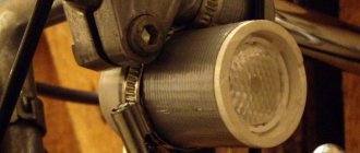
Conversion of a lamp with electronic ballast
If the model of the illuminator is more modern - an electronic ballast choke and no starter - you will have to make an effort and change the connection diagram of the LED tubes. Components of the lamp before replacement:
- throttle;
- wires;
- cartridge pads located on both sides of the body.
We get rid of the throttle first, because... without this element the design will become lighter. Unscrew the fastening and disconnect the power wires. Use a narrow-tipped screwdriver or pliers for this.
The main thing is to connect 220 V to the ends of the tube: apply phase to one end, and zero to the other.
LEDs have a peculiarity - 2 contacts on the base in the form of pins are rigidly connected to each other. And in fluorescent tubes, the contacts are connected by a filament, which, when heated, ignites mercury vapor.
Lighting devices with electronic ballasts do not use a filament, and a voltage pulse breaks through between the contacts.
It is not so easy to supply 220 V between contacts with a hard connection.
To make sure the voltage is correct, use a multimeter. Set the device to resistance measurement mode, touch the two contacts with the measuring probes and take measurements. The multimeter display should show a zero value or close to it.
LED lamps have a filament between the output contacts, which has its own resistance. After applying voltage through it, the filament heats up and causes the lamp to work. Further connection of the LED lamp is recommended to be done using 2 methods:
- without dismantling cartridges;
- with dismantling and installing jumpers between the contacts.
What needs to be redone
If the starter is not removed from the circuit, when replacing the LB lamp with an LED one, a short circuit can be created.
The overall dimensions of LED lamps are similar to the dimensions of fluorescent lamps, so the ceiling lamp itself does not have to be structurally altered. Changes concern only the internal electrical circuit. LED lamps operate directly from the network and do not require ballasts, so this unit must be removed from the lamp.
Rework involves the following actions
- starter removal;
- short circuit and subsequent removal of ballast;
- disconnecting the capacitor.
After completing these steps, you can begin to implement the final luminaire circuit.
Before converting a fluorescent lamp to an LED one, you need to pay attention to the type of base. They are rotatable and rigidly fixed. The most versatile are the rotary type. They can be installed in any converted lighting fixture, regardless of the type of slots in the socket - horizontal/vertical. In addition, rotating bases allow you to change the angle of the light flux.
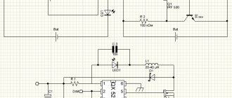
Power supply from 220V without choke and starter
The fact is that starters periodically fail, and chokes burn out. All this is not cheap, so there are several schemes for connecting a lamp without these elements. You can see one of them in the picture below.
You can choose any diodes with a reverse voltage of at least 1000V and a current not less than the lamp consumes (from 0.5 A). Choose capacitors with the same voltage of 1000V and a capacity of 1-2 µF
Please note that in this connection circuit the lamp terminals are closed to each other. This means that the spirals do not participate in the ignition process and the circuit can be used to ignite lamps where they have burned out
This scheme can be used to illuminate utility rooms and corridors. You can use it in the garage if you do not work on machines there. The light output may be lower than with a classic connection, and the light output will flicker, although this is not always noticeable to the human eye. But such lighting can cause a stroboscopic effect - where rotating parts may appear to be stationary. Accordingly, this can lead to accidents.
We recommend: Do-it-yourself single-pipe heating system for a private house
Note: during experiments, keep in mind that starting fluorescent light sources in the cold season is always difficult.
The video below clearly shows how to start a fluorescent lamp using diodes and capacitors:
There is another diagram for connecting a fluorescent lamp without a starter and choke. An incandescent light bulb is used as ballast.
Use an incandescent lamp at 40-60 W, as shown in the photo:
An alternative to the described methods is to use a board from energy-saving lamps. In fact, this is the same electronic ballast that is used with tubular analogues, but in a miniature format.
The video below clearly shows how to connect a fluorescent lamp through an energy-saving lamp board:
2
Connection with electromagnetic ballast - classic scheme
The first fluorescent lamps were switched on via the throttle and starter. Previously, these were separate devices (in some models they still are) with sockets in the lamp body for each. The circuit also has 2 capacitors. One is located in the starter - it prolongs the impulse, the second stabilizes the voltage. All equipment is called electromagnetic ballast.
This type of connection has several advantages:
has passed the test of time and confirmed its reliability; simple; components are inexpensive.
Practical application has revealed many disadvantages, especially in comparison with the electronic circuit for connecting the LDS:
consumes 15%!b (MISSING) more electricity; heavy lighting device; takes a long time to turn on, especially when the lamp gets old; works poorly in the cold; throttle hums, the sound increases over time; light flickers, which is bad for vision. Circuit for one lamp
When installing, first insert the starter into the socket to connect to the filaments in the bulb. A choke is connected to the free contacts. A capacitor is installed in parallel on the network wires.
System health check
After connecting the fluorescent lamp, you should make sure that it is working and that the ballasts are in good working order. To carry out the tests, you will need a tester with which to check the cathode filaments. The permissible resistance level is 10 ohms.
If the tester determines the resistance to be infinite, it is not necessary to throw away the light bulb. This light source still retains functionality, but it must be used in cold start mode. In the normal state, the starter contacts are open, and its capacitor does not allow direct current to pass through. In other words, the ringing should show a very high resistance, which sometimes reaches hundreds of ohms.
After touching the choke terminals with the ohmmeter probes, the resistance gradually decreases to a constant value inherent in the winding (several tens of Ohms).
Note! The faulty state of the throttle is indicated by the burnout of a recently installed light bulb.
It is not possible to reliably determine the turn-to-turn short circuit in the inductor winding using a conventional ohmmeter. However, if the device has an inductance measurement function and data on electronic ballasts, a discrepancy between the values will indicate a problem.